
Abstract
This paper presents an active wheel mouse that can present slippages to the fingertip skin. The active wheel mouse is a mouse device that embeds a wheel actively rotating in any directions, with any speeds and duration times. Here, raised-dots of 4.5 and 10.5 mm intervals were especially introduced to the peripheral surface of the wheel. As a result of a pilot study by psychophysical experiments, it was suggested that, from the viewpoint of the perceived lengths, the active wheel mouse was effective enough to provide the slippage information and that is superior to the flat surface without raised dots, i.e., non-bumpy surface.
You have full access to this open access chapter, Download conference paper PDF
Keywords
1 Introduction
The objective of this study is to develop “an active wheel mouse” that can present slippages to the fingertip skin. The active wheel mouse is a mouse device that embeds a wheel: the wheel actively rotates in any directions, with various speeds and duration times. Here, as a way to enhance the perceptual characteristics, raised-dots were introduced to the peripheral surface of the wheel. Touching on the wheel surface, the users can perceive the slippages of the wheel surface via one’s cutaneous sensation on finger-pad: the instantaneous directed velocities of the slippages can be recognized as the instantaneous directed velocities of the moving surfaces, and, the integrations of the instantaneous directed velocities over some duration time result in the lengths of the slippages. Thus, we can be recognized motion trajectories of the moving surfaces. This function can be utilized for various situations. For example, we can employ one of the so-called “stop and go” schemes as in the following.
-
[“Stop” phase] Computer rotates a wheel in some direction with a speed and for a duration time. Then, we can recognize a directed line segment from the presented slippage.
-
[“Go” phase] Regarding the directed line segment as hand motion, and, actively moving the mouse, we recognize a hand movement, i.e., a stroke, through the motion.
Furthermore, by consecutively iterating the “stop and go” phase, we can learn a series of hand movements. The hand movements could be brush strokes of line drawings such as calligraphies and route maps. This function, as it were, can be regarded as a computer-to-human communication. Needless to say, the active wheel mouse inherits the hand positioning and the clicking function as in ordinary mouse devices. These functions can be regarded as a computer-to-human communication.
Beside the stop and go scheme, we can employ an on-line feedback schemes between computer and user as in the following. If we recognize the perceived slippage velocities presented by wheel as the hand-motion velocities, we are momentarily able to be instructed how to move our hand. By accepting the momentary instructions continuously, we would be able to learn curved hand movements. This hand motion instructing function would be helpful for with visually impaired persons.
Thus, the active wheel mouse is expected to work as a novel interfaces enabling us to communicate by motions with computer in a mutual way. This paper presents a result of a pilot study by a psychophysical experiment on the cutaneous sensory characteristics of the slippages of the wheel surface on a fingertip.
2 Design of Active-Wheel Mouse
2.1 Previous Works
Tsagarakis et al. proposed a slip displaying device made of a pair of cones [1]. The effects of the tangential contact displacement were studied by Salada et al. [2]. For the use of the raised dot for slip speed perception, Dépeault et al. (2008) studied the slip-speed scaling. They dealt with the perception of the slip-speeds not by absolute values, but by relative ones, i.e., the ratios of the test speed against a standard one [3]. As for mouse type fingertip tactile devices, Gleeson et al. proposed a fingertip-mounted tactile display reflecting a tangential skin displacement feedback [4]. Moscatelli et al. proposed a sphere-based slippage presenting device [5].
2.2 Purpose and Solution
The purpose is to develop a mouse which presents displacement vectors, i.e., line segments via cutaneous slippage sensation on the human fingerpad. Aiming at the purpose, as a human-computer information channel, we employ cutaneous slippage sensation on the fingerpad. That is, as shown in Fig. 1, we developed an “active wheel mouse ”: it embeds two stepping motors that rotate the wheel of 20 mm in diameter with respect to the orthogonal two axes, i.e., one rotates the wheel of 20 mm in diameter, and the other changes the direction of rotation (see Fig. 2). Especially, we introduced raised dots on the wheel peripheral surface (see Fig. 3). Practically, in order to clarify the effectiveness of the raised dots, we employed three kinds of wheels: the first and the second wheel have surfaced with the raised dots of intervals, 4.5 and 10.5 mm, and the third wheel has a flat surface without raised dot.

Active wheel mouse

Two stepping motors (M25SP-6NK and M15SP-2 N, MITSUMI ELECTRIC CO., LTD., Tokyo, Japan)

Wheel with raised dots
3 Experiment
3.1 Experimental Conditions
The factors and their corresponding factor levels employed in an experiment were as follows:
-
Control factor to be optimized
-
Surface factor: (3 levels) two kinds of dotted surfaces of intervals, 4.5 and 10.5 mm and a flat surface without dot
-
-
Signal factors being related to presented slippages
-
Length factor: (6 levels) 25, 50, 75, 100, 125, 150 mm.
-
Angle factor: (12 levels) 0, 30, ~ , 300, 330 degrees (30 degree steps)
-
Speed factor: (3 levels) 30, 60, 120 mm/s
-
-
Error factor
-
Subject factor: (2 levels) 2 people aged 22 and 26, right handedness
-
Repetition number: (2 levels) 2 times repeated
-
3.2 Experimental Procedures
As for the conditions described in the former section, we employed an orthogonal array of 72 runs based on the experimental design scheme. For each of the run, subjects were asked to perform the following procedures.
- Step 1::
-
Subjects closed their eyes and touched the wheel surface on their fingerpad through an opening (see Fig. 4)
- Step 2::
-
Subjects perceived the slippage length and angle by using their fingerpad cutaneous sensation
- Step 3::
-
When the wheel stopped, subjects answered their perceived length and angle by touching a start and an end point on a touch panel display (see Fig. 5)
Fig. 4. 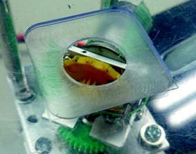
Active wheel viewed from an opening through which users put their fingertip on the wheel peripheral surface.
Fig. 5. 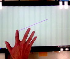
Subjects answered their perceived slippages by using a touch panel display


3.3 Experimental Results
The relative errors, i.e., the ratios of the absolute errors against the true lengths, were examined, and were summarized from the viewpoints of the systematic error, i.e., sample mean of the error, and the standard error of the random error. To evaluate the perceived length quantitatively, a relative error measure, e l , was employed as follows.
where l and L denote the perceived and actual length, respectively.
Before explaining the experimental results, it should be noted that the sample number was too small to make the conclusion statistically legitimate.
Perceived length.
For the three kinds of surfaces, the systematic errors are shown in Fig. 6 together with the standard errors being proportional to the random errors. Length factor effect with perceived length relative errors was also shown in Fig. 7.

Surface factor effect with perceived length relative errors (Error bar: standard error)

Length factor effect with perceived length relative errors (Error bar: standard error)
For the perceived length data, statistical tests were applied to confirm the significances of the factor effects, and the test results are shown in Table 1: the systematic errors were test by ANOVA, and the random errors were by Bartlett’s test.
As for the perceived length relative errors, it seems to be that the raised dots are superior to the flat surface, especially from the viewpoints of the systematic errors from Fig. 6. We can see a lengthening effect in short lengths of presented slippages, and the shortening effect in long lengths of presented slippages from Fig. 7 as in the previous works [6–9].
Perceived direction.
For the three kinds of surfaces, the systematic errors are shown in Fig. 8 together with the standard errors being proportional to the random errors. Direction factor effect with perceived directional errors was also shown in Fig. 9.

Surface factor effect with perceived directional errors (Error bar: standard error)

Direction factor effect with perceived directional errors (Error bar: standard error)
For the perceived direction data, statistical tests were also applied to confirm the significances of the factor effects, and the test results are shown in Table 2.
As for the perceived directional errors, it seems to be that the raised dots didn’t show any significant difference among the three surfaces from the viewpoints both of the systematic and of the random errors. There were only a significant difference with the directional factor effect: the systematic error shows the tendency of perceiving the directions as orthogonal angles as in the previous work [7] (Table 2).
4 Conclusions
An active wheel mouse that can present slippages to the fingertip skin was developed, and a pilot study was conducted by a psychophysical experiment. Here, we, especially, introduced the raised dots of 4.5 and 10.5 mm intervals to the wheel surface together with the flat surface without raised dots for comparison.
As a result of the pilot study, it was suggested that, from the viewpoint of the perceived lengths, the active wheel mouse was effective enough to provide the slippage information and that is superior to the flat surface.
In the future, the sample size should be increased enough, and the results are used for acquiring line drawing information with visually impaired persons.
References
Tsagarakis, N.G., Horne, T., Caldwell, D.G.: Slip aestheasis: a portable 2D slip/skin stretch display for the fingertip. In: Eurohaptics Conference, 2005 and Symposium on Haptic Interfaces for Virtual Environment and Teleoperator Systems, World Haptics 2005, First Joint. IEEE (2005)
Salada, M., et al.: An experiment on tracking surface features with the sensation of slip. In: Eurohaptics Conference, 2005 and Symposium on Haptic Interfaces for Virtual Environment and Teleoperator Systems, World Haptics 2005, First Joint. IEEE (2005)
Dépeault, A., Meftah, E.M., Chapman, C.E.: Tactile speed scaling: contributions of time and space. J. Neurophysiol. 99(3), 1422–1434 (2008)
Gleeson, B.T., Horschel, S.K., Provancher, W.R.: Design of a fingertip-mounted tactile display with tangential skin displacement feedback. IEEE Trans. Haptics 3(4), 297–301 (2010). IEEE
Moscatelli, A., Naceri, A., Ernst, M.: Navigation in the fingertip. In: 2013 World Haptics Conference (WHC). IEEE (2013)
Syed Yusoh, S.M.N., Nomura, Y., Sakamoto, R., Iwabu, K.: A study on the duration and speed sensibility via finger-pad cutaneous sensations. Procedia Eng. 41, 1268–1276 (2012)
Nomura, Y., Syed Yusoh, S.M.N., Sakamoto, R.: Hand-motion perception by four haptic modes: active/passive and with/without fingerpad cutaneous sensation. J. Adv. Mech. Des. Syst. Manufact. 7(4), 560–575 (2013)
Nomura, Y., Iwabu, K.: Length perceptual characteristics on raised-dot slippages. In: Human-Computer Interfaces and Interactivity: Emergent Research and Applications, pp. 286–308. IGI Global (2014)
Nomura, Y., Kato, H.: Raised-dot slippage perception on a fingerpad using an active wheel device. In: Recent Advances on Using Virtual Reality Technologies for Rehabilitation. Nova Science Publishers (2015)
Acknowledgement
This work was supported by KAKENHI (Grant-in-Aid for scientific research (B) 19H02929 from JSPS).
Author information
Authors and Affiliations
Corresponding author
Editor information
Editors and Affiliations
Rights and permissions
Copyright information
© 2016 Springer International Publishing Switzerland
About this paper
Cite this paper
Nomura, Y., Oike, S. (2016). Active-Wheel Mouse for Human-Computer Interface. In: Antona, M., Stephanidis, C. (eds) Universal Access in Human-Computer Interaction. Interaction Techniques and Environments. UAHCI 2016. Lecture Notes in Computer Science(), vol 9738. Springer, Cham. https://doi.org/10.1007/978-3-319-40244-4_6
Download citation
DOI: https://doi.org/10.1007/978-3-319-40244-4_6
Published:
Publisher Name: Springer, Cham
Print ISBN: 978-3-319-40243-7
Online ISBN: 978-3-319-40244-4
eBook Packages: Computer ScienceComputer Science (R0)