
Abstract
In this paper we present efficient quadrature rules for the numerical approximation of integrals of polynomial functions over general polygonal/polyhedral elements that do not require an explicit construction of a sub-tessellation into triangular/tetrahedral elements. The method is based on successive application of Stokes’ theorem; thereby, the underlying integral may be evaluated using only the values of the integrand and its derivatives at the vertices of the polytopic domain, and hence leads to an exact cubature rule whose quadrature points are the vertices of the polytope. We demonstrate the capabilities of the proposed approach by efficiently computing the stiffness and mass matrices arising from hp-version symmetric interior penalty discontinuous Galerkin discretizations of second-order elliptic partial differential equations.
1 Introduction
In recent years the exploitation of computational meshes composed of polygonal and polyhedral elements has become very popular in the field of numerical methods for partial differential equations. Indeed, the flexibility offered by polygonal/polyhedral elements allows for the design of efficient computational grids when the underlying problem is characterized by a strong complexity of the physical domain, such as, for example, in geophysical applications, fluid-structure interaction, or crack propagation problems. Moreover, the possibility to adopt computational meshes with hanging nodes is included in this framework by observing that, for example, a classical quadrilateral element with a hanging node on one of its edges can be treated as a pentagon with two aligned edges. Several conforming numerical discretization methods which admit polygonal/polyhedral meshes have been proposed within the current literature; here, we mention, for example, the Composite Finite Element Method [5, 41, 42], the Mimetic Finite Difference (MFD) method [4, 18,19,20,21, 44], the Polygonal Finite Element Method [63], the Extended Finite Element Method [37, 64], the Virtual Element Method (VEM) [10, 11, 15,16,17] and the Hybrid High-Order (HHO) method [33,34,35]. In the non-conforming setting, we mention Discontinuous Galerkin (DG) methods [1,2,3, 6, 9, 14, 22,23,24,25, 25], Hybridizable DG methods [29,30,31,32], non-conforming VEM [8, 13, 26], and the Gradient Schemes [36]; here the possibility of defining local polynomial discrete spaces follows naturally with the flexibility provided by polytopic meshes.
One of the key aspects concerning the development of efficient finite element discretizations with polygonal/polyhedral grids is the construction of quadrature formulae for the approximate computation of the terms appearing in the underlying weak formulation. Indeed, the design of efficient quadrature rules for the numerical computation of integrals over general shaped polytopes is far from being a trivial task. The classical and most widely employed technique for the integration over polytopes is the Sub-Tessellation method, cf. [38, 51, 62]; here, the domain of integration is subdivided into standard-shaped elements, such as triangular/quadrilateral elements in 2D or tetrahedral/hexahedral elements in 3D, whereby standard efficient quadrature rules are employed, cf. [50, 60, 70], and also [71] and [48], for an interpolation technique based on the same idea. On the one hand this technique is easy to implement, however, it is generally computationally expensive, particularly for high order polynomials, since the number of function evaluations may be very large.
For this reason, the development of quadrature rules that avoid sub-tessellation is an active research field. Several approaches have been proposed; in particular, we mention [43, 54, 67, 68], for example. One interesting method in this direction is represented by the Moment Fitting Equation technique, firstly proposed by Lyness and Monegato in [49], for the construction of quadrature rules on polygons featuring the same symmetry as the regular hexagon. Generalizations to convex and non-convex polygons and polyhedra were proposed by Mousavi et al. in [53]. Here, starting from an initial quadrature rule, given, for example, by the sub-tessellation method described above, an iterative node elimination algorithm is performed based on employing the least-squares Newton method [69] in order to minimise the number of quadrature points while retaining exact integration. Further improvements of the moment fitting equation algorithm can also be found in [52] and [61]. While this method is optimal with respect to the number of function evaluations, the nodes and weights must be stored for every polygon, thus affecting memory efficiency. An alternative approach designed to overcome the limitations of the sub-tessellation approach is based on employing the generalized version of Stokes’ theorem; here, the exploitation of Stokes’ theorem reduces the integral over a polytope to an integration over its boundary; see [66] for details. For the two-dimensional case, in [59], Sommariva and Vianello proposed a quadrature rule based on employing Green’s theorem. In particular, if an x- or y-primitive of the integrand is available (as for bivariate polynomial functions), the integral over the polygon is reduced to a sum of line integrations over its edges. When the primitive is not known, this method does not directly require a sub-tessellation of the polygon, but a careful choice of the parameters in the proposed formula leads to a cubature rule that can be viewed as a particular sub-tessellation of the polygon itself. However, it is not possible to guarantee that all of the quadrature points lie inside the domain of integration. An alternative and very efficient formula has been proposed by Lasserre in [47] for the integration of homogeneous functions over convex polytopes. This technique has been recently extended to general convex and non-convex polytopes in [27]. The essential idea here is to exploit the generalized Stokes’ theorem together with Euler’s homogeneous function theorem, cf. [58], in order to reduce the integration over a polytope only to boundary evaluations. The main difference with respect to the work presented in [59] is the possibility to apply the same idea recursively, leading to a quadrature formula which exactly evaluates integrals over a polygon/polyhedron by employing only point-evaluations of the integrand and its derivatives at the vertices of the polytope.
In this article we extend the approach of [27] to the efficient computation of the volume/face integral terms appearing in the discrete weak formulation of second-order elliptic problems, discretized by means of high-order DG methods. We point out that our approach is completely general and can be directly applied to other discretization schemes, such as VEM, HHO, Hybridisable DG, and MFD, for example. We focus on the DG approach presented in [25], where the local polynomial discrete spaces are defined based on employing the bounded box technique [39]. We show that our integration approach leads to a considerable improvement in the performance compared to classical quadrature algorithms based on sub-tessellation, in both two- and three-dimensions. The outline of this article is as follows: in Sect. 2 we recall the work introduced in [27], and outline how this approach can be utilized to efficiently compute the integral of d-variate polynomial functions over general polytopes. In Sect. 3 we introduce the interior penalty DG formulation for the numerical approximation of a second-order diffusion–reaction equation on general polytopic meshes. In Sect. 4 we outline the exploitation of the method presented in Sect. 2 for the assembly of the mass and stiffness matrices appearing in the DG formulation. Several two- and three-dimensional numerical results are presented in Sect. 5 in order to show the efficiency of the proposed approach. Finally, in Sect. 6 we summarise the work undertaken in this article and discuss future extensions.
2 Integrating Polynomials over General Polygons/Polyhedra
In this section we review the procedure introduced by Chin et al. in [27] for the integration of homogeneous functions over a polytopic domain. To this end, we consider the numerical computation of \( \int _{{\mathscr {P}}} g({\mathbf {x}}) \mathrm {d} {\mathbf {x}},\) where
-
\({\mathscr {P}} \subset \mathbb {R}^d \textit{, }d=2,3\), is a closed polytope, whose boundary \(\partial {\mathscr {P}} \) is defined by m \((d-1)\)-dimensional faces \({\mathcal {F}}_i,\ i=1,\ldots ,m\). Each face \({\mathcal {F}}_i\) lies in a hyperplane \({\mathcal {H}}_i\) identified by a vector \({\mathbf {a}}_i \in \mathbb {R}^d \) and a scalar number \(b_i\), such that
$$\begin{aligned} {\mathbf {x}} \in {\mathcal {H}}_i \iff {\mathbf {a}}_i \cdot {\mathbf {x}} = b_i, \quad i=1,\ldots ,m. \end{aligned}$$(1)We observe that \({\mathbf {a}}_i\), \(i=1,\ldots ,m\), can be chosen as the unit outward normal vector to \({\mathcal {F}}_i\), \(i=1,\ldots ,m\), respectively, relative to \({\mathscr {P}} \), cf. Figs. 1 and 2.
-
\(g:{\mathscr {P}} \rightarrow \mathbb {R}\) is a homogeneous function of degree \(q \in \mathbb {R}\), i.e., for all \(\lambda > 0\), \(g(\lambda {\mathbf {x}}) = \lambda ^q g({\mathbf {x}})\) for all \({\mathbf {x}} \in {\mathscr {P}} \).
We recall that Euler’s homogeneous function theorem [58] states that, if g is a homogeneous function of degree \(q \ge 0\), then the following identity holds:
Next we introduce the generalized Stokes’ theorem, which can be stated as follows, cf. [66]: given a generic vector field \({\mathbf {X}}: {\mathscr {P}} \rightarrow \mathbb {R}^d \), the following identity holds
where \({\mathbf {n}}\) is the unit outward normal vector to \({\mathscr {P}} \) and \(\mathrm {d} \sigma \) denotes the \((d-1)\)-dimensional (surface) measure. Selecting \({\mathbf {X}} = {\mathbf {x}} \) in (3), and employing (2), gives

Example of a two-dimensional polytope \({\mathscr {P}} \) and its face  . The hyperplane
  is defined by the local origin \({\mathbf {x}} _{0,i}\) and the vector \({\mathbf {e}}_{i1}\)

The dodecahedron \({\mathscr {P}} \) with pentagonal faces and the face  with unit outward normal vector \({\mathbf {n}}_i\). Here,
  has five edges
  , and five unit outward normal vectors \({\mathbf {n}}_{ij},\ j=1,\ldots ,5\), lying on the plane
  . The hyperplane
  is identified by the local origin \({\mathbf {x}} _{0,i}\) and the orthonormal vectors \({\mathbf {e}}_{i1}, {\mathbf {e}}_{i2}\)
Equation (4) states that if g is homogeneous, then the integral of g over a polytope \({\mathscr {P}} \) can be evaluated by computing the integral of the same function over the boundary faces  , \(i=1,\ldots ,m\). By applying Stokes’ theorem recursively, we can further reduce each term
  , to the integration over \(\partial {\mathcal {F}}_i,\ i=1,\ldots ,m\), respectively. To this end, Stokes’ theorem needs to be applied on the hyperplane \({\mathcal {H}}_i,\ i=1,\ldots ,m\), in which each \({\mathcal {F}}_i,\ i=1,\ldots ,m\), lies, respectively. In order to proceed, let \(\varvec{\gamma } : \mathbb {R}^{d-1} \rightarrow \mathbb {R}^d \) be the function which expresses a generic point \(\tilde{{\mathbf {x}}} = (\tilde{x}_1,\ldots ,\tilde{x}_{d-1})^\top \in \mathbb {R}^{d-1}\) as a point in \(\mathbb {R}^d \) that lies on \({\mathcal {H}}_i,\ i=1,\ldots ,m\), i.e.,
Here, \({\mathbf {x}} _{0,i} \in {\mathcal {H}}_i,\ i=1,\ldots ,m\), is an arbitrary point which represents the origin of the coordinate system on \({\mathcal {H}}_i\), and \(\{ {\mathbf {e}}_{in} \}_{n=1}^{d-1}\) is an orthonormal basis on \({\mathcal {H}}_i,\ i=1,\ldots ,m\); see Figs. 1 and 2 for two- and three-dimensional examples, respectively. Notice that \({\mathbf {x}} _{0,i}\) does not have to lie inside  . Let
. Let  such that
  , then the following identity holds:

Before outlining the details regarding the recursive application of the Stokes’ Theorem to (4), we first require the following lemma.
Lemma 1
Let  be the vertices/edges of
  for \(d=2,3\), respectively, and let \({\mathbf {n}}_{ij}\) be the unit outward normal vectors to
  lying in
  . Moreover, let
  be the preimage of
  with respect to the map \(\varvec{\gamma }\), and \(\widetilde{{\mathbf {n}}}_{ij}\) be the corresponding unit outward normal vector. Then, the following holds
where \(\underline{{\mathbf {E}}} \in \mathbb {R}^{d \times (d-1)}\), whose columns are the vectors \(\{ {\mathbf {e}}_{in} \}_{n=1}^{d-1},\ i=1,\ldots ,m\).
Proof
We first note that employing the definition of \(\varvec{\gamma }\) we have that
The proof now follows immediately from simple linear algebra considerations; for full details, we refer to [7]. \(\square \)
Given identity (5) and Lemma 1, we can prove the following result.
Proposition 1
Let  be a face of the polytope \({\mathscr {P}} \), and let
  , \(j=1,\ldots ,m_i\), be the planar/straight faces/edges such that
  for some \(m_i \in \mathbb {N}\). Then, for any homogeneous function g, of degree \(q \ge 0\), the following identity holds

where \(d_{ij}\) denotes the Euclidean distance between  and \({\mathbf {x}} _{0,i}\),
  , is arbitrary, \(i=1,\ldots ,m\), and \(\mathrm {d} \nu \) denotes the \((d-2)\)-dimensional (surface) measure.
Proof
If we denote by \(\nabla _i = \bigl [\frac{\partial }{\partial \tilde{x} _1}, \ldots , \frac{\partial }{\partial \tilde{x} _{d-1}} \bigr ]^\top \) the gradient operator on the hyperplane \({\widetilde{\mathcal {H}}_i},\ i=1,\ldots ,m,\) with respect to the coordinate system \((\tilde{x} _1,\ldots ,\tilde{x} _{d-1})\), then, upon application of Stokes’ theorem, we have

where \(\tilde{{\mathbf {n}}}\) is the unit outward normal vector of \(\widetilde{{\mathcal {F}}_i}\) and \(\widetilde{{\mathbf {X}}}\) is a vector field on \(\mathbb {R}^{d-1}\). Next, we transform (7) back to the original coordinate system. To this end, denoting \(\underline{{\mathbf {E}}} \in \mathbb {R}^{d \times (d-1)}\) to be the matrix whose columns are the vectors \(\{ {\mathbf {e}}_{in} \}_{n=1}^{d-1}\), we observe that, if we choose \(\widetilde{{\mathbf {X}}} = \tilde{{\mathbf {x}}} \), then its divergence is \(\nabla _i \cdot \widetilde{{\mathbf {X}}} = d-1\). Exploiting (6), the term \(\nabla _i g(\varvec{\gamma }(\tilde{{\mathbf {x}}}))\) can be written as follows:
Exploiting (6) and (8), we can write  and
and  as
as


respectively. Employing Lemma 1, together with (6), we have that

We observe that the term \(({\mathbf {x}}- {\mathbf {x}} _{0,i}) \cdot {\mathbf {n}}_{ij} \) is constant for any  , and that it represents the Euclidean distance between
  and \({\mathbf {x}} _{0,i}\); thereby, we define \(d_{ij} = ({\mathbf {x}}- {\mathbf {x}} _{0,i}) \cdot {\mathbf {n}}_{ij}\). From the above identities (9), (10) and (11) we deduce the statement of the Proposition. \(\square \)
Using Proposition 1, together with Eq. (4), we obtain the following identity

where we recall that  and
and  , for \(i=1,\ldots ,m\).
Remark 1
If \(d=2\), then  is a point and (12) states that the integral of g on \({\mathscr {P}} \) can be computed by vertex-evaluations of the integrand plus a line integration of the partial derivative of g. If \(d=3\) we can apply Stokes’ Theorem recursively to
  . Proceeding as before, we get

where  , \({\mathbf {x}} _{0,ij}\) is an arbitrarily chosen origin for
  , and \(d_{ijk}\) is the Euclidean distance between
  and \({\mathbf {x}} _{0,ij}\).
 considered in Algorithm 1 as a function of the dimension d

In view of the application of Proposition 1 to finite element methods, we are interested in the integration of a particular class of homogeneous functions, namely polynomial homogeneous functions of the form
In this case, g is a homogeneous function of degree \(q=k_1 +\cdots + k_d\), and the general partial derivative \(\frac{\partial g}{\partial x_n}\) is a homogeneous function of degree \(q-1\). With this in mind, it is possible to recursively apply formula (12) to the terms involving the integration of the derivatives of g. To this end, we write  , be a N-polytopic domain of integration, with \(N=1,\ldots ,d\), and let
  , where each
  is a \((N-1)\)-polytopic domain. When \(N=d\) and \(d=2,3\),
  will be an edge or a face, respectively; see Table 1 for details. We define the function

which returns the integral of the polynomial \(x_1^{k_1}\ldots x_d^{k_d}\) over  , where \(\mathrm {d} \sigma _N\) is the N-dimensional (surface) measure, \(N=1,2,\ldots ,d\). According to Proposition 1, the recursive definition of the function
  is given in Algorithm 1.
Remark 2
With a slight abuse of notation, when \(1 \le N \le d-1\), in Algorithm 1 (and for the purposes of the following discussion), the point \({\mathbf {x}} _{0} = (x_{0,1},\ldots ,x_{0,d})^\top \) denotes an arbitrarily chosen origin for the coordinate system which defines the N-polytope  and \(d_i\) represents the Euclidean distance between the \((N-1)\)-polytopes
  , which form the boundary of
  , and \({\mathbf {x}} _{0},\ i=1,\ldots ,m\). Furthermore, in Algorithm 1, \(b_i,\ i=1,\ldots ,m,\) is the same constant appearing in (1). Here it can be evaluated as \(b_i = {\mathbf {n}}_i \cdot {\mathbf {v}},\) where \({\mathbf {v}}\) is a vertex of
  and \({\mathbf {n}}_i\) is the unit outward normal vector, \(i=1,\ldots ,m\).
Remark 3
We point out that in (12), cf. also (13), the shape of the underlying polytope can be general: indeed, nonconvex simply-connected domains  are admissable.

Triangle \(({\mathscr {P}} _1)\)

Irregular polygon with 5 faces \(({\mathscr {P}} _2)\)

Irregular polygon with 15 faces \(({\mathscr {P}} _3)\)
2.1 Integration of Bivariate Polynomials over Polygonal Domains
In order to test the performance of the method proposed in Algorithm 1, we consider the integration of bivariate homogeneous functions on a given polygon \({\mathscr {P}} \subset \mathbb {R}^2\) based on using the three different approaches:
- A.1 :
-
Recursive algorithm described in Sect. 2, based on the formula (13):
 cf. Algorithm 1.
 - A.2 :
-
Use of the formula (4) together with numerical integration employed for the evaluation of the edge integrals with known one-dimensional Gaussian quadrature rules, as recently proposed in [28];
- A.3 :
-
Sub-tessellation technique: the domain of integration \({\mathscr {P}} \) is firstly decomposed into triangles where standard efficient quadrature rules are then employed.
 cf. Algorithm 1.
We test the three different approaches for integrating bivariate polynomials of different polynomial degrees on the triangle depicted in Fig. 3 and the two irregular polygons shown in Figs. 4 and 5, cf. Table 2 for the list of coordinates for each domain; the actual values of the integrals are given in Table 3. In Table 4 we show the average CPU-time taken to evaluate the underlying integral using each method. We point out that, for each integrand and each integration domain \({\mathscr {P}} \), the relative errors between the output of the three different approaches are of the order of machine precision; that is, all three algorithms return the exact integral up to roundoff error. For completeness, we note that the times for A.1 include the computation of \(b_i,\ {\mathbf {n}}_i\), and \(d_{ij}\), \(j=1,\ldots ,m_i\), \(i=1,\ldots ,m\). For A.2 we take into account the evaluation of \(b_i,\ {\mathbf {n}}_i\), \(i=1,\ldots ,m\), and the one-time computation of the one-dimensional quadrature defined on \((-1,1)\), consisting of  nodes and weights, employed for the line integrations. Here, we select
  , in order to guarantee the exact integration of \(x^k y^l\). The times for A.3 include the one-time computation of the
  nodes and weights on the reference triangle, where
  is selected as in A.2, the time required for sub-tessellation, as well as the time needed for numerical integration on each sub-triangle. The results shown in Table 4 illustrate that the sub-tessellation approach A.3 is the slowest while the proposed method A.1 is the fastest for all of the considered cases; in particular, we highlight that, even for just a single domain of integration, the former method is between one- to two-orders of magnitude slower than the latter approach proposed in this article. Moreover, when the integration domain consists of a triangle, our algorithm A.1 still outperforms classical quadrature rules, cf. A.3, even though in this case no sub-tessellation is undertaken. When comparing A.1 and A.2, we observe that the former algorithm is again superior in terms of CPU time in comparison with the latter approach; this difference seems to grow when the exponents k and l of the integrand function \(x^ky^l\) are very different. This is because in A.1 we have made an optimal selection of the points \({\mathbf {x}} _{0,i} = (x_{0i,1},x_{0i,2})^\top \), \(i=1,\ldots ,m\), appearing in (12). Indeed, performing the geometric reduction of the edges of the domain of integration, we then choose \(x_{0i,1} = 0\) or \(x_{0i,2}=0\), \(i=1,\ldots ,m\), if the exponents of the integrand function \(x^ky^l\) are \(k \ge l\) or \(k<l\), respectively. The choice \(x_{0i,1} = 0\) or \(x_{0i,2}=0\), \(i=1,\ldots ,m\), allows us to avoid the recursive calls to the function
  related to the x- or y-partial derivatives, respectively. In this way the approach A.1 is able to exploit the form of the integrand in order to optimize the evaluation of the corresponding integral. To explore this issue further, in the following section we consider the computational complexity of A.1 in both the cases when an optimal and non-optimal selection of the points \({\mathbf {x}} _{0,i}\), \(i=1,\ldots ,m\), is made.
2.2 Computational Complexity of Algorithm 1
The computational complexity of Algorithm 1, which is employed in A.1, depends in general on the number of recursive calls of the function  . In particular, using the short-hand notation introduced in Remark 2, the selection of the points \({\mathbf {x}} _{0} = (x_{0,1},\ldots ,x_{0,d})^\top \), which are used to define the origin of the coordinate system of each N-polytope
  which defines the facets of \({\mathscr {P}} \) is crucial. In general, any \((d-1)\)-dimensional hyperplane in \(\mathbb {R}^d\) possesses a non-empty intersection with some axis of the Cartesian reference system, which means that it is always possible to choose \((d-1)\) components of \({\mathbf {x}} _{0}\) as zero. Without loss of generality we select \(x_{0,r} = \nicefrac {b_i}{n_{i,r}}\) and \(x_{0,s} = 0\) for \(s \ne r\), where \(b_i\) and \({\mathbf {n}}_i\) are as defined in Remark 2, and \(r \in \{ 1,\ldots ,d\}\) is chosen so that \( k_r = \min \{ k_1,\ldots ,k_d\}.\)
Remark 4
In general, if  is a N-polytopic domain in \(\mathbb {R}^d\), then at most N components of
  can be selected to be zero.
In this way, the selection of \(k_r\) essentially fixes the number of recursive calls of  in Algorithm 1. More precisley, we write
  to denote the number of FLOPs to perform
  , and let \(C_N\) be the number of FLOPs required by
  , without considering the recursive calls of
  to itself. With this in mind, let us consider the following two examples:
-
Set \(d=2\) and assume \(k_1 \le k_2\), so that we can choose \(x_{0,1}\ne 0\) and \(x_{0,2} = 0\) on each of the edges of \({\mathscr {P}} \). Then, according to Algorithm 1 we have
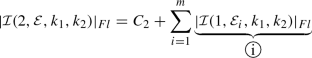
and
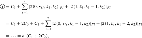
where we have denoted the vertices of the edge
 as \({\mathbf {v}}_{i1}\) and \({\mathbf {v}}_{i2}\). Hence,
In general, for \(d=2\) we deduce that
 (14)
(14) -
Set \(d=3\) and assume \(k_1 = \min \{k_1,k_2,k_3\}\), so that we may select \(x_{0,1} \ne 0\) and \(x_{0,2} = x_{0,3} = 0\) on each of the faces of \({\mathscr {P}} \). Thereby, employing Algorithm 1 we deduce that
where, for each \(i=1,\ldots ,m\),
Here, the computational complexity of
 depends on the choice of \({\mathbf {x}} _{0} \equiv {\mathbf {x}} _{0,ij}\) which defines the origin of the coordinate system for
  , \(j=1,\ldots ,m_i\), \(i=1,\ldots ,m\). According to Remark 4, two components of \({\mathbf {x}} _{0,ij}\) can possibly be different from zero, which implies that the complexity of Algorithm 1 increases exponentially when \(d=3\). However, it is possible to modify Algorithm 1 in order to avoid the double recursive calls which cause this exponential complexity. In particular, in Sect. 2.3 we propose an alternative algorithm which exploits the same idea of Algorithm 1 and allows us to overcome this issue.


 as
as 


 depends on the choice of
  ,
, 
Comparison of the number of FLOPs required to evaluate \(\int _{{\mathscr {P}}} x^{k_1} y^{k_2} \mathrm {d} \mathbf{x}\), based on fixing \(k_1\) and varying \(k_2 \in \{0,\ldots ,50\}\): a Quadrature free method A.1; b Sub-tessellation method A.3

Comparison of the number of FLOPs required to evaluate \(\int _{{\mathscr {P}}} x^{k} y^{k} \mathrm {d} \mathbf{x}\) as k increases employing both the quadrature free and sub-tessellation methods: a Excludes function evaluations; b Total cost including function evaluations
In order to confirm (14), we use the tool [56] to measure the number of FLOPs required to exactly compute \(\int _{{\mathscr {P}}} x^{k_1} y^{k_2} \mathrm {d} \mathbf{x}\); moreover, comparisons will also be made with A.3. To simplify the presentation, the polygon \({\mathscr {P}} \) is selected to be the triangle with vertices \((-1,0.3)\), \((1,-1)\), and (0.3, 1); thereby, A.3 does not require the computation of a sub-tessellation. In Fig. 6, we plot the number of FLOPs needed to evaluate \(\int _{{\mathscr {P}}} x^{k_1} y^{k_2}\mathrm {d} \mathbf{x}\) by fixing \(k_1\) and varying \(k_2 \in \{0,\ldots ,50\}\) employing both A.1 and A.3. In particular, Fig. 6a shows that the number of FLOPs required by the quadrature free method A.1 growths linearly with respect to \(k_2\) when \(k_1>k_2\) and becomes constant as \(k_2\) increases when \(k_1 \le k_2\). Figure 7 confirms the asymptotic behaviour of the two algorithms in the case when \(k_1=k_2\); here, the number of FLOPs required by the sub-tessellation method is reported in both the case when the cost of the evaluation of the quadrature nodes and weights employing the function gauleg, cf. [55], for example, is included/excluded. In particular, we show results both in the case when the cost of the function evaluations is excluded, cf. Fig. 7a, as well as the total number of FLOPs required by each algorithm to exactly evaluate \(\int _{{\mathscr {P}}} x^{k} y^{k}\mathrm {d} \mathbf{x}\), cf. Fig. 7b. As expected, the computational complexity of A.3 grows as \({\mathcal O}(k^2)\) and \({\mathcal O}(k^3)\) in these two latter cases, respectively, while the cost of the quadrature free method is always \({\mathcal O}(k)\) as k increases.
Thus far, the numerical results presented for the proposed quadrature free method have assumed that the points \({\mathbf {x}} _{0}\), which are used to define the origin of the coordinate system of each N-polytope  which defines the facets of \({\mathscr {P}} \), has been chosen in an optimal manner to ensure that the number of recursive calls of
  , cf. Algorithm 1, is minimized. Indeed, a sub-optimal choice of these points leads to an exponential growth in the number of recursive calls of the function
  in Algorithm 1. For example, if \(d=2\) the non-optimal choice of \({\mathbf {x}} _{0}\) implies that each call of
  with \(N = 1\) leads to a double recursive call of
  , up to when a zero exponent \(k_1\) or \(k_2\) appears as input. In particular, if \(k_1 = k_2 = k\), it is possible to show that the number of FLOPs required by the quadrature free method grows as \({\mathcal O}(2^{2k-1})\), as k increases, cf. Fig. 8. In the following section, we present an alternative implementation of the quadrature free algorithm which avoids this exponential growth, irrespective of the selection of the points \({\mathbf {x}} _0\).

Number of FLOPs required to evaluate \(\int _{{\mathscr {P}}} x^{k} y^{k} \mathrm {d} \mathbf{x}\) as k increases, based on employing the quadrature free method, with a sub-optimal choice of \({\mathbf {x}} _{0}\)

Number of FLOPs required to evaluate \(\{ \int _\kappa x^{k_1} y^{k_2} \mathrm {d} {\mathbf {x}} ~ \forall \ k_1,k_2 \ge 0, ~ k_1+k_2 \le p \}\) based on employing Algorithm 1 (with an optimal selection of the points \({\mathbf {x}} _0\)), and Algorithm 2
2.3 Integration of Families of Monomial Functions
In the context of employing the quadrature free approach within a finite element method, in practice we are not interested in integrating a single monomial function, but instead an entire family of monomials, which, for example, form a basis for the space of polynomials of a given degree over a given polytopic element \(\kappa \) which belongs to the underlying computational mesh. For example, when \(d=2\), let us consider the evaluation of
We note that even when employing the Approach A.1 with an optimal choice of the points \({\mathbf {x}} _{0}\), the total number of FLOPs required for the computation of (15) is approximately  , as p increases.
To improve the dependence on p we propose an alternative approach, cf. Algorithm 2; this is based on the observation that, using the notation of Algorithm 1, if the values of  , \(j=1,\ldots ,m\),
  , for \(1 \le N \le d-1\), in Algorithm 1, have already been computed, then the computation of
  is extremely cheap. Indeed, since we must store the integrals of all the monomials on \(\kappa \) anyway, we can start by computing and storing \(\int _{\kappa } x^{k_1} y^{k_2} \mathrm {d} x_1 \mathrm {d} x_2\) related to the lower degrees \(k_1,k_2\) and \(N=1\), then exploit these values in order to compute the integrals with higher degrees \(k_1,k_2\) and higher dimension N of the integration domain
  . This leads to an algorithm, whereby the number of FLOPs required to compute and store \(\{ \int _{\kappa } x_1^{k_1}\ldots x_d^{k_d}\mathrm {d} \sigma _d(x_1,\ldots ,x_d),\ k_1,\ldots ,k_d \ge 0, ~k_1+k_2+\cdots +k_d \le p \}\) is of order
  , as p increases, irrespective of the selection of choice of the points \({\mathbf {x}} _{0}\). In Fig. 9 we now compare these two approaches for \(d=2\), when the underlying element is selected to be the triangular region employed in the previous section. Here, we compare Algorithm 1, with an optimal selection of the points \({\mathbf {x}} _{0}\), with Algorithm 2, where in the latter case the points \({\mathbf {x}} _{0}\) are simply selected to be equal to the first vertex defining each edge; here, we clearly observe the predicted increase in FLOPs of
  and
and  , as p increases, for each of the two algorithms, respectively.

3 Application to hp-Version DG Methods
We consider the following elliptic model problem, given by: find u such that
where \(\varOmega \subset \mathbb {R}^d \), \(d = 2,3\), is a polygonal/polyhedral domain with boundary \(\partial \varOmega \) and f is a given function in \(L^2(\varOmega )\).
In order to discretize problem (16), we introduce a partition  of the domain \(\varOmega \), which consists of disjoint (possibly non-convex) open polygonal/polyhedral elements \(\kappa \) of diameter \(h_{\kappa }\), such that
  . We denote the mesh size of
 by
by  . Furthermore, we define the faces of the mesh
 as the planar/straight intersections of the \((d-1)\)-dimensional facets of neighbouring elements. This implies that, for \(d=2\), a face consists of a line segment, while for \(d=3\), the faces of
 are general shaped polygons; without loss of generality, for the definition of the proceeding DG method we assume that the faces are \((d-1)\)-dimensional simplices, cf. [24, 25] for a discussion of this issue. In order to introduce the DG formulation, it is helpful to distinguish between boundary and interior element faces, denoted by \({\mathcal {F}}_h^B\) and \({\mathcal {F}}_h^I\), respectively. In particular, we observe that \(F \subset \partial \varOmega \) for \(F \in {\mathcal {F}}_h^B\), while for any \(F \in {\mathcal {F}}_h^I\) we assume that \(F \subset \partial \kappa ^{\pm }\), where \(\kappa ^{\pm }\) are two adjacent elements in
  . Furthermore, we write \({\mathcal {F}}_h = {\mathcal {F}}_h^I \cup {\mathcal {F}}_h^B\) to denote the set of all mesh faces of
  . For simplicity of presentation we assume that each element
  possesses a uniformly bounded number of faces under mesh refinement, cf. [24, 25].
We associate to
 the corresponding discontinuous finite element space \(V_h\), defined by
  where
where  denotes the space of polynomials of total degree at most \(p_{\kappa } \ge 1\) on
  , cf. [24, 25].
In order to define the DG method, we introduce the jump and average operators:

where \(v^\pm \) and \(\varvec{\tau }^\pm \) denote the traces of sufficiently smooth scalar- and vector-valued functions v and \(\varvec{\tau }\), respectively, on F taken from the interior of \(\kappa ^\pm \), respectively, and \({\mathbf {n}}^\pm \) are the unit outward normal vectors to \(\partial \kappa ^\pm \), respectively, cf. [12].
We then consider the bilinear form  , corresponding to the symmetric interior penalty DG method, defined by

where \(\nabla _h\) denotes the broken gradient operator, defined elementwise, and  denotes the interior penalty stabilization function, whose precise definition, based on the analysis introduced in [24, 25], is given below. To this end, we first need the following definition.
Definition 1
Let  be the subset of elements
  such that each
  can be covered by at most
  shape-regular simplices
  , such that

for all  , for some
  , where \(C_{as}\) and \(c_{as}\) are positive constants, independent of \(\kappa \) and
  .
.
Given Definition 1, we recall the following inverse inequality, cf. [24, 25].
Lemma 2
Let  , \(F\subset \partial \kappa \) denote one of its faces, and
  be defined as in Definition 1. Then, for each
  , we have the inverse estimate
where

and \(\kappa _{\flat }^F\) denotes a d-dimensional simplex contained in \(\kappa \) which shares the face F with  . Furthermore, \(C_{inv}\) is a positive constant, which if
  depends on the shape regularity of the covering of \(\kappa \) given in Definition 1, but is always independent of \(| \kappa | / \sup _{\kappa _{\flat }^F \subset \kappa } | \kappa _{\flat }^F |,\ p_{\kappa }\) and v.
Based on Lemma 2, together with the analysis presented in [24, 25], the parameter \(\alpha _h\) can be defined as follows.
Definition 2
Let  be defined facewise by

with \(C_{\alpha }>C_{\alpha }^{min}\), where \(C_{\alpha }^{min}\) is a sufficiently large lower bound.
The DG discretization of the problem (16) is given by: find \(u_h \in V_h\) such that

By fixing a basis \(\{ \phi _i\}_{i=1}^{N_h}\), \(N_h\) denoting the dimension of the discrete space \(V_h\), (19) can be rewritten as: find \({\mathbf {U}} \in \mathbb {R}^{N_h}\) such that
where \({\mathbf {f}}_i = \int _{\varOmega } f\phi _i \mathrm {d} {\mathbf {x}}\ \forall i=1,\ldots ,N_h\), \({\mathbf {A}}\) is the stiffness matrix, given by  , \({\mathbf {M}}\) is the mass matrix, and \({\mathbf {U}}\) contains the expansion coefficients of \(u_h \in V_h\) with respect to the chosen basis. In order to assemble \(({\mathbf {A}} + {\mathbf {M}} )\) we need to compute the following matrices:

for \(i,j=1,\ldots ,N_h\), where as before \(N_h\) denotes the dimension of the DG space \(V_h\). In particular, the stiffness matrix related to the DG approximation of problem (19) is defined as \({\mathbf {A}} = {\mathbf {V}} - {\mathbf {I}}^\top - {\mathbf {I}} + {\mathbf {S}}\).
4 Elemental Stiffness and Mass Matrices
In this section, we outline the application of Algorithm 2 for the efficient computation of the mass and stiffness matrices appearing in (20).
4.1 Shape Functions for the Discrete Space \(V_h\)
To construct the discrete space \(V_h\) we exploit the approach presented in [25], based on employing polynomial spaces defined over the bounding box of each element. More precisely, given an element  , we first construct the Cartesian bounding box \(B_{\kappa }\), such that \(\overline{\kappa } \subset \overline{B_{\kappa }}\). Given
  , it is easy to define a linear map between \(B_{\kappa }\) and the reference element \(\hat{B} = (-1,1)^d\) as follow: \({\mathbf {F}}_{\kappa }: \hat{B} \rightarrow B_{\kappa } \text { such that } {\mathbf {F}}_{\kappa }: \hat{{\mathbf {x}}} \in \hat{B} \longmapsto {\mathbf {F}}_{\kappa }(\hat{{\mathbf {x}}}) = {\mathbf {J}}_{\kappa } \hat{{\mathbf {x}}} + {\mathbf {t}}_{\kappa },\) where \( {\mathbf {J}}_{\kappa } \in \mathbb {R}^{d \times d}\) is the Jacobi matrix of the transformation which describes the stretching in each direction, and \({\mathbf {t}}_{\kappa } \in \mathbb {R}^d \) is the translation between the point \({\mathbf {0}} \in \hat{B}\) and the baricenter of the bounded box \(B_{\kappa }\), see Fig. 10. We note that since \({\mathbf {F}}_{\kappa }\) affinely maps one bounding box to another (without rotation), the Jacobi matrix \({\mathbf {J}}_{\kappa }\) is diagonal.
Employing the map  , we may define a standard polynomial space
  on \(B_{\kappa }\) spanned by a set of basis functions \(\{ \phi _{i,\kappa } \}\) for
  . More precisely, we denote by
  the family of one-dimensional and \(L^2\)-orthonormal Legendre polynomials, defined over \(L^2(-1,1)\), i.e.,

cf. [40, 57]. We then define the basis functions for the polynomial space  as follows: writing \(I = (i_1,i_2,\ldots ,i_d)\) to denote the multi-index used to identify each basis function \(\{ \hat{\phi }_I \}_{0 \le | I | \le p}\), where \(| I | = i_1 + \cdots + i_d,\) we have that

Then, the basis functions for the polynomial space  are defined by using the map \({\mathbf {F}}_{\kappa }\), namely:
The set  forms a basis for the space \(V_h\). On each element
  we introduce a bijective relation between the set of multi-indices \(\{ I = (i_1,\ldots ,i_d): 0 \le | I | \le p_{\kappa } \}\) and the set \(\{ 1, 2, \ldots , N_{p_{\kappa }} \}\).
4.2 Volume Integrals Over Polytopic Mesh Elements
In the following we describe the application of Algorithm 2 to compute the entries in the local mass and element-based stiffness matrices
respectively, for all  . For simplicity of presentation, we restrict ourselves to two-dimensions, though we emphasize that the three-dimensional case is analogous, cf. Sect. 5.2 below. Since the basis functions are supported only on one element, employing the transformation \({\mathbf {F}}_{\kappa }\), we have
where in the last integral \(\hat{\kappa } = {\mathbf {F}}_{\kappa }^{-1}(\kappa ) \subset \hat{B}\), see Fig. 10. Here, the Jacobian of the transformation \({\mathbf {F}}_{\kappa }\) is given by \(|{\mathbf {J}}_{\kappa }| = ({\mathbf {J}}_{\kappa })_{1,1} ({\mathbf {J}}_{\kappa })_{2,2}\), which is constant, due to the definition of the map. In order to employ the homogeneous function integration method described in the previous section, we need to identify the coefficients of the homogeneous polynomial expansion for the function \(\hat{\phi }_i(\hat{x},\hat{y}) \hat{\phi }_j(\hat{x},\hat{y})\). We observe that  , and each one–dimensional Legendre polynomial can be expanded as


Example of a polygonal element  , the relative bounded box \(B_{\kappa }\), the map \({\mathbf {F}}_{\kappa }\) and \(\hat{\kappa } = {\mathbf {F}}_{\kappa }^{-1}(\kappa )\)
Therefore, we have
Here, we have written
Notice that the coefficients \({\mathcal {C}}_{i,j,k}\) can be evaluated, once and for all, independently of the polygonal element \(\kappa \). We now consider the general element of the volume matrix \({\mathbf {V}}_{i,j}\), cf. (24). Proceeding as before, let \(I,\ J\) be the two multi-indices corresponding respectively to i and j, we have

Proceeding as before, we apply a change of variables to the terms  and
and  with respect to the map \({\mathbf {F}}_{\kappa }\); thereby, we obtain

From the definition of \({\mathbf {F}}_{\kappa }\), the inverse map is given by \({\mathbf {F}}^{-1}_{\kappa }({\mathbf {x}}) = {\mathbf {J}}_{\kappa }^{-1} ({\mathbf {x}}- {\mathbf {t}}_{\kappa })\). Then, using the definition (23) of the basis functions, we have the following characterization of the partial derivatives appearing in the terms  and
and  :
:
where we have used that \(({\mathbf {J}}^{-1}_{\kappa })_{2,1} = ({\mathbf {J}}^{-1}_{\kappa })_{1,2} = 0\) since \({\mathbf {J}}_{\kappa }\) is diagonal. Then,  can be written as:

Since \(({\mathbf {J}}^{-1}_{\kappa })_{1,1}^2 | {\mathbf {J}}_{\kappa } |\) is constant, the integrand function of term  is a polynomial. Thereby, we have the following relation:

From the expansion (25) of the Legendre polynomials, we note that

where the indices \(C'_{i,m}=(m+1)C_{i,m+1}\) are the coefficients for the expansion of  . We deduce that
  if \(i_1 = 0\) or \(j_1 = 0\), and

where \({\mathcal {C}}_{i_2,j_2,l}\) is defined in (26), and
with \(C'_{i,n}=(n+1)C_{i,n+1}\), \(C'_{j,m}=(m+1)C_{j,m+1}\), cf. (28), is the expansion of the derivatives of the Legendre polynomials which is computable independently of the element \(\kappa \),  . Analogously, we deduce the following expression for the second term of Eq. (27):

4.3 Interface Integrals over Polytopic Mesh Elements
With regards the interface integrals appearing in Eq. (18), we describe the method by expanding the jump and average operators and computing each term separately, working, for simplicity, again in two-dimensions. Firstly, we discuss how to transform the integral over a physical face \(F \subset \partial \kappa \) to the corresponding integral over the face \(\hat{F} = {\mathbf {F}}_{\kappa }^{-1}(F) \subset \partial \hat{\kappa }\) on the reference rectangular element \(\hat{\kappa }\). To this end, let \(F \subset \partial \kappa \) be a face of the polygon \(\kappa \),  , and let \({\mathbf {x}} _1 = (x_1,y_1)\) and \({\mathbf {x}} _2=(x_2,y_2)\) denote the vertices of the face, based on counter clock-wise ordering of the polygon vertices. The face \(\hat{F} = {\mathbf {F}}_{\kappa }^{-1}(F)\) is identified by the two vertices \(\hat{{\mathbf {x}}} _1 = {\mathbf {F}}_{\kappa }^{-1}({\mathbf {x}})\) and \(\hat{{\mathbf {x}}} _2 = {\mathbf {F}}_{\kappa }^{-1}({\mathbf {x}} _2).\) For a general integrable function \(g:\kappa \rightarrow \mathbb {R}\) we have
where  and
and  is defined as
  where
where  is the unit outward normal vector to \(\hat{F}\).
We next describe how to compute the interface integrals. From the definition of the jump and average operators, cf. (17), on each edge  shared by the elements \(\kappa ^{\pm }\) we need to assemble
for \(i,j=1,\ldots ,N_{p_{\kappa ^{\pm }}}\). Analogously, on the boundary face  belonging to
  we only have to compute
for \(i,j=1,\ldots ,N_{p_{\kappa ^+}}\). We next show how to efficiently compute a term of the form
where I, J are the suitable multi-indices associated to \(i,j=1,\ldots ,N_{p_{\kappa ^+}}\), respectively. Proceeding as before, we have

Analogously, we have

For the term  , we directly apply the definition of the basis function, and obtain

while for the term  we have

In order to obtain a homogeneous polynomial expansion for  we have to write explicitly the composite map \(\tilde{{\mathbf {F}}}(\hat{{\mathbf {x}}}) = {\mathbf {F}}_{\kappa ^-}^{-1}({\mathbf {F}}_{\kappa ^+}(\hat{{\mathbf {x}}}))\). That is
where the matrix \(\tilde{{\mathbf {J}}}\) is diagonal since \({\mathbf {J}}^{-1}_{\kappa ^-}\) and \({\mathbf {J}}_{\kappa ^+}\) are diagonal. We then have

Combining (30) and (31), and denoting by \(\hat{F}^+ = {\mathbf {F}}_{\kappa ^+}^{-1}(F)\), cf. Fig. 11, from (29) we obtain

where  and
and  are defined as

Here, as before, \(C_{i,n}\) are the coefficients of the homogeneous function expansion of the Legendre polynomials in \((-1,1)\), while \(\tilde{X}_{j,m}\) and \(\tilde{Y}_{j,m}\) are defined by
here, we have exploited the Newton-binomial expansion of the terms \((\tilde{{\mathbf {J}}}_{1,1} \hat{x} + \tilde{{\mathbf {t}}}_1)^k\) and \((\tilde{{\mathbf {J}}}_{2,2} \hat{y} + \tilde{{\mathbf {t}}}_2)^l\) appearing in equation (31).

Example of a polygonal elements  , together with the bounded boxes \(B_{\kappa ^{\pm }}\), and the local maps \({\mathbf {F}}_{\kappa ^{\pm }}: \hat{\kappa } \rightarrow \kappa ^{\pm }\) for the common face \(F \subset \kappa ^{\pm }\)
Similar considerations allow us to compute

where \({\mathcal {C}}''_{i,j,k}\) are defined as
and where \({\mathbf {n}}^+ = [n_x^+, n_y^+]^\top \) is the unit outward normal vector to the physical face F from \(\kappa ^+\). Similarly,

where we have also introduced  and
and  defined as

Remark 5
The coefficients \(\tilde{X}\) and \(\tilde{Y}\) depend on the maps \({\mathbf {F}}_{\kappa ^+}\) and \({\mathbf {F}}_{\kappa ^-}\), as well as  and
and  ; thereby, they must be computed for each element \(\kappa \) in the mesh
  .
.
Remark 6
With regards the computation of the forcing term
we point out that the quadrature method proposed in this paper allows to exactly evaluate (32) when f is a constant or a polynomial function. If f is a general function, an explicit polynomial approximation of f is required.
5 Numerical Experiments
We present some two- and three-dimensional numerical experiments to test the practical performance of the proposed approach. Here, the results are compared with standard assembly algorithms based on employing efficient quadrature rules on a sub-tessellation.
5.1 Two-Dimensional Test Case
We test the performance of the algorithm outlined in Sect. 4 for the computation of the elemental mass and stiffness matrices resulting from the DG discretization (19) on Voronoi decompositions as shown in Fig. 12. In particular, we compare the CPU-time needed to assemble the local and global elemental matrices using Algorithm 2, cf. Sect. 4, with Quadrature Integration over polygonal domains, based on the sub-tessellation method on polygons and Gaussian line integration for the related interface terms. More precisely, given  , the sub-tessellation scheme on \(\kappa \) is performed by constructing a non-overlapping sub-tessellation \(\kappa _{{\mathscr {S}}} = \{ \tau _{\kappa } \}\) consisting of standard triangular elements; in particular, as, for our tests, we consider Voronoi numerical grids, we exploit the convexity of \(\kappa \) and define \(\kappa _{{\mathscr {S}}}\) by connecting the centre of mass of \(\kappa \) with its vertices. As an example, if we consider computing the elemental mass matrix \({\mathbf {M}}_{i,j}^{\kappa }\), we have that
where \({\mathbf {F}}_{\tau _\kappa }: \hat{\tau } \rightarrow \tau _\kappa \) is the mapping from the reference simplex \(\hat{\tau }\) to \(\tau _\kappa \), with Jacobian \(|{\mathbf {J}}_{\tau _\kappa }|\), and \(\{ (\varvec{\xi }_r, \omega _r) \}_{r=1}^{q_{\kappa }}\) denotes the quadrature rule defined on \(\hat{\tau }\). The construction of quadrature rules on \(\hat{\tau }\) may be computed based on employing the Duffy transformation, whereby the reference tensor-product element \((-1,1)^2\) is mapped to the reference simplex. As the algorithm outlined in Sect. 4 does not require the definition of quadrature nodes and weights, in the following we will refer to it as the Quadrature Free Method. Consider the problem (19) introduced in Sect. 3 with \(d=2\) and \(\varOmega = (0,1)^2\), where we select the set of basis functions \(\{ \phi _i \}_{i=1}^{N_h}\) for \(V_h\) as described in Sect. 4. In order to quantify the performance of the proposed approach, we consider a series of numerical tests obtained by varying the polynomial degree \(p_{\kappa }=p\) for all  , between 1 and 6 and by employing a series of uniform polygonal meshes of different granularity, cf. Fig. 12. The numerical grids are constructed based on employing PolyMesher, cf. [65]. Here, we are interested in the CPU time needed to assemble the matrices (21) and (22).

Example of Voronoi mesh on \(\varOmega =(0,1)^2\). a 50 elements. b 250 elements. c 1000 elements

Comparison of the CPU time needed to assemble the global matrices \({\mathbf {M}}\) and \({\mathbf {V}}\) for a two-dimensional problem by using the proposed quadrature free method and the classical sub-tessellation scheme. For each algorithm, each line is obtained by fixing the polynomial approximation degree \(p \in \{1,2,3\}\) (left) and \(p \in \{4,5,6\}\) (right), and measuring the CPU time by varying the number of elements in the underlying mesh. a Comparison for \(p \in \{1,2,3\}\). b Comparison for \(p \in \{4,5,6\}\)
In the first test case, we consider the CPU time needed to assemble the matrices \({\mathbf {M}}\) and \({\mathbf {V}}\). As pointed out in Sect. 4, these matrices are block diagonal and each block consists of an integral over each polygonal element  . In Fig. 13 we present the comparison between the CPU times needed to assemble the global matrices \({\mathbf {M}}\) and \({\mathbf {V}}\) based on employing the quadrature free method and quadrature integration (based on sub-tessellation) when varying the number of elements \(N_{e} \in \{ 64, 256, 1024, 4094, 16384, 65536\}\) and the polynomial degree \(p \in \{ 1,2,3\}\) (left), and \(p \in \{4,5,6\}\) (right). Clearly, our approach outperforms the classical sub-tessellation method leading to substantial gains in efficiency. For a more detailed comparison, we have presented in Fig. 15a the logarithmic-scaled graphs of each computation: from the results of Fig. 15a we observe that the CPU time grows like \(\mathcal{O}(N_e)\), as \(N_e\) increases, as expected.

Comparison of the CPU time needed to assemble the global matrices \({\mathbf {S}}\) and \({\mathbf {I}}\) for a two-dimensional problem by using the proposed quadrature free method and the classical Gauss line integration scheme. For each approach, each line is obtained by fixing the polynomial approximation degree \(p \in \{1,2,3\}\) (left) and \(p \in \{4,5,6\}\) (right), and measuring the CPU time by varying the number of elements in the underlying mesh. a Comparison for \(p \in \{1,2,3\}\). b Comparison for \(p \in \{4,5,6\}\)

Comparison between the CPU time needed by the two method to assemble the global matrices \({\mathbf {M}}\) and \({\mathbf {V}}\) (left) and \({\mathbf {S}}\) and \({\mathbf {I}}\) (right) for a three-dimensional problem, versus the number of elements and for different choices of \(p=3,\ldots ,6\) (log–log scale). a CPU time comparison needed to assemble \({\mathbf {M}}\) and \({\mathbf {V}}\) in log–log scale. b CPU time comparison needed to assemble \({\mathbf {S}}\) and \({\mathbf {I}}\) in log-log scale
We have repeated the same set of numerical experiments measuring the CPU times needed to assemble the face terms appearing in the matrices \({\mathbf {S}}\) and \({\mathbf {I}}\); these results are reported in Fig. 14. Here, the domains of integration of the integrals involved are the edges of the polygonal elements, which are simply line segments in the plane \({\mathbf {R}}^2\). Here, we compare the quadrature free method described in Sect. 4.3 with classical Gaussian line integration, where the integrating function is pointwise evaluated on the physical numerical nodes lying on each face. The graphs in Fig. 14a, b show the comparison between the CPU time taken for the two different approaches. Here, we again observe that significant computational savings are made when the proposed quadrature free method is employed, though the increase in efficiency is less than that attained for the computation of the volume integrals. In Fig. 15b we plot the logarithmic-scaled CPU time with respect to the number of mesh elements; again the CPU time grows as \(\mathcal{O}(N_e)\) as \(N_e\) increases.
Referring to Figs. 13 and 14, we observe that the cost of assembly of the matrices \({\mathbf {M}}\) and \({\mathbf {V}}\), which involve volume integrals over each element \(\kappa \) in the computational mesh  , is more expensive than the time it takes to assemble the face-based matrices \({\mathbf {S}}\) and \({\mathbf {I}}\), when the classical Gaussian line integration method is employed. This is, of course, due to the greater number of function evaluations required to compute \({\mathbf {M}}\) and \({\mathbf {V}}\) on the underlying sub-tessellation; note that in two-dimensions, a sub-tesellation of the faces is not necessary, since they simply consist of line segments. However, the opposite behaviour is observed when the quadrature free method is employed; in this case, the volume integrals can be very efficiently computed since the coefficients \(\mathcal{C}_{i,j,k}\) and \(\mathcal{C}'_{i,j,k}\) only need to be computed once, cf. Sect. 4.2. On the other hand, computing the face integrals present in \({\mathbf {S}}\) and \({\mathbf {I}}\) requires the evaluation of the coefficients
  , and
, and  , cf. Sect. 4.3, which must be computed for each face
  .
.
5.2 Three-Dimensional Test Case
We now consider the diffusion–reaction problem (19) with \(d=3\) and \(\varOmega = (0,1)^3\). The polyhedral grids employed for this test case are defined by agglomeration: starting from a fine partition  of \(\varOmega \) consisting of \(N_{fine}\) disjoint tetrahedrons \(\{ \kappa _{f}^i\}_{i=1}^{N_{fine}}\), such that \(\overline{\varOmega } = \cup _{i=1}^{N_{fine}} \overline{\kappa }_{f}^i\), a coarse mesh
  of \(\varOmega \) consisting of disjoint polyhedral elements \(\kappa \) can be defined such that

where  denotes the set of fine elements which forms \(\kappa \). Here, the agglomeration of fine tetrahedral elements is performed based on employing the METIS library for graph partitioning, cf., for example, [45, 46]. With this definition each polyhedral element is typically non-convex. For simplicity, we have considered only the case of simply connected elements. In this particular case, the faces of the mesh
  are the triangular intersections of two-dimensional facets of neighbouring elements. Figure 16 shows three examples of the polyhedral elements resulting from agglomeration.

Example of polyhedral elements  obtained by agglomeration of tetrahedrons. \(\kappa _1\) has 18 triangular faces, \(\kappa _2\) has 20 triangular faces and \(\kappa _3\) has 22 triangular faces. a Element \(\kappa _1\). b Element \(\kappa _2\). c Element \(\kappa _3\)

Comparison of the CPU time needed to assemble the global matrices \({\mathbf {M}}\) and \({\mathbf {V}}\) for a three-dimensional problem by using the proposed quadrature free method and the classical sub-tessellation method. For each approach, each line is obtained by fixing the polynomial approximation degree \(p \in \{1,2,3\}\) (left) and \(p \in \{4,5,6\}\) (right), and measuring the CPU time by varying the number of elements of the underlying mesh. a Comparison for \(p \in \{1,2,3\}\). b Comparison for \(p \in \{4,5,6\}\)

Comparison of the CPU time needed to assemble the global matrices \({\mathbf {S}}\) and \({\mathbf {I}}\) for a three–dimensional problem by using the proposed quadrature free method and the classical sub-tessellation method. For each approach, each line is obtained by fixing the polynomial approximation degree \(p \in \{1,2,3\}\) (left) and \(p \in \{4,5,6\}\) (right), and measuring the CPU time by varying the number of elements of the underlying mesh. a Comparison for \(p \in \{1,2,3\}\). b Comparison for \(p \in \{4,5,6\}\)

Comparison between the CPU time needed by the two method to assemble the global matrices \({\mathbf {M}}\) and \({\mathbf {V}}\) (left) and \({\mathbf {S}}\) and \({\mathbf {I}}\) (right) for a three-dimensional problem, versus the number of elements and for different choices of \(p=3,\ldots ,6\) (log–log scale). a CPU time comparison needed to assemble \({\mathbf {M}}\) and \({\mathbf {V}}\) in log–log scale. b CPU time comparison needed to assemble \({\mathbf {S}}\) and \({\mathbf {I}}\) in log–log scale
We perform a similar set of experiments as the ones outlined in Sect. 5.2 for the two-dimensional case. Again, we compare the CPU time required by the proposed quadrature free method with the quadrature integration/sub-tessellation approach to assemble the stiffness and mass matrices resulting from the DG discretization of problem (19). Numerical integration over a polyhedral domain is required to assemble the matrices \({\mathbf {M}}\) and \({\mathbf {V}}\), cf. (21), whereas for the computation of \({\mathbf {S}}\) and \({\mathbf {I}}\), cf. (22), a cubature rule over polygonal faces (here triangular shaped) is needed. In general, for three-dimensional problems the quadrature integration approach consists in the application of the sub-tessellation method both for volume and face integrals, although in this particular case no sub-tessellation is required for the face integrals, since they simply consist of triangular domains. Moreover, as in this case a sub-tessellation into tetrahedral domains is already given by the definition of the polyhedral mesh, the quadrature integration for volume integrals on a general agglomerated polyhedral element \(\kappa = \cup _{\kappa _{f}' \in {\mathscr {S}}_{\kappa }} \kappa _{f}'\) is realized by applying an exact quadrature rule on each tetrahedron \(\kappa _{f}' \in {\mathscr {S}}_{\kappa }\). The comparison of the CPU times for the two methods outlined here are presented for a set of agglomerated polyhedral grids where we vary the number of elements \(N_e \in \{ 5, 40, 320, 2560, 20480\}\), and the polynomial degree \(p \in \{ 1,2,3,4,5,6\}\). For each agglomerated polyhedral grid  we have chosen the corresponding fine tetrahedral grid
  such that the cardinality of the set \({\mathscr {S}}_{\kappa }\) appearing in (33) is
  . The results are shown in Fig. 17 for the computation of the matrices \({\mathbf {M}}\) and \({\mathbf {V}}\), and in Fig. 18 for the computation of matrices \({\mathbf {S}}\) and \({\mathbf {I}}\). Here, we observe analogous behaviour to the two-dimensional case: the quadrature free method substantially outperforms quadrature integration both for the computation of the volume and face integrals. We also have reported in Fig. 19 the logarithmic-scaled graphs of each computation, showing that, as expected, the gain in terms of CPU time attained by exploiting the proposed method is more evident here, with respect to the two-dimensional case, also for the face integrals.
6 Conclusions
In this article we have proposed a new approach for the numerical evaluation of the integrals required to assemble the mass and stiffness matrices arising from the DG discretization of diffusion–reaction problems, where the underlying mesh is composed of polygonal/polyhedral elements. Starting from the idea proposed in [27] for the integration of homogeneous functions, we have developed a cubature method which does not require the definition of a set of nodes and weights on the domain of integration, and allows for the exact integration of polynomial functions based on evaluating the integrand and its derivatives only at the vertices of the polytopal integration domain. This approach shows a remarkable gain in terms of CPU time with respect to classical quadrature rules, maintaining the same degree of accuracy. On the one hand, the number of computations is optimized, with respect to the polynomial degree of the integrand, and moreover less memory storage is required as no sub-tessellation and quadrature nodes and weights are required. With regards the three-dimensional tests presented in Sect. 5.2, we note that more substantial gains in terms of CPU time, with respect to classical approaches, can be obtained if the underlying grid is composed of pure (not agglomerated) polyhedral elements: firstly, this is because a sub-partition should be defined on the fly for each element, and secondly, as faces are not only triangles but possibly polygons of arbitrary shape, a sub-tessellation is needed also for surface integrals. The proposed technique is completely general and can be extended to several numerical methods based on discrete spaces defined on polygonal/polyhedral meshes, such as Virtual Element Methods, Mimetic Finite Differences, Hybrid High-Order Methods, Hybridizable Discontinuous Galerkin Schemes, and Polygonal Finite Element Methods, for example. We stress that for moderate polynomial degrees, the proposed integration technique, which involves exact integration of bivariate and trivariate functions in two- and three-dimensions, respectively, has been observed to be numerically stable.
References
Antonietti, P.F., Brezzi, F., Marini, L.D.: Bubble stabilization of discontinuous Galerkin methods. Comput. Methods Appl. Mech. Eng. 198(21–26), 1651–1659 (2009)
Antonietti, P.F., Cangiani, A., Collis, J., Dong, Z., Georgoulis, E.H., Giani, S., Houston, P.: Review of discontinuous Galerkin Finite Element Methods for partial differential equations on complicated domains, Lecture Notes in Computational Science and Engineering, vol. 114, 1st edn., chap. 8, pp. 281–310. Springer (2016)
Antonietti, P.F., Facciolà, C., Russo, A., Verani, M.: Discontinuous Galerkin approximation of flows in fractured porous media. Technical Report 22/2016, MOX Report (2016)
Antonietti, P.F., Formaggia, L., Scotti, A., Verani, M., Verzott, N.: Mimetic Finite Difference approximation of flows in fractured porous media. ESAIM Math. Model. Numer. Anal. 50(3), 809–832 (2016)
Antonietti, P.F., Giani, S., Houston, P.: \(hp\)-version Composite Discontinuous Galerkin methods for elliptic problems on complicated domains. SIAM J. Sci. Comput. 35(3), A1417–A1439 (2013)
Antonietti, P.F., Giani, S., Houston, P.: Domain decomposition preconditioners for discontinuous Galerkin methods for elliptic problems on complicated domains. J. Sci. Comput. 60(1), 203–227 (2014)
Antonietti, P.F., Houston, P., Pennesi, G.: Fast numerical integration on polytopic meshes with applications to discontinuous Galerkin finite element methods. MOX Report No. 03/2018 (2018)
Antonietti, P.F., Manzini, G., Verani, M.: The fully nonconforming Virtual Element Method for biharmonic problems. Math. Mod. Methods Appl. Sci. (Accepted: 16 October 2017)
Antonietti, P.F., Pennesi, G.: V-cycle multigrid algorithms for discontinuous Galerkin methods on non-nested polytopic meshes. MOX Report No. 49/2017 (submitted 2017)
Antonietti, P.F., da Veiga, L.B., Mora, D., Verani, M.: A stream Virtual Element formulation of the Stokes problem on polygonal meshes. SIAM J. Numer. Anal. 52(1), 386–404 (2014)
Antonietti, P.F., da Veiga, L.B., Scacchi, S., Verani, M.: A C1 Virtual Element Method for the Cahn–Hilliard equation with polygonal meshes. SIAM J. Numer. Anal. 54(1), 34–56 (2016)
Arnold, N.D., Brezzi, F., Cockburn, B., Marini, L.D.: Unified analysis of discontinuous Galerkin methods for elliptic problems. SIAM J. Numer. Anal. 39(5), 1749–1779 (2001/2002)
Ayuso de Dios, B., Lipnikov, K., Manzini, G.: The nonconforming Virtual Element Method. ESAIM Math. Model. Numer. Anal. 50(3), 879–904 (2016)
Bassi, F., Botti, L., Colombo, A.: Agglomeration-based physical frame dG discretizations: an attempt to be mesh free. Math. Mod. Methods Appl. Sci. 24(8), 1495–1539 (2014)
Beirão da Veiga, L., Brezzi, F., Cangiani, A., Manzini, G., Marini, L.D., Russo, A.: Basic principles of Virtual Element Methods. Math. Models Methods Appl. Sci. 23(1), 199–214 (2013)
Beirão da Veiga, L., Brezzi, F., Marini, L.D., Russo, A.: Mixed Virtual Element Methods for general second order elliptic problems on polygonal meshes. ESAIM Math. Model. Numer. Anal. 50(3), 727–747 (2016)
Beirão da Veiga, L., Brezzi, F., Marini, L.D., Russo, A.: Virtual Element Method for general second-order elliptic problems on polygonal meshes. Math. Models Methods Appl. Sci. 26(4), 729–750 (2016)
Beirão da Veiga, L., Lipnikov, K., Manzini, G.: The Mimetic Finite Difference Method for Elliptic Problems, vol. 11. Springer, Cham (2014)
Brezzi, F., Lipnikov, K., Shashkov, M.: Convergence of the Mimetic Finite Difference method for diffusion problems on polyhedral meshes. SIAM J. Numer. Anal. 43(5), 1872–1896 (electronic) (2005)
Brezzi, F., Lipnikov, K., Shashkov, M.: Convergence of Mimetic Finite Difference method for diffusion problems on polyhedral meshes with curved faces. Math. Mod. Methods Appl. Sci. 16(2), 275–297 (2006)
Brezzi, F., Lipnikov, K., Simoncini, V.: A family of Mimetic Finite Difference methods on polygonal and polyhedral meshes. Math. Mod. Methods Appl. S. 15(10), 1533–1551 (2005)
Cangiani, A., Dong, Z., Georgoulis, E.H.: \(hp\)-Version space–time discontinuous Galerkin methods for parabolic problems on prismatic meshes. SIAM J. Sci. Comput. 39(4), A1251–A1279 (2017)
Cangiani, A., Dong, Z., Georgoulis, E.H., Houston, P.: \(hp\)-Version discontinuous Galerkin methods for advection-diffusion-reaction problems on polytopic meshes. ESAIM Math. Model. Numer. Anal. 50, 699–725 (2016)
Cangiani, A., Dong, Z., Georgoulis, E.H., Houston, P.: \(hp\)-Version discontinuous Galerkin methods on polygonal and polyhedral meshes. Springer International Publishing, SpringerBriefs in Mathematics, Berlin (2017)
Cangiani, A., Georgoulis, E.H., Houston, P.: \(hp\)-Version discontinuous Galerkin methods on polygonal and polyhedral meshes. Math. Models Methods Appl. Sci. 24(10), 2009–2041 (2014)
Cangiani, A., Manzini, G., Sutton, O.J.: Conforming and nonconforming Virtual Element Methods for elliptic problems. IMA J. Numer. Anal. 37(3), 1317–1354 (2017)
Chin, E.B., Lasserre, J.B., Sukumar, N.: Numerical integration of homogeneous functions on convex and nonconvex polygons and polyhedra. Comput. Mech. 56(6), 967–981 (2015)
Chin, E.B., Lasserre, J.B., Sukumar, N.: Modeling crack discontinuities without element-partitioning in the extended finite element method. Int. J. Numer. Methods Eng. 110(11), 1021–1048 (2017)
Cockburn, B., Dond, B., Guzmán, J.: A superconvergent LDG-hybridizable Galerkin method for second-order elliptic problems. Math. Comput. 77(264), 1887–1916 (2008)
Cockburn, B., Gopalakrishnan, J., Lazarov, R.: Unified hybridization of discontinuous Galerkin, mixed, and continuous Galerkin methods for second order elliptic problems. SIAM J. Numer. Anal. 47(2), 1319–1365 (2009)
Cockburn, B., Gopalakrishnan, J., Sayas, F.J.: A projection-based error analysis of HDG methods. Math. Comput. 79(271), 1351–1367 (2010)
Cockburn, B., Guzmán, J., Wang, H.: Superconvergent discontinuous Galerkin methods for second-order elliptic problems. Math. Comput. 78(265), 1–24 (2009)
Di Pietro, D.A., Ern, A.: A hybrid high-order locking-free method for linear elasticity on general meshes. Comput. Methods Appl. Mech. Eng. 283(1), 1–21 (2015)
Di Pietro, D.A., Ern, A.: Hybrid High-Order methods for variable-diffusion problems on general meshes. C. R. Math. Acad. Sci. Soc. R. Can. 353(1), 31–34 (2015)
Di Pietro, D.A., Ern, A., Lemaire, S.: An arbitrary-order and compact-stencil discretization of diffusion on general meshes based on local reconstruction operators. Comput. Method Appl. Math. 14(4), 461–472 (2014)
Droniou, J., Eymard, R., Herbin, R.: Gradient schemes: generic tools for the numerical analysis of diffusion equations. ESAIM Math. Model. Numer. Anal. 50(3), 749–781 (2016)
Fries, T.P., Belytschko, T.: The extended/generalized finite element method: an overview of the method and its applications. Int. J. Numer. Methods Eng. 84(3), 253–304 (2010)
Gerstenberger, A., Wall, A.W.: An Extended Finite Element Method/Lagrange multiplier based approach for fluid-structure interaction. Comput. Methods Appl. Mech. Eng. 197(19–20), 1699–1714 (2008)
Giani, S., Houston, P.: Domain decomposition preconditioners for discontinuous Galerkin discretizations of compressible fluid flows. Numer. Math. Theory Methods Appl. 7(2), 123–148 (2014)
Griffiths, D.J.: Introduction to Quantum Mechanics. Pearson Education, London (2005)
Hackbusch, W., Sauter, S.A.: Composite Finite Elements for problems containing small geometric details. Part II: Implementation and numerical results. Comput. Visual Sci. 1(4), 15–25 (1997)
Hackbusch, W., Sauter, S.A.: Composite Finite Elements for the approximation of PDEs on domains with complicated micro-structures. Numer. Math. 75(4), 447–472 (1997)
Holdych, D.J., Noble, D.R., Secor, R.B.: Quadrature rules for triangular and tetrahedral elements with generalized functions. Int. J. Numer. Methods Eng. 73(9), 1310–1327 (2015)
Hyman, J., Shashkov, M., Steinberg, S.: The numerical solution of diffusion problems in strongly heterogeneous non-isotropic materials. J. Comput. Phys. 132(1), 130–148 (1997)
Karypis, G., Kumar, V.: A fast and high quality multilevel scheme for partitioning irregular graphs. SIAM J. Sci. Comput. 20(1), 359–392 (1998)
Karypis, G., Kumar, V.: Metis: Unstructured graph partitioning and sparse matrix ordering system, version 4.0. http://www.cs.umn.edu/~metis (2009)
Lasserre, J.B.: Integration on a convex polytope. Proc. Am. Math. Soc. 126(8), 2433–2441 (1998)
Li, C.J., Lambertu, P., Dagnino, C.: Numerical integration over polygons using an eight-node quadrilateral spline finite element. J. Comput. Appl. Math. 233(2), 279–292 (2009)
Lyness, J.N., Monegato, G.: Quadrature rules for regions having regular hexagonal symmetry. SIAM J. Numer. Anal. 14(2), 283–295 (1977)
Ma, J., Rokhlin, V., Wandzura, S.: Generalized Gaussian quadrature of systems of arbitrary functions. SIAM J. Numer. Anal. 33(3), 971–996 (1996)
Moës, N., Dolbow, J., Belytschko, T.: A finite element method for crack growth without remeshing. Int. J. Numer. Methods Eng. 46(1), 131–150 (1999)
Mousavi, S.E., Sukumar, N.: Numerical integration of polynomials and discontinuous functions on irregular convex polygons and polyhedrons. Comput. Mech. 47(5), 535–554 (2011)
Mousavi, S.E., Xiao, H., Sukumar, N.: Generalized Gaussian quadrature rules on arbitrary polygons. Internat. J. Numer. Methods Eng. 82(1), 99–113 (2010)
Natarajan, S., Bordas, S., Mahapatra, D.R.: Numerical integration over arbitrary polygonal domains based on Schwarz–Christoffel conformal mapping. Int. J. Numer. Methods Eng. 80(1), 103–134 (2009)
Press, W.H., Teukolsky, S.A., Vetterling, W.T., Flannery, B.P.: Numerical Recipes 3rd Edition: The Art of Scientific Computing, 3rd edn. Cambridge University Press, New York (2007)
Qian, H.: Counting the floating point operations (flops). https://it.mathworks.com/matlabcentral/fileexchange/50608-counting-the-floating-point-operations--flops- (2015)
Quarteroni, A., Sacco, R., Saleri, F.: Numerical Mathematics. Springer, Berlin (2007)
Simon, C.P., Blume, L.E.: Mathematics for Economists. W. W. Norton and Company, New York (1996)
Sommariva, A., Vianello, M.: Product Gauss cubature over polygons based on Green’s integration formula. BIT 47(2), 441–453 (2007)
Stroud, A.H., Secrest, D.: Gaussiam quadrature formulas. ZAMM Z. Angew. Math. Mech. 47(2), 138–139 (1967)
Sudhakar, Y., Wall, W.A.: Quadrature schemes for arbitrary convex/concave volumes and integration of weak form in enriched partition of unity methods. Comput. Methods Appl. Mech. Eng. 258(1), 39–54 (2013)
Sukumar, N., Moës, N., Belytschko, T.: Extended Finite Element Method for three-dimensional crack modelling. Int. J. Numer. Methods Eng. 48(11), 1549–1570 (2000)
Sukumar, N., Tabarraei, A.: Conforming polygonal finite elements. Int. J. Numer. Methods Eng. 61(12), 2045–2066 (2004)
Tabarraei, A., Sukumar, N.: Extended Finite Element Method on polygonal and quadtree meshes. Comput. Methods Appl. Mech. Eng. 197(5), 425–438 (2008)
Talischi, C., Paulino, G.H., Pereira, A., Menezes, I.F.M.: Polymesher: a general-purpose mesh generator for polygonal elements written in matlab. Struct. Multidiscip. Optim. 45(3), 309–328 (2012)
Taylor, M.E.: Partial Differential Equations: Basic Theory. Springer, New York (1996)
Ventura, G.: On the elimination of quadrature subcells for discontinuous functions in the extended finite-element method. Int. J. Numer. Methods Eng. 66(5), 761–795 (2006)
Ventura, G., Benvenuti, E.: Equivalent polynomials for quadrature in Heaviside function enriched elements. Int. J. Numer. Methods Eng. 102(3–4), 688–710 (2015)
Xiao, H., Gimbutas, Z.: A numerical algorithm for the construction of efficient quadrature rules in two and higher dimensions. Comput. Math. Appl. 59(2), 663–676 (2010)
Yarvin, N., Rokhlin, V.: Generalized Gaussian quadratures and singular value decompositions of integral operators. SIAM J. Sci. Comput. 20(2), 669–718 (1998)
Yogitha, A.M., Shivaram, K.T.: Numerical integration of arbitrary functions over a convex and non convex polygonal domain by eight noded linear quadrilateral finite element method. Aust. J. Basic Appl. Sci. 10(16), 104–110 (2016)
Author information
Authors and Affiliations
Corresponding author
Additional information
Paola F. Antonietti and Giorgio Pennesi have been partially funded by the SIR Project No. RBSI14VT0S funded by MIUR - Italian Ministry of Education, Universities and Research—and by Fondazione Cariplo and Regione Lombardia research Grant No. 2015-0182. Paola F. Antonietti and Giorgio Pennesi also acknowledge the financial support given by GNCS-INdAM.
Rights and permissions
Open Access This article is distributed under the terms of the Creative Commons Attribution 4.0 International License (http://creativecommons.org/licenses/by/4.0/), which permits unrestricted use, distribution, and reproduction in any medium, provided you give appropriate credit to the original author(s) and the source, provide a link to the Creative Commons license, and indicate if changes were made.
About this article

Cite this article
Antonietti, P.F., Houston, P. & Pennesi, G. Fast Numerical Integration on Polytopic Meshes with Applications to Discontinuous Galerkin Finite Element Methods. J Sci Comput 77, 1339–1370 (2018). https://doi.org/10.1007/s10915-018-0802-y
Received:
Revised:
Accepted:
Published:
Issue Date:
DOI: https://doi.org/10.1007/s10915-018-0802-y