
Abstract
Freeze fracture depends on the property of frozen tissues or cells, when cracked open, to split along the hydrophobic interior of membranes, thus revealing broad panoramas of membrane interior. These large panoramas reveal the three-dimensional contours of membranes making the methods well suited to studying changes in membrane architecture. Freshly split membrane faces are visualized by platinum or tungsten shadowing and carbon backing to form a replica that is then cleaned of tissue and imaged by TEM. Etching, i.e., removal of ice from the frozen fractured specimen by sublimation prior to shadowing, can also reveal the true surfaces of the membrane as well as the extracellular matrix and cytoskeletal networks that contact the membranes. Since the resolution of detail in the metal replicas formed is 1–2 nm, these methods can also be used to visualize macromolecules or macromolecular assemblies either in situ or displayed on a mica surface. These methods are available for either specimens that have been chemically fixed or specimens that have been rapidly frozen without chemical intervention.
Key words
1 Introduction
1.1 History
Although metal shadowing had been used in the 1940s to visualize biological materials in the transmission electron microscope [1–5], it was not until 1957 that Russell Steere published the first accounts of his development of a device that could fracture a frozen specimen and then metal shadow the fractured surface [6, 7]. Following Steere’s innovation, Stanley Bullivant developed a similar device [8, 9] and Hans Moor, working with Balzers AG in Lichtenstein, was able to design a unit that went into commercial production [10–13]. The Balzers BAF 400D instrument, a descendent of these early models, is illustrated in Fig. 1a and includes an under table pumping system with control panels and an above table vacuum chamber and control units for the specimen pedestal and electron beam guns. Manufacture of the Balzers unit was taken over by Baltec and then by Leica in 2008, the unit becoming the Leica EM BAF 060 (see Fig. 1b). Since 1990, a number of freeze fracture units have become available [14] and both the Leica EM BAF 060 and the JEOL JFD II (see Fig. 1c) units are in common use today.

Freeze fracture units. (a) The Balzers BAF 400. This model was available either with an oil diffusion pump (400D) or a turbomolecular pump (400T). (b) The Leica BAF 060 which is equipped with a turbomolecular pump. (c) The JEOL JFD II. This unit formerly used a turbomolecular pump but is now available from RMC/Boeckeler fitted with a cryopump. (b) is a courtesy of Leica Microsystems; (c) is reproduced by copyright permission from JEOL
The Balzers unit went through a number of design generations over a period of 40 years resulting in a robust instrument consisting of the following components (see Fig. 2): (1) A vacuum chamber in which both specimen fracturing and metal shadowing takes place, (2) A specimen pedestal plumbed with liquid nitrogen flow through so as to maintain the specimen temperature between −130 °C and −80 °C, (3) A liquid nitrogen cooled knife, knife holder and microtome capable of fracturing the specimen at a series of depths, (4) Electron beam guns for atomization and deposition of platinum-carbon and carbon coatings on the fractured specimen, (5) A high voltage power supply to control electron beam gun deposition, and (6) A pumping system for the chamber consisting of an oil diffusion pump or turbomolecular pump in series with and backed by a mechanical pump. Further features that improved its use included a specimen pedestal for rotary shadowing, a quartz crystal monitor for real time measurement of metal and carbon deposition on the specimen, and a liquid nitrogen-cooled shroud to scavenge water vapor in the vicinity of the specimen.

Design of a typical freeze fracture unit—the Balzers BAF 400D. (a) Front door to the vacuum chamber with binocular microscope and specimen viewing window. (b) Diagram showing the major components and utilities within the vacuum chamber. (c) The pumping system below the chamber consisting of a mechanical pump and diffusion pump in series. (b) is modified from Chandler and Robertson [67]
All freeze fracture units today incorporate additional improvements over this basic design. Many machines include separate air locks for accessing the electron beam guns during refurbishing. In addition, vacuum locks for reloading specimens and changing knives are also used to further increase specimen throughput.
Initially, the freeze fracture process was thought to split ice away from membrane surfaces but with the work of Branton [15–17], it was demonstrated that the cleavage plane traveled through the hydrophobic interior of bilayer membranes with the result that two surfaces were revealed: the hydrophobic surface of the outer monolayer, referred to as the “E” or “extracellular” face, and the hydrophobic surface of the inner, or cytoplasmic monolayer, referred to as the “P” or “protoplasmic” face [18]. This terminology is straight forward when applied to the plasma membrane, but when applied to organellar membranes is consistent in that “P” face always refers to the hydrophobic surface of the monolayer in contact with the cytoplasm while “E” face always refers to the hydrophobic surface of the monolayer facing away from the cytoplasm.
Visualization of the fracture faces by metal shadowing was achieved by platinum-carbon atomization, initially by resistance guns and later by electron beam guns which accelerated and directed the metal atoms to the fractured surface at a specific angle, typically 45°. The platinum recrystallized on the frozen surface to form a thin layer of metal “islands” whose density and thickness varied with the topology of the facture face. In this manner, the three-dimensional nature of the replica can be appreciated even when viewed face on during microscopy. Figure 3a depicting a sea urchin egg cortex, demonstrates this effect when platinum is applied from a single direction so as to produce shadows (white in the microscope but black here in negative images) and a range of platinum densities that reveal a single layer of cortical secretory granules just under the plasma membrane. Comparison with a thin section of the same region (see Fig. 3b) reveals that the fractured surface follows the plasma and granule membranes thus revealing membrane architecture difficult to visualize in sections. Closer inspection of the plasma membrane faces demonstrates that the “P” face and “E” face are decorated with differing densities of intramembrane particles (IMPs) and that the stumps of cross-fractured microvilli are seen in the “P” face (see Fig. 3c) while corresponding microvillar indentations are seen in the “E” face (see Fig. 3d). Intramembrane particles were postulated to represent transmembrane proteins that upon fracturing are retained in one monolayer and extracted from the complimentary monolayer, leaving a hole that is quickly obliterated by deposition of water vapor [19]. Confirming evidence for this hypothesis came when Branton demonstrated that the reconstitution of erythrocyte band 3 protein in liposomes resulted in the appearance of IMPs in the liposome fracture faces [20].

The sea urchin egg cortex seen in thin section and freeze fracture replicas. (a) Platinum replica of the egg cortex showing cortical secretory granules lying just under the plasma membrane. (b) Thin section of the egg cortex revealing short microvilli on the egg surface and the onion-like internal matrix of the secretory granules. (c) The “P” face of the plasma membrane displaying stump-like remnants of fractured microvilli extending from the egg surface. (d) The “E” face of the plasma membrane incorporates invaginations leading to the interior of microvilli. Note that all images of platinum replicas in this chapter (excepting Fig. 8) are negative images. As seen directly on the electron microscope, shadows lack platinum and appear white. One can electronically reverse these to produce negative images in which platinum deposits appear white and shadows black. In this respect, negative images are similar to scanning electron micrographs and provide improved three-dimensional recognition by our visual system. Scale bars a, b = 0.5 μm; c, d = 0.1 μm. All panels are reproduced from Chandler and Heuser [24], with the permission of the Rockefeller University Press
Freeze fracture methodology has grown to include a large array of techniques. The diversity of techniques is mainly due to a large number of approaches in how the specimen is frozen, to the variety of shadowing procedures used, and to the different degrees of ice sublimation (“etching”) that can be employed. In addition, techniques ancillary to electron microscopy such as cytochemistry, immunocytochemistry, and tomography have been successfully employed in combination with freeze fracture and replica production. Table 1 outlines this variety of techniques that make freeze fracture a versatile tool in the electron microscopist’s arsenal. An overview of the evolution of freeze fracture and freeze etching techniques has been prepared recently by Heuser [21].
1.2 Freeze Fracture Techniques
1.2.1 Standard Procedures with Glutaraldehyde-Fixed Tissues
Developed over a period of years, the standard procedure is to chemically fix small tissue pieces with aldehydes, glycerinate for cryoprotection, freeze in a metal specimen carrier, and mount on a brass table that is inserted into the freeze fracture unit. An excellent overview of standard tissue preparation techniques for freeze fracture is available [22]. Because freezing of tissue leads to growth of ice crystals that distort cellular structure at the electron microscopic level, tissues must be cryoprotected by infiltration with high concentrations of glycerol (25–35 % v/v), with the result that many more ice crystals are nucleated but their growth is slow thereby resulting in an extremely fine granularity that does not disrupt structure. It was quickly learned that glycerination without prior chemical fixation of the tissue results in artifactual membrane blebbing and IMP redistribution [23]. Therefore, tissue is typically fixed with glutaraldehyde before glycerination and freezing. Use of osmium tetroxide as a fixative, while common in material embedded in epoxy resin and sectioned, is not compatible with the freeze fracture process because it prevents membrane splitting and formation of panoramic membrane faces. Small tissue cubes or pellets of isolated cells, fixed and glycerinated, are placed on gold–nickel alloy carriers shaped like top hats, and then frozen in a liquid cryogen. Liquid nitrogen is unsuitable as a cryogen because its ability to absorb heat is small and its boiling point is too low. As a result, it boils and forms an insulating layer of gas around the specimen resulting in very slow freezing and growth of relatively large ice crystals even in glycerinated specimens. For many years dichlorodifluoro-methane (Freon 12) was the cryogen of choice until its discovery as an ozone layer depleting agent and removal from the market. Although, Freon replacements such as R-22 and R134a are in use, R-22 is also ozone depleting and due to be phased out by 2020 and R134a is thought to contribute to greenhouse warming; both have gone largely untested in their possible use as a cryogen for freeze fracture work. Thus, the two most common cryogens currently in use are small hydrocarbons such as liquid propane or a nitrogen slush. Traditional freezing of specimens by plunging into liquid nitrogen-cooled cryogen is done by handheld tweezers. Alternatively, machines are now available such as the Leica EM GP, the Leica EM CPC, the EMS-002 or the Gatan Cryoplunge 3 that provide for automated plunging of grids and freeze fracture specimens into liquid propane. Alternatively, nitrogen slush can be generated by repeated evacuation of liquid nitrogen with a either a common mechanical pump or a dedicated instrument such as the Vit-Master in which boiling of the liquid extracts heat to produce a semisolid slush.
Fracturing of the frozen specimen is typically carried out in a vacuum of 2 × 10⁻⁶ mbar with the specimen temperature being held at −130 °C. Immediate shadowing of the freshly cleaved specimen from an angle of 45° with platinum (“unidirectional shadowing”) followed by carbon to strengthen the replica, results in clean membrane faces framed by smooth ice surfaces that have not been etched as seen in Fig. 4a. In this figure, note that some membrane surfaces can be difficult to distinguish from the surrounding cytoplasmic ice. In contrast, if the specimen is held at −110 °C and allowed to “etch” for 15–30 s between fracturing and shadowing, a modest amount of ice is sublimated leaving a rough patina on the non-membrane surfaces. This allows one to easily distinguish smooth membrane surfaces from roughened ice surfaces. As shown in Fig. 4b, in which a sea urchin egg cortical granule (cg) is undergoing fusion with the plasma membrane (pm), this rough patina identifies the aqueous pores formed during exocytosis. In Fig. 4c, these roughened aqueous pores can be distinguished from pores covered by a membrane diaphragm (arrows) which represent an interesting intermediate structure in the pore forming process [24]. The usefulness of etching standard specimens is limited, however, because deep etching of specimens prepared by the standard protocol is not possible due to the low vapor pressure of the glycerol cryoprotectant.

Mild etching allows ice and membrane faces to be distinguished. (a) Granule membranes in a rapidly frozen mast cell are not easily distinguished from unetched cytoplasmic ice. (b) Aqueous pores joining plasma (pm) and granule (cg) membranes in a chemically fixed sea urchin egg are easily identified by their rough patina created by brief etching. (c) In the same specimen, etched aqueous pores are easily distinguished from pores covered by a membrane diaphragm (arrows). Bars = 0.1 μm. (b) and (c) are reproduced from Chandler and Heuser [24], with the permission of the Rockefeller University Press
1.2.2 Specimens Rapidly Frozen Without Chemical Fixation or Cryoprotection
In order to avoid ice crystal damage of electron microscopic specimens that have not been cryoprotected, freezing rates of at least −50,000 °C per second must be used [25]. These rates can be achieved by several different means. Very thin specimens such as cells cultured on dialysis membrane can be frozen by manually plunging into liquid propane (see Fig. 5a) or by using an automated machine as described in the previous section. Alternatively, cell suspensions or tissues no greater than 50 μm thick can be housed between copper planchets that are sprayed with liquid propane in a propane jet freezer such as the RMC MF-7200 (Fig. 5b) designed by Staehelin and Gilkey [26] or the Balzers JFD30. In contrast, relatively thick specimens can be frozen by being pressed against a liquid-helium or liquid nitrogen-cooled copper block, a process known as “slam freezing” or “cold metal block freezing.” This process can be carried out by any one of several machines built for this purpose: the “CryoPress” designed by John Heuser [27], the Life-Cell metal block freezer (now out of production) and the Leica EM MM80 E that is still produced (see Fig. 5c). Finally, one can utilize high pressure freezing in which specimens up to 1 mm3 are enclosed in a planchet that is subjected to 2,100 bar pressure while being frozen with liquid nitrogen [28, 29]. This process can be carried out by a number of commercial units such as the Balzers/Baltec HPM 010, now the Leica EM HPM100 as described in the companion chapter on high pressure freezing.

Three types of instruments used for rapid freezing. (a) Liquid nitrogen-cooled bath of propane for manual plunge freezing. (b) RMC/Boeckeler Propane Jet Freezer that aims liquid propane under pressure at both sides of a metal specimen carrier. (c) Leica EM MM80 E Cold Metal Block Freezer in which a tissue face is rapidly pressed against a gold-plated copper block cooled by liquid nitrogen. (a) is reproduced from Chandler and Roberson [67]; (b) is reproduced with the permission of Boeckeler, Inc.; (c) is courtesy of Leica Microsystems, Inc.
Specimens rapidly frozen without chemical fixation or glycerination, when fractured and replicated unidirectionally with platinum, exhibit smooth membranes that are free of membrane blebs and wrinkles that are generally seen in glutaraldehyde-fixed specimens and considered artifacts [30, 31]. In addition, since specimens are immobilized within milliseconds, ultrarapidly frozen specimens are capable of capturing extremely fast biological processes such as synaptic vesicle exocytosis and membrane fusion [24, 32–34].
1.2.3 Quick Freezing, Deep Etching, and Rotary Shadowing (QF-DE-RS)
Since rapidly frozen specimens are not glycerinated, extensive sublimation of ice can be achieved thereby revealing micron-deep layers of biological structure that are particularly useful in visualizing macromolecular assemblies in situ—that is, within the context of normal tissue structure. Although applicable to a wide variety of structural features, the organization of the cytoskeleton and the extracellular matrix are particularly striking examples of how this technique has contributed to our understanding of functional macromolecular assemblies [35–39]. The depth of etching in a specimen is related to the temperature and duration of etching. Quick-frozen specimens fractured at −110 °C and etched briefly will exhibit a roughened, somewhat granular ice surface in the cytoplasm such as seen in the cortex of a mast cell between the plasma membrane and the underlying secretory granule (see Fig. 6a). In contrast, etching for 5 min at −90 °C may reveal an extensive layer of intertwined microfilaments whose relative three-dimensional architecture demonstrates functional relationships (see Fig. 6b). Additional etching (up to 10 min at −85 °C), can remove up to 1 μm of ice from all aqueous surfaces, revealing embedded biological structures. In Fig. 6c, for example, deep etching has revealed the intricate network of extracellular filaments that make up the vitelline layer of the sea urchin egg, a layer that is instrumental in binding sperm just before they enter and fertilize the egg. If etching had not been carried out, all the structures above the fracture line (arrow) would have been hidden by extracellular ice. Deep etching is equally effective at revealing cytoskeletal networks in the cytoplasm. Figure 6d illustrates the apical brush border of the intestinal epithelium in which myosin-head decorated microfilaments forming the core of microvilli are anchored into a web of intermediate filaments below. Deep etching is usually combined with rotary shadowing in which the specimen is rotated by an electric motor at about 3 Hz while platinum is being applied at a relatively low angle, about 20°–30°, so as to get platinum into every nook and cranny of its complex topology.

Platinum replicas of rapidly frozen specimens prepared with various degrees of ice sublimation (etching). (a) A secretory granule just under the plasma membrane of a mast cell. Note that cytoplasmic and extracellular ice has not been etched. (b) A similar specimen in which moderate etching reveals a dense array of microfilaments in the cytoplasm and the true extracellular surface of the plasma membrane. (c) The sea urchin egg surface is decorated with a fish net-like vitelline layer to which sperm bind. All extracellular matrix structures above the fracture line (arrow) were exposed by 5 min of etching at −90 °C using the QF-DE-RS technique. (d) The apical cytoskeleton of an intestinal epithelial cell as visualized by the QF-DE-RS method. Bundles of microfilaments that form the core structure of microvilli meet the terminal web of filaments in the apical cytoplasm. Scale bars = 0.1 μm. (a) is reproduced from Chandler and Heuser [33], with the permission of the Rockefeller University Press.); (b) is reproduced from Chandler and Roberson [67]; (c) is reproduced from Chandler and Heuser [35], with the permission of the Rockefeller University Press; (d) is reproduced from Hirokawa and Heuser [38], with the permission of the Rockefeller University Press
1.2.4 Freeze Drying of Cell Fragments
Cell fragments adhering to a glass or mica surface can be freeze dried by extensive sublimation of ice carried out for long periods of time (10 min), at relatively high temperatures (−85 to −90 °C) in a freeze fracture unit at high vacuum. Cell fragments are typically produced by cell adhesion to a surface then the cell sheared open by a stream of buffer under pressure. Cell adhesion may be natural as in the case of epithelial or migrating cells, or may be induced by plating cells on a polylysine coated glass, plastic or mica surface [40, 41]. This approach is particularly useful in visualizing events at the cell cortex such as exocytosis, endocytosis and cytoskeletal reorganization [42–44]. A typical preparation—the true inner surface of a neutrophil plasma membrane—is shown in Fig. 7a. Seen attached to the plasma membrane are a number of microfilament clusters as well as clathrin baskets marking endocytic vesicles in various stages of budding.

Deep etching and freeze drying of cell cortices and macromolecules. (a) Inside surface of a rabbit neutrophil plasma membrane prepared by freeze drying. Microfilament networks surround numerous clathrin baskets attached to the membrane. (b) Deep etching of mica flakes on which is adsorbed Rec A, a DNA binding protein from Escherichia coli. (c) Linear RecA polymers on mica at higher magnification. (d) and (e) Hemocyanin, a blood protein from horseshoe crab is seen as a cylinder. Cross-fractured hemocyanin cylinders adhering to the mica surface end-on reveal a hollow interior. (b) and (c) are reproduced from Heuser [46] with the permission from Alan R. Liss Inc. and Wiley Periodicals, Inc.; (d) and (e) are reproduced from Heuser [45] with the permission from Elsevier. Scale bars = 0.1 μm
1.2.5 Deep Etching and Freeze Drying of Macromolecules
Macromolecules, generally greater than 50 kDa, can be purified and adhered to the surface of mica flakes and then quick frozen and either deeply etched or freeze dried to reveal their architecture. Fixation or cryoprotection is not required providing the proteins adsorbed to the mica flakes are rapidly frozen usually by a cold metal block procedure [45, 46]. Optimal images are obtained by rotary shadowing with platinum at 25° although lower angles are sometimes used. This procedure also works well for macromolecular assemblies such as vesicle coat proteins and viruses [47, 48]. Classic examples of quick frozen and freeze dried proteins and molecular assemblies are shown in Fig. 7a. Low magnification images reveal the mica flake substrate (see Fig. 7b) with adherent macromolecules—in this case polymerized Rec A, a DNA binding protein isolated from Escherichia coli. At high magnifications, individual Rec A polymers can be seen to be a linear chain of monomers (see Fig. 7c). Using horseshoe crab hemocyanin as a test specimen, Heuser demonstrated this protein to be a hollow cylinder when one compares proteins adsorbed lengthwise to the mica (see Fig. 7d) with proteins that stand “stump-like” on the mica surface after being cross-fractured at a variety of levels (see Fig. 7e). This method was developed and perfected by Heuser whose review articles [45, 46] discuss the details of mica preparation for optimal protein absorption, a step critical to its success.
1.2.6 Freeze Fracture Cytochemistry and Immunocytochemistry
Traditional cytochemistry involves the localization of enzymatic activities of tissues in situ by supplying a substrate that can be turned into a product capable of being imaged in the electron microscope. Classic examples include the localization of acid phosphatases to lysosomes by their production of phosphate which is then precipitated with lead or cerium and converted to a sulfide which is imaged as an electron dense deposit. Similar cytochemical procedures have been used successfully in tissue that is subsequently processed by freeze fracture and replicated [49]. Of more widespread use are reagents that complex with the tissue constituent of choice to produce large particles or topological features in the replica itself. A common example of this is the use of filipin or tomatine, sterols that bind to cholesterol in membranes to form large complexes easily seen in a freeze fracture replica (see Fig. 8a). This technique, pioneered by Friend and colleagues [50, 51], has been used extensively to demonstrate cholesterol-containing domains in membranes [52].

Freeze fracture cytochemistry and immunocytochemistry. (a) Filipin–cholesterol complexes seen in the plasma membrane of a guinea pig sperm. (b) Colloidal gold-Concanavalin A labeling of glycoproteins in freeze fractured endoplasmic reticulum membranes of pancreatic acinar cells. (c) Colloidal gold labeling in a platinum replica of an equivalent endoplasmic reticulum specimen prepared by the “fracture-label” method. (d) Thin section of a lymphocyte plasma membrane with colloidal gold labeling of HLA I antigens during capping. (e) Distribution of colloidal gold-labeled HLA I as seen in a P-face replica of the capped lymphocyte plasma membrane as prepared by the “label fracture” method. (f) Double immunogold labeling of connexin isotypes 26 (10 nm gold) and 32 (20 nm gold) at the gap junctions of a liver cell in a replica prepared by the “SDS freeze-fracture replica immuno-labeling” (FRIL) method. (a) is reprinted from Elias et al. [51], with the permission of SAGE Publications; (b) and (c) are reproduced from Pinto da Silva [53], with the permission from the Rockefeller University Press; (d) and (e) are reprinted from Pavan et al. [56], with the permission of SAGE Publications; (f) is reproduced from Fujimoto [59] by permission from the Journal of Cell Science. Scale bars = 0.25 μm
Of greater impact has been the ability to use immunocytochemistry in conjunction with freeze fracture, first achieved by Pedro Pinto da Silva in a process called “fracture-label” [53, 54]. In this method, tissues were fixed, rapidly frozen and fractured and only then thawed in aldehyde fixative, washed and subjected to colloidal gold immunolabeling. Finally the labeled fracture surfaces could be visualized either by embedding in epoxy resin and sectioning or by critical point drying followed by platinum–carbon shadowing either in a freeze fracture unit or in a standard vacuum evaporator [53, 54]. As shown in Fig. 8b, the colloidal gold markers are easily seen on fracture surfaces in sectioned material while in platinum replicas, the markers are visible but the preservation of the fracture faces is compromised by both aldehyde fixation and dehydration during critical point drying (see Fig. 8c). Subsequently, Pinto da Silva modified this procedure to one of “label-fracture” in which the tissue, usually a cell suspension, was carried through immunocytochemical labeling first and then frozen, fractured and shadowed with platinum-carbon in a freeze fracture unit [55, 56]. Next, the specimen was washed, mounted on a grid and observed by TEM directly without having cleaned away the tissue. Although views of many areas of the replicated surface were obliterated by the presence of tissue, regions containing E faces with attached label were visible since the biological material present was limited to that of a single, transparent monolayer. For example, in studies of antigen-induced capping of lymphocytes, aggregates of colloidal gold-labeled HLA I proteins were easily seen in sections (see Fig. 8d). Specimens processed in parallel using label-fracture methods revealed remarkable replicas of “E” fracture faces with colloidal gold labeling that defined the extent of the cap in two dimensions (see Fig. 8e).
The label-fracture approach led naturally to the “fracture-flip” method also developed by Pinto da Silva [57, 58] and the “SDS freeze-fracture replica immuno-labeling” (FRIL) method developed by Fujimoto [59, 60]. The FRIL method, in common use today, is an extension of the label-fracture method. The only additional step is that the labeled, fractured and replicated tissue is cleaned with sodium dodecyl sulfate and water before viewing, thereby solubilizing most of the tissue and allowing clear visualization of both E and P fracture faces. As shown in Fig. 8f, the colloidal gold markers identify connexins 26 and 32 within the gap junctions of mouse liver cells [60]. The combination of well preserved structure and clean fracture faces in these replicas make this the current method of choice for freeze fracture immunocytochemistry.
1.2.7 Stereology and Tomography of Freeze Fracture Replicas
Fracture faces of tissues are three dimensional with topology in the optical axis that is easily perceived by shadowing of this surface at an angle. The perception of depth can be direct by using stereology in which two images of the replica taken at different angles are used to form a stereo pair, each image projected to a different eye by use of appropriate optics. This requires a goniometer stage to tilt the specimen typically at ±6° to 12° from the optical axis as images are recorded. Detailed methods for doing this have been described by Heuser in several articles [61, 62]. As an example, the stereo pair of images in Fig. 9 reveals the topology of the vitelline layer on the sea urchin egg surface in a specimen that was quick-frozen, deep-etched and rotary-shadowed [63]. The depth afforded in this stereo pair reveals numerous fibrous polymers connecting the tips of microvilli as well as a sheet of networked fibers draped over the egg surface and connected by short anchoring posts to the plasma membrane. Below the fracture line (arrow), the etched “P” face of the plasma membrane reveals the stumps of several microvilli that have been cleaved.

Stereo pair micrograph of the surface of a sea urchin egg showing an array of microvilli covered with the net-like vitelline layer. Prior to etching ice covered the specimen above the fracture line (arrow). The replica was prepared by the QF-DE-RS technique. The image is reproduced from Larabell and Chandler [37], with the permission from Alan R. Liss Inc. and Wiley Periodicals, Inc. Scale bar = 0.1 μm
The depth inherent in a replica can be quantitatively examined using tomography methods in which a film-supported replica is rotated through a large angular sweep with images being acquired at 1° intervals. As described by Morone et al. [64, 65], one can use appropriate software and image information to reconstruct a three-dimensional model of the replica with calibrated dimensions. Although most studies require only the qualitative depth perception that stereology provides, any quantitative studies of depth might best use the tomographic approach.
2 Materials
2.1 Standard Freeze Fracture Technique
-
1.
Glutaraldehyde, 4–10 % EM grade in sealed vials.
-
2.
Phosphate- or Hepes-buffered saline. Concentration and pH should be optimal for the specimen as determined by previous literature or experience.
-
3.
Glycerol, reagent grade.
-
4.
Liquid nitrogen. Usually obtained from specialty cryogenics suppliers.
-
5.
Compressed propane. Canisters used for camping stoves are most convenient.
-
6.
Acetone, reagent grade. For cleaning specimen carriers.
-
7.
Ethanol, UPS grade. For the alcohol lamp.
-
8.
Transmission Electron Microscope.
-
9.
Freeze fracture unit. The Balzers 400D freeze fracture unit is assumed in this protocol but other equivalent units such as the Leica EM BAF 060 or JEOL JFD II may be used.
-
10.
Large liquid nitrogen Dewar (160–200 l preferably) with valving for both liquid and gas removal.
-
11.
Compressed nitrogen gas tank with pressure regulator.
-
12.
Plunge freezing device having well for liquid nitrogen-cooled liquid propane. Can be commercial or custom made.
-
13.
Chemical hood certified for explosive gases.
-
14.
Small Dewer with basket for temporary storage of frozen specimens.
-
15.
Liquid nitrogen Dewar (25–40 l capacity) for storage of frozen specimens.
-
16.
Balzers brass specimen table with specimen spring clamp, asymmetric cam lock down, and spring clamp opening tool.
-
17.
Balzers brass specimen carriers, 3 mm diameter, in welled hat configuration.
-
18.
Tweezers, fine curved. Five pair.
-
19.
Small tabletop stand with metal bracket for mounting the specimen table. Used to lockdown specimen table during cleaning or specimen retrieval.
-
20.
Styrofoam or insulated container with metal stand. For immersion of specimen table in liquid nitrogen while loading specimen carriers.
-
21.
Short specimen table transfer rod.
-
22.
Long specimen table insertion/transfer rod. To be used in conjunction with the counterflow loading port.
-
23.
Consumables for carbon and platinum deposition:
-
(a)
Coiled filaments for the electron beam guns.
-
(b)
Carbon rods, 3 mm dia., for the carbon evaporation gun.
-
(c)
Carbon rods, 2 mm dia. with recessed tips, for the platinum evaporation gun.
-
(d)
Platinum slugs. These slip into the recessed tips of the above carbon rods.
-
(e)
“Scotch-Brite” cleaning pads. For cleaning metal surfaces of electron beam guns and specimen tables after use.
-
(f)
Emery paper, fine. For leveling the ends of carbon rods.
-
(a)
-
24.
Woven cotton or nylon gloves. For use while handling components in the vacuum chamber such as the electron beam guns.
-
25.
Quartz crystal monitor.
-
26.
Quartz crystal monitor disks.
-
27.
Centering jig for filament alignment.
-
28.
Small screw driver for assembly and disassembly of electron beam guns.
-
29.
Small pliers for shaping platinum slugs.
-
30.
Consumables for cleaning and mounting replicas.
-
(a)
Distilled water.
-
(b)
5–8 % Sodium Hypochlorite. Supermarket bleach without detergent may be used providing it is of sufficient strength.
-
(c)
Petri dishes, 60 mm dia., plastic, or alternatively a porcelain spotting plate. For cleaning replicas.
-
(d)
Pasteur pipets, glass, 5–6″, fire polished at tip.
-
(e)
Electron microscope grids, 3 mm, preferably copper, 100 mesh, Formvar coated. Bare grids, 300 or 400 mesh, are an alternative.
-
(f)
Filter paper wedges. For wicking water off of grids.
-
(a)
-
31.
Alcohol lamp. For fire polishing Pasteur pipets.
-
32.
Bath sonicator. For cleaning specimen carriers.
-
33.
Beaker, glass, 50 ml. For cleaning specimen carriers.
2.2 Quick Freezing, Deep Etching, Rotary Shadowing Technique
-
1.
All chemicals, materials and equipment in Subheading 2.1 excepting that for plunge freezing.
-
2.
Cold metal block freezing unit. This protocol assumes use of the CryoPress, but other equipment such as the Life-Cell or Leica EM MM80 E units may be used with only minor modifications.
-
3.
Liquid helium or liquid nitrogen Dewar usually 50–100 l in capacity. The Dewar is usually furnished by suppliers of liquid helium.
-
4.
Liquid helium or liquid nitrogen. Liquid helium is much preferred when using the CryoPress. Liquid nitrogen is used by the LifeCell and Leica cold metal block freezers. For federally funded projects in the United States, liquid helium is most cheaply obtained from government sources.
-
5.
Modified brass specimen tables with a double spring clamp to accept specimen disks.
-
6.
Metal polish such as Wenol. Used for cleaning the metal block after each run.
-
7.
Cleaning cloth, cotton, lintless 10″ squares.
-
8.
Storage vials, plastic, for holding frozen specimens.
-
9.
Consumables for construction of specimen carriers for cold metal block freezing.
-
(a)
Sheet aluminum disks with tabs, die-cut.
-
(b)
Plastic rings, die-cut.
-
(c)
Filter paper squares, 5 mm on edge, Whatman #1.
-
(d)
Cyanoacrylate quick-dry glue, small tubes.
-
(e)
Five minute epoxy glue.
-
(f)
Scotch tape, double sided.
-
(g)
Parafilm.
-
(a)
-
10.
Metal weights.
-
11.
Copper block, polished surface, to fit CryoPress.
-
12.
Pliers, custom for block placement and retrieval in CryoPress.
-
13.
Large forceps for block transfer.
-
14.
Beaker, glass, 100 ml for block cleaning.
-
15.
Tissue wipes, for drying block after cleaning.
-
16.
Thermocouple and voltmeter for measuring block temperature.
3 Methods
3.1 Standard Freeze Fracture Technique
3.1.1 General Precautions and Starting the Instrument from Cold
-
1.
Familiarize yourself with the vacuum chamber components (see Fig. 10a, b) and control panels (Fig. 10c). Note carefully all dangers and precautions indicated below before starting any of the procedures.
Fig. 10 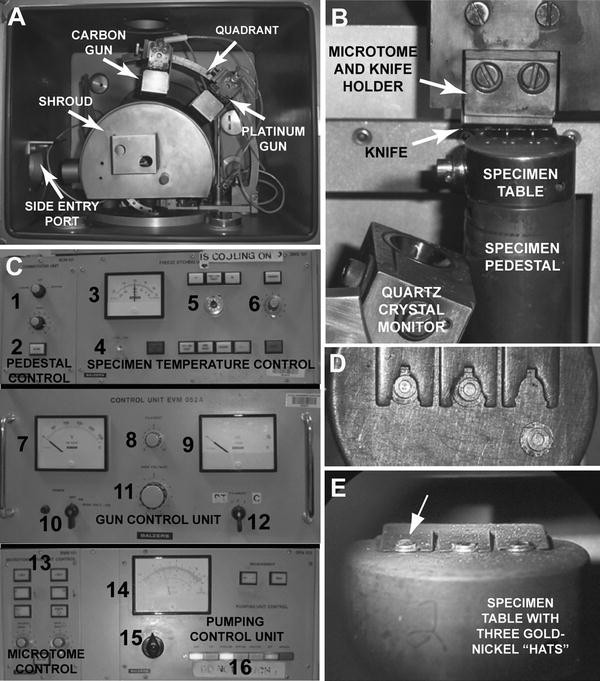
Controls and vacuum chamber components within the BAF 400D. (a) Vacuum chamber interior showing the electron beam guns, the cold shroud covering the specimen pedestal and microtome, and the side entry port for loading specimens. (b) Detail of components within the shroud enclosure. (c) The three major control panels of the BAF 400D. The specimen temperature control panel (top) and the electron beam gun control panel (middle) are above the deck while the pumping control unit and microtome control unit (bottom) are below the deck. Numbered controls include (1) Specimen pedestal cooling/rotating status, (2) Pedestal cooling mains, (3) Pedestal temperature gauge, (4) Temperature gauge range switch, (5) Temperature adjust potentiometer, (6) Knife cooling controls, (7) High voltage gauge, (8) Filament current, (9) Filament current gauge, (10) High voltage mains switch, (11) High voltage adjust, (12) Gun selection switch, (13) Motorized microtome control panel, (14) vacuum gauge, (15) Pump/standby/vent switch, (16) Pumping system status display. (d) Top view of a specimen table at room temperature showing “top hat” specimen carriers and spring clamp retainer. (e) Chilled specimen table with clamped specimen carriers ready for fracture. (d) and (e) are reproduced from Chandler and Roberson [67]
-
2.
Turn the supply valve of the dry nitrogen tank on several turns. Be sure that the regulator output pressure gauge reads about 90 psi (4–7 bar) and regulator valve is fully open.
-
3.
Switch on the water chiller to cool the diffusion pump. This step is not required if the freeze fracture unit has a turbomolecular pump or cryopump. Turn on the main electrical supply to the BAF 400D by moving the red MAINS switch on the lowest panel from the 0 to the 1 position.
-
4.
Turn the pumping control switch from the OFF to PUMP (see Fig. 10c-15). The green status light indicating automatic operation must be lit (see Fig. 10c-16). The instrument will automatically sequence the pump starts and valving so that in roughly 30 min a working vacuum should be achieved (see Note 1).

3.1.2 Gun and Quartz Crystal Monitor (QCM) Maintenance
-
1.
Inspect the carbon and platinum electron guns to insure they are clean. Loose carbon flakes or platinum tracking can cause arcing when the guns are fired. The filament must be properly positioned with respect to the rod and well centered, not sprung or skewed. The rod to be evaporated must be centered within the filament and set to the proper height. Maintain a log book for verifying gun maintenance history. The carbon rod carrying the platinum slug should give at least 12 runs before switching ends and installing a new platinum slug. During multiple runs, the platinum/carbon rod should be centered or adjusted for height after every six runs. The rod in the carbon gun requires adjustment and cleaning after every second run (see Note 2).
-
2.
To adjust and clean the guns, vent the chamber (see Fig. 10c-15), unscrew the door clamp and open the chamber (see Note 3).
-
3.
The electron guns are mounted on a quadrant pivoted at its base at the right front of the chamber (see Fig. 10a). The platinum gun is normally mounted so that it fires at a 45° angle from horizontal, the carbon gun directly over the specimen at 90°. To remove the carbon gun, unhook its hot wire from the connector at the rear of the chamber and the common ground wire from the platinum gun. Swing the quadrant out and remove the gun assembly by loosening the knurled nut that holds the gun to the rail.
-
4.
Remove the back plate and baffle of the gun by undoing two screws (see Fig. 11a). Then carefully remove the filament cover (see Fig. 11b). Do not touch the filament. Clean the parts removed using Scotch Brite pads and a screwdriver (gently) to remove any flaking carbon (see Fig. 11c-2, 11). Inspect the insulators to be sure that they are not heavily coated and clean or replace as necessary. Use a can of compressed air to blow away the debris left from cleaning. Inspect the filament for signs of twisting, unequal spacing of the coils, breaks, or decentering with respect to the carbon rod. Replace the filament at least every 30 runs or more often if required. The new filament may be centered by using the appropriate centering tool, a rod that fits into the electrode chuck and through the coils of the filament, as the new filament is tightened in place (see Fig. 11c-8). To set the height of the carbon rod, loosen the knurled ring at the bottom of the gun (see Fig. 11b) and gently press on the ring to release the tension around the carbon rod. Remove the carbon rod and flatten the burned end by rubbing on emery paper. Replace the carbon rod and use the larger diameter metal rod (see Fig. 11c-10) to position the carbon rod at the correct height (see Fig. 11d). Tighten the locking ring and recheck the rod height.
Fig. 11 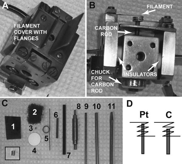
Electron beam guns. (a) Gun assembly with top shroud and aperture removed to reveal the filament cover with flanges. (b) Side view of gun assembly with filament cover removed to show rod and filament. (c) Tools needed for servicing the electron beam guns. Numbered items include (1) Emery paper. (2) “Scotch-Brite” scouring pad. (3) Platinum slug for platinum/carbon evaporation (an enlarged view is shown in the inset). (4) Quartz crystal. (5) Filament. (6) Two millimeter diameter carbon rod with recessed ends for platinum slug placement. (7) Three millimeter diameter carbon rod for carbon evaporation. (8) Filament centering jig. (9) Placement tool for platinum/carbon rod. (10) Placement tool for carbon rod. (11) Small screwdriver for gun assembly/disassembly. (d) Diagram showing correct placement of platinum/carbon and carbon rods within filament coils
-
5.
Replace the carbon gun in the 90° position on the quadrant taking care to line up the gun with the corresponding opening in the cooling shroud (see Fig. 10a). Reconnect the hot and ground wires. Record what you have done in the log book.
-
6.
To service the platinum gun, remove and clean as detailed for the carbon gun. The height of the platinum rod must be adjusted at least every 6 runs and after 12 runs, the platinum slug must be renewed. The carbon rods for this gun have recesses at each end that hold the slug (see Fig. 11c-6). The walls of the recess are fragile. The platinum slug (see Fig. 11c-3 and inset) often needs to be crimped end to end with a pair of pliers (be conservative—over crimping will result in a useless slug) to allow it to fit snugly without falling out. Reinstall the platinum gun at a 45° angle or at the appropriate angle for the procedure you are undertaking and reconnect the electrical leads. Be careful that the slot aperture in the cooling shroud lines up with the gun apertures (see Fig. 10a).
-
7.
The quartz crystal monitor (QCM) head is located inside the front of the cooling shroud or positioned on a separate stanchion near the pedestal (see Fig. 10b). To replace the quartz crystal, raise the shroud and loosen the clamping screw and slide the sensor out. The crystal is held in place by a spring-loaded bayonet ring; push in, twist and remove the locking ring, tip the old crystal out, and replace with a new one. Replace the locking ring and put the head back in the location block and secure. The QCM head is now adjusted to 60° from horizontal to best record depositions from both guns. Usually, it is reasonable to expect 30 or more normal runs per crystal.
-
8.
Replace the knife if damaged or dull. One can use thin, heavy duty, single-edged razor blades sold by most scientific supply houses that will last 2–4 runs or built to purpose knives that are much more expensive but will last up to 10–20 runs. Knives are replaced by loosening the screws on the front flange of the knife holder, extracting the old knife and sliding the new knife in place. As one tightens the screws, a fine tweezers is used to carefully align the knife edge with the surface of a pedestal-mounted specimen table such that it is equidistant along all parts of the knife edge.
-
9.
Check to see that the specimen pedestal (see Fig. 10b) has its open slot side facing to the left at the proper angle to receive the specimen table through the side entry counterflow loading port (see Fig. 10a). It may be rotated by turning on the commutator control mains (see Fig. 10c-1, 2), selecting ROTATE, and adjusting the speed to align the slot. Return the commutator controls to their original positions and replace the cooling shroud to operational position. Check to see that the counterflow loading port is closed and that the main door seating surface is free of foreign material which might cause a leak. Close the door and maintain firm pressure while moving the pumping module control switch (see Fig. 10c-15) from STANDBY to PUMP to repump the chamber.
-
10.
Once the chamber is repumped to a vacuum of about 10−4 mbar, the new platinum slug must be premelted to fuse it with the carbon surround and the carbon gun degassed. To premelt the platinum slug, set the voltage at 1,300 V (see Fig. 10c-10, 11), bring the current up slowly to 60 mA (see Fig. 10c-8), then shut down. To degas the carbon gun, set the voltage at 1,000 V, bring the current just off 0, and hold for 30 s (see Note 4).

3.1.3 Chemically Fixing and Freezing the Specimen
-
1.
The specimen, either isolated cells, or tissue cut into 1 mm3 cubes by razor blade, is chemically fixed by immersion in buffered glutaraldehyde, typically 2–4 % v/v for 1–2 h at room temperature. The fixative buffer should match that used for physiological experiments in osmolarity, ion composition and pH, although use of phosphate- or Hepes-buffers is preferred. Typically a buffer twofold in strength is diluted 1:1 with 4 % EM grade glutaraldehyde to prepare the fixative (see Note 5). Note that all chemical fixation should be carried out in a chemical hood in closed specimen containers using personal protective clothing including gloves and face/eye protection. One must avoid inhalation or skin contact and must use and dispose of as a hazardous material according to your institution’s environmental safety policies.
-
2.
Wash the tissue in three rinses of buffer, for 10 min each, to remove all fixative. Specimens of isolated cells may at this point be embedded in 1 % agar and sliced into cubes for ease of handling if desired. Alternatively, isolated cells can be centrifuged and resuspended to change solutions.
-
3.
Incubate specimens in 25–30 % v/v glycerol in distilled water for 30–60 min.
-
4.
Place the plunge freezing apparatus in an operating chemical fume hood and prepare by filling the Dewar reservoir with liquid nitrogen. Insert the metal well in which propane will be liquefied. When cold, deliver propane gas from a canister equipped with a controlled flow delivery spout. Place the spout at the bottom of the well and slowly turn on the flow of propane gas; once a puddle of liquid propane has formed, the flow of gas may be increased to fill the well with liquid propane (see Note 6). Note that propane–air mixtures are highly explosive; care must be taken to use a functioning chemical hood certified for use with explosive gases and in accordance with your institution’s environmental safety policy. One must ensure that there are no electrical sparks or open flames in the vicinity. In addition, note that all liquid cryogens (including liquid hydrocarbons, liquid nitrogen and liquid helium) present the potential hazard of frostbite should they come in contact with your body. Likewise they boil to form gases that have the potential to suffocate you in a poorly ventilated room. Always work in a well-ventilated area when using these cryogens.
-
5.
Line up several gold–nickel alloy “top hat”-shaped specimen carriers using fine, curved tweezers for hat manipulation. Place a glycerinated tissue cube in each hat or use a micropipette with cut off tip to deliver a drop of concentrated cell pellet into the well of the hat. Wick off any excess buffer using a filter paper wedge. Be sure that no buffer is present on the brim (flange) of the hat; buffer here may prevent mounting of the specimen on to the specimen table after freezing. This manipulation may require use of a dissecting microscope.
-
6.
Pick up each hat with curved tweezers and plunge into the liquid propane filled well with a single thrust and then some modest agitation. After immersion in the cryogen for 5 s, transfer the specimen to a storage basket within a small liquid nitrogen Dewar (see Fig. 12e). After freezing a number of specimens in this manner, one may either place them in containers for storage in a liquid nitrogen Dewar or mount them on a specimen table to be immediately used for freeze fracture.
Fig. 12 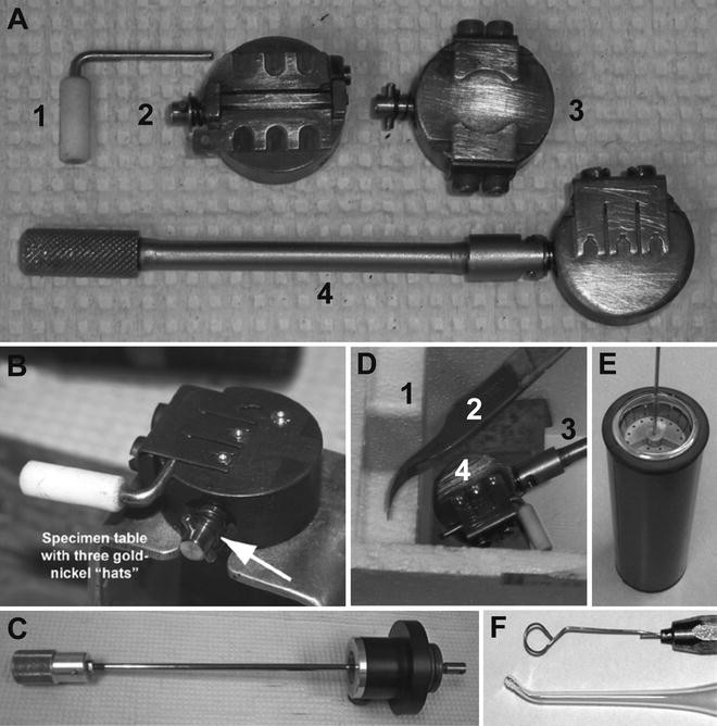
Specimen tables and tools for mounting specimens. (a) Multiple types of specimen tables are available. (1) “L” tool for opening and closing spring clamps on specimen tables. (2) A “complementary replica” specimen table in the open position; this table accepts specimens sandwiched between two hats. After mounting of specimens in the closed position, its book-like action can be opened thereby fracturing the specimens; both fractured faces of the specimen can then be replicated. (3) Custom specimen table with two spring clamps that hold specimen disks used in cold metal block freezing. (4) Standard three-slot specimen table attached to the short manipulator rod. (b) The standard specimen table with spring clamp opening tool. The cam-linked locking mechanism (arrow) can be actuated by either the short manipulator rod or the longer counterflow side entry loader rod in c. The table is shown locked down on a metal bracket for cleaning. (c) Counter-flow loading manipulator rod used for specimen table entry into the chamber. (d) Tools used for mounting standard specimen hats in the table while under liquid nitrogen: (1) Styrofoam enclosure for liquid nitrogen. (2) Fine curved tweezers for transferring specimen hats. (3) Short manipulator rod used for locking down specimen table to metal stand during specimen mounting. (4) Specimen table. (e) Specimen basket in liquid nitrogen Dewar for temporary storage of specimens. (f) Tools used for moving replicas from bath to bath during cleaning include a wire loop or a Pasteur pipette with a fire-polished tip. (b) and (f) are reproduced from Chandler and Roberson [67]

3.1.4 Mounting the Specimens
-
1.
Prior to mounting the frozen hats in a specimen table and with the freeze fracture unit at vacuum, begin cooling the rotary specimen pedestal in the chamber (see Fig. 10c-1, 2).
-
2.
Using the short specimen table manipulator, pick up an appropriate brass specimen table (see Fig. 12a-4) and insert it into the metal slot in the table top specimen stand (see Fig. 12b). Note that pushing the manipulator in and rotating clockwise locks the specimen table to the stand. Pushing in and rotating part way will allow the removal of the manipulator without unlocking the specimen table from the stand bracket. Pushing in and rotating the manipulator counter-clockwise as far as possible unlocks the specimen table from the stand while maintaining the grip of the manipulator on the table. Both the small manipulator and the larger counterflow loading device (see Fig. 12c) work identically. If you are not familiar with this feature, practice these maneuvers until they become natural.
-
3.
Pick an L-shaped key with a white nylon handle (see Fig. 12a-1) and place it in the groove beneath the spring clamp of the table. Rotate the key 90° to lift the clamp a small distance. Be sure that the specimen table is dry as ice will cause problems when loading hats. A hair dryer may be used to insure dryness. Standard “top hat” brass specimen carriers should easily slide under the raised spring clamp as shown in Fig. 10d.
-
4.
Place a metal retaining bracket in the custom Styrofoam container and fill the container with liquid nitrogen (see Fig. 12d). Using the small manipulator, move the specimen table from the table stand to the metal retaining bracket which is submerged in liquid nitrogen. Adjust the level of liquid nitrogen so that the whole table is submerged. Using a fine tweezers remove specimen-loaded hats from the Dewar storage basket (see Fig. 12e) one at a time and quickly move them onto the table, again fully submerged. Gently push each hat into the appropriate slot in the spring clamp. When all the support positions are full, top up the liquid nitrogen, rotate the key to lock the spring clamp over the hats and remove the key. Set the container aside until it is time to load the chamber and check frequently that the entire table and specimens are submerged in liquid nitrogen (see Note 7).
3.1.5 Cooling the Knife and Specimen Pedestal
-
1.
Open the liquid nitrogen Dewar valve marked LIQUID two turns. Actuate cooling valves leading to the specimen pedestal at the specimen temperature control module BMS 101. Set the temperature adjust potentiometer (see Fig. 10c-5) to 0, depress the TEMP ADJUST TABLE button and place the temperature read out range switch (see Fig. 10c-4) in the −170° to +50° position. Moving to the pedestal control unit BCM 101 on the left depress the MAINS switch (see Fig. 10c-2) and set the selector (see Fig. 10c-1) to the COOLING position. You should hear liquid nitrogen flowing into the instrument. Since pedestal cooling takes 5–10 min, some operators prefer to start the cooling process before mounting specimens on a table as described in the previous section. When the table has reached −170 °C, turn on the COOLING KNIFE button (see Fig. 10c-6).
3.1.6 Loading Specimens
-
1.
Vent the cooled chamber only after specimen-loaded hats have been mounted on a specimen table under liquid nitrogen as described in Subheading 3.1.4. Check to be sure that the liquid nitrogen Dewar VENT valve is open 1/4 turn. Change the vacuum control switch (see Fig. 10c-15) from PUMP to STANDBY and then to VENT after a few seconds. A distinct click should be heard as the venting valve opens. The pumping control should remain on VENT during specimen loading to prevent frost buildup in the chamber.
-
2.
Be sure the slot on the specimen pedestal is aligned to receive the specimen table and that the microtome arm is out of the way of table entry (see Fig. 10b).
-
3.
Pick up the submerged specimen table using the counterflow loading device (see Fig. 12c) and the same engagement protocol as was used for the short table manipulator (seeSubheading 3.1.4, step 2) After unlocking, slide the engaged specimen table free of the metal bracket and move the black collar of the counter flow loader as close as possible to the engaged specimen table. Swing the loading port open and insert the black collar into the port being careful to mate the locating pin. Smoothly guide the specimen table into the chamber and onto the specimen pedestal making sure the locking cam on the underside of the table is properly slid into the pedestal slot. You may watch the loading progress through the microscope. Lock the specimen table to the pedestal, disengage the loading rod from the table, retract the rod fully and then remove the loader assembly completely from the port. Close and hold the port cover and move the pumping control from VENT to PUMP. View your specimens through the microscope mount; they should appear as in Fig. 10e.
-
4.
As the vacuum recovers, adjust the rotary table temperature to −110 °C by turning the potentiometer (see Fig. 10c-5) on the freeze etch control unit to about 450 in steps of about 50 units until the table is at a steady −110 °C (see Note 1). When appropriate, change the temperature readout gauge to the −120° to −80° range (see Fig. 10c-4). As the table temperature is adjusted, you may degas the carbon gun by switching the gun control mains (see Fig. 10c-10) to ON, turning the filament setting (see Fig. 10c-12) to “C” and bringing the high voltage to 1,000 V (see Fig. 10c-7, 11). Turn up filament current (see Fig. 10c-8, 9) until the meter needle just lifts off zero. Hold this reading for 30 s (the gun filament should glow dimly), then turn all gun controls OFF (see Note 3).
3.1.7 Fracturing and Etching
-
1.
Turn the microtome mains (see Fig. 10c-13) to ON. To adjust the height of the knife, depress the appropriate advance button. When the knife temperature stabilizes as indicated by the ARM VALVE light going off and when the chamber vacuum has reached 2 × 10⁻⁶ mbar or better, fracturing may begin.
-
2.
Cut manually by rotating the knife control (left side of the instrument kneehole) clockwise in a smooth, steady motion. On each cycle, first advance the knife down by pushing the rotation button (Fig. 10c-13) long enough to move the knife in a 60° arc. This should lower the knife about 10 μm providing the advance speed and knife speed dials are both set on 2. Complete each knife cycle and do the actual cutting manually. A good cut is accompanied by a spray of fine ice chips from the specimen surface. When all specimens present a wide, evenly fractured surface, prepare to fire the guns (see Note 8).
3.1.8 Replica Formation
-
1.
Just before the final cut, switch the gun control module power on as before. Turn the selector switch to Pt and the high voltage to 2,100. Turn the quartz crystal monitor power ON, set the QCM range to the black 1× position and adjust the meter to zero with the audio ON. You are now ready to make the final cut. Etching proceeds from the time the knife clears the specimen until platinum is deposited. You must move quickly and carefully to prevent overetching. Fifteen seconds at −110 °C is suggested as a starting point but both specimen temperature and etching time must be empirically determined for your particular needs. The actual etching should be done with the knife positioned above the specimen table to provide a cold surface for sublimated water vapor to settle on, preventing redeposition of contaminants on the specimens.
-
2.
At the end of the etch period, park the knife at the left rear of its path, well out of the way of the gun apertures. Turn the filament current control (Fig. 10c-8) rapidly and smoothly until the emission current readout indicates 80 mA. The QCM audio will rise in pitch as platinum is deposited. Just as the QCM meter reads 2 on the top scale, turn the filament current to zero and switch the gun selector to the C position without reducing the voltage. Quickly note the QCM reading since there will be some overshoot and immediately adjust the high voltage to 2,500 V (Fig. 10c-7, 11). Smoothly turn up the filament current to 110 mA (Fig. 10c-8, 9). The voltage reading will drop to about 2,000 V. When the QCM reading has increased by seven small increments over the final platinum reading, turn the filament current to zero, the high voltage to zero, the gun selector to zero and turn the power to the gun control module OFF. Turn the QCM OFF, the temperature adjust OFF, and switch the temperature range switch to the lower, wide scale position. The QCM reading after platinum deposition should be 23–24 and after carbon deposition is complete 35–38; i.e., platinum reading plus 12 (see Notes 9–10).
At the end of the etch period, park the knife at the left rear of its path, well out of the way of the gun apertures. Turn the filament current control (Fig. 10c-8) rapidly and smoothly until the emission current readout indicates 80 mA. The QCM audio will rise in pitch as platinum is deposited. Just as the QCM meter reads 2 on the top scale, turn the filament current to zero and switch the gun selector to the C position without reducing the voltage. Quickly note the QCM reading since there will be some overshoot and immediately adjust the high voltage to 2,500 V (Fig. 10c-7, 11). Smoothly turn up the filament current to 110 mA (Fig. 10c-8, 9). The voltage reading will drop to about 2,000 V. When the QCM reading has increased by seven small increments over the final platinum reading, turn the filament current to zero, the high voltage to zero, the gun selector to zero and turn the power to the gun control module OFF. Turn the QCM OFF, the temperature adjust OFF, and switch the temperature range switch to the lower, wide scale position. The QCM reading after platinum deposition should be 23–24 and after carbon deposition is complete 35–38; i.e., platinum reading plus 12 (see Notes 9–10).
3.1.9 Retrieving and Cleaning Replicas
-
1.
Prepare space on the bench to deal with your replicas. To retrieve your specimens, vent the chamber as before. Using the counterflow loading device as before, slide the rod into the chamber, engage and unlock the table and slide the table off of the pedestal up to the collar and remove the device from the port.
-
2.
Slide the specimen table onto the metal retaining bracket of the table stand (Fig. 12b) and release the loader while locking the table to the stand. Free the hats from the specimen table using a key to raise the spring clamp and a fine point forceps to manipulate the hats.
-
3.
Set up a small Petri plate with purified water and a second Petri plate with sodium hypochlorite, 5–8 % or full strength laundry bleach (see Note 12). Carefully float each replica off its hat onto the surface of the water and allow it to sit for a few minutes. Then, using either a tool made of a fire polished Pasteur pipette or a wire loop (Fig. 12f), transfer each replica onto the surface of the bleach. Sodium hypochlorite will dissolve most tissue within 3–4 h although some tissues require an even longer period to be completely removed from the replicas (see Note 13).
-
4.
Next, rinse the replicas three times (10 min each) by floating on distilled water. Pick up the finished product with copper grids as one would pick up sections from the boat of a knife in ultramicrotomy. Grids with replicas are quite stable and may be stored indefinitely in clean grid boxes.
3.2 Quick Freezing, Deep Etching, and Rotary Shadowing
3.2.1 Preparing Specimen Carriers and Tissue Cushions for Cold Metal Block Freezing Using a “CryoPress”-Type Machine
-
1.
Specimen carriers are best prepared a day or 2 before use. Cut tabs off of aluminum disks unless they are to be used in attaching the carrier to the specimen head of the freezing machine. Line up a series of disks and to each one glue a centered 5 mm filter paper square using a single drop of 5 min epoxy resin. Cover the line of disks with Parafilm and press each one firmly until glue spreads out evenly. The top surface of the filter paper should remain glue-free. Let dry for 1 or 2 h.
-
2.
Remove Parafilm. On the opposite edges of each disk place two small drops of cyanoacrylate glue, then use forceps to carefully place a plastic ring on each aluminum disk perfectly centered. After preparing a row of five to ten carrier disks, place a metal weight that presses rings and disks together while the glue dries. Let the glue dry for several hours (see Note 14).
-
3.
If using fixed tissue as a cushion under the specimen to be frozen, rat liver should be fixed in formalin overnight, embedded in 1 % agar on a balsa wood disk, chilled at 4 °C until gelled, then sliced to 1 mm thick sections using a razor blade microtome. Wash slices in distilled water three times to remove fixative and store in the refrigerator until use. On the day of freezing, cut the slices into 5 mm square cushions with a razor blade and blot on a piece of filter paper.
3.2.2 Preparation of the CryoPress Cold Metal Block Freezer
-
1.
Place the liquid helium Dewar (Fig. 13a-4) under the custom high top table for the CryoPress, and insert the straight, double-walled transfer line through the cut out in the table and into the Dewar slowly as helium boils off. Bolt the flange of the transfer line (Fig. 13a-3) to the table. Lower the freezing machine onto the transfer line, carefully lining up the block chamber entrance with the transfer line tip. Insert the thermocouple into the block chamber housing (Fig. 13a-2) and connect to a voltmeter. Connect tubing to the helium Dewar relief valve (Fig. 13a-5) with the opposite end immersed in a beaker of water for pressurization. The tubing should have a “Y” junction, one branch in water, the other closed off by a pinchclamp for quick release of pressure.
Fig. 13 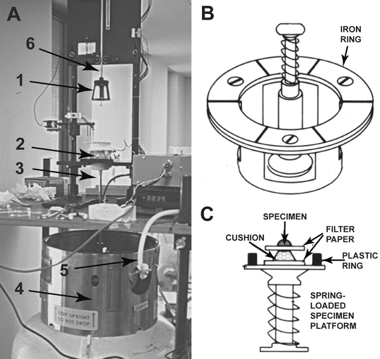
A CryoPress-type cold metal block freezing machine. (a) The freezing machine showing (1) The bayonet-mounted freezing head on which the specimen is placed. (2) The metal block enclosure with retractable shutter. (3) The double-walled transfer line used to bring liquid helium from the Dewar into the block enclosure. (4) A Dewar used to ship and store liquid helium. (5) Dewar relief valve tubing for pressurization. (6) Drop axle on roller bearings that guides the freezing head to the block enclosure. (b) Diagram of the freezing head. The head contains a spring-loaded specimen platform centrally positioned within an iron ring that is caught by an electromagnet so as to prevent bouncing of the head during specimen delivery to the liquid helium cooled copper block. (c) Detail of the specimen disk mounted on the freezing head platform. The cushion material can be sliced liver or lung tissue, a mound of cryo-sectioning gel, or foam rubber. The specimen may be either a strip of tissue or a dense cell suspension. (a) is reproduced from Chandler and Roberson [67]; (b) and (c) are reprinted from Merkle and Chandler [68], with the permission from Elsevier
-
2.
Clean the copper block by rubbing gently with Wenol on a soft cotton cloth; wipe the excess off, then clean the block by placing it in a beaker of ethanol and sonicating. Repeat with acetone. Remove block with forceps and wipe dry with tissue wipes being careful not to touch the block with your fingers. The solvents used for cleaning should be disposed of as determined by your institution’s environmental safety policies.
-
3.
Turn the pre-prepared specimen carrier disks upside down, number each with a lead pencil, and place a small square of double stick tape on their underside.

3.2.3 Preparation, Mounting and Freezing of Specimens
-
1.
Tissue specimens to be rapidly frozen while live must be carefully dissected to reveal the cellular layers to be studied since the depth of good freezing is limited to the most superficial 20 μm. Live tissues should be kept in physiological buffer until freezing to preserve normal structure. However, since most buffers contain salt, live specimens typically are used for freeze fracture without deep etching. Specimens to be fractured and deeply etched are usually chemically fixed first in glutaraldehyde as described in Subheading 3.1.3, step 1. They are then rinsed in distilled water several times and (as an option) are soaked in 15 % methanol for 10 s immediately before rapid freezing. The methanol acts as a cryoprotectant; specimens to be deep etched are never exposed to glycerol.
-
2.
At the beginning of each run, press the specimen platform of the freezing head (see Fig. 13a-1, b) onto the sticky underside of a specimen carrier and return to an upright position. Apply cushioning material to the specimen carrier disk. The cushion may be a slice of rat liver or alternatively a small mound of cryo-sectioning embedding gel. The specimen is then applied either to the rat liver directly or to a small square of filter paper sitting on top of the cryo-sectioning gel. Your specimen mounted disk should appear as in Fig. 13c.
-
3.
Close off the helium Dewar vent and begin pressurization to expel helium gas and then liquid helium into the block chamber and out under the retractable shutter covering the chamber. Wick off any remaining buffer from the edge of the specimen using filter paper, invert the freezing head with specimen and mount, bayonet style, onto the drop axle (see Fig. 13a-6). When the thermocouple voltage has leveled out and strong plumes of helium are being ejected, turn on the electromagnet anti-bounce mechanism; then activate the solenoid that allows the freezing head to drop by gravity toward the block chamber. During its free-fall, the chamber shutter is retracted and the specimen makes immediate contact with the cold metal block.
-
4.
The pressure on the helium Dewar is released, the electromagnetic anti-bounce mechanism turned off, the freezing head dismounted from the drop axle, and the specimen and freezing head platform immersed in a bath of liquid nitrogen. The specimen carrier disk is removed from the head by tweezers and placed in a separate liquid nitrogen container for temporary storage.
-
5.
The freezing head is warmed to room temperature using a hair dryer. The copper block is removed with custom pliers, warmed using a hair dryer, then cleaned by sonication with alcohol and acetone as described above.
-
6.
Steps 2–5 are repeated for each specimen.
3.2.4 Fracturing and Etching of Quick-Frozen Specimens
-
1.
The freeze fracture unit is set up and prepared for use as described in Subheading 3.1.2 with the exception that the platinum gun is positioned at 25° and the carbon gun is positioned at 70°–80°. As described in Subheading 3.1.4, the machine is pumped down and the specimen table pedestal precooled before specimen mounting.
-
2.
A custom-made specimen table is used that has two C-shaped spring flanges that clamp down both sides of the specimen carrier disk (see Fig. 12a-3). The specimen table is submerged in liquid nitrogen within the styrofoam chamber as shown in Fig. 12d with the flanges released. The quick frozen specimen is transferred into the bath and the plastic ring pried off of the disk using a second pair of fine tweezers; the disk is then slid under the flanges and clamped down.
-
3.
The freeze fracture unit is brought to atmospheric pressure and the mounted specimen table is locked down inside the chamber as previously described (see Subheading 3.1.6, steps 1–3). The fracturing and replication takes place as described for standard specimens with the following exceptions. First, prior to specimen fracture, the specimen pedestal must be set at a temperature compatible with etching. The temperature will likely range from −100 to −80 °C depending on the depth of etching desired (see Subheading 1.2.3). Second, great care must be taken in cutting the specimen. The knife must be perfectly level as determined prior to the run and approach of the knife to the specimen must be delicate but deliberate since only one or two shallow cuts of the specimen surface are allowed. Anything deeper will cut into the poorly frozen region of the specimen not too far below its surface (see Note 8). This means that the electron beam guns need to be set up for firing before the specimen is fractured. Third, once the specimen is fractured, the knife must be parked above the specimen during etching. The etching period will range from 1 to 10 min depending on the depth of etching required (see Subheading 1.2.3). Fourth, prior to shadowing, the specimen pedestal commutator button (Fig. 10c-1) is turned to ROTATE, its speed having been previously adjusted to about 3 Hz. The knife is then parked out of the way and the electron beam guns fired as described for standard specimens.
-
4.
Removal of the specimen and its cleaning and mounting on a grid is standard.
4 Notes
-
1.
The control and read out systems on the Leica EM BAF 060 have been completely converted from analogue to digital. All controls for lock and chamber pumping, specimen and knife temperature control, and gun and specimen positioning are now push button with LED readouts.
-
2.
Carbon or platinum evaporation can be tested by clamping a piece of filter paper on the specimen table, which when coated will show the distribution of material deposition. The area of deposition should be adequate to cover the specimen table and the quartz crystal monitor.
-
3.
In the Leica EM BAF 060 and JEOL JFD II, gun maintenance can be achieved without opening the front door of the vacuum chamber. Rather, the refurbished guns are mounted inside the gun lock, the lock pumped to vacuum, the entry to main chamber opened and the gun installed by motorized control to the proper angle. The Leica EM BAF 060 unit uses the newer EK 030 model electron beam gun while the Balzers BAF 400D uses the older EK 552 model guns. The EK030 guns are designed for automated use.
-
4.
If the platinum slug is not premelted there is danger that the slug will be shot ballistically at the specimen when the gun is first fired. If the carbon gun is not degassed, arcing is much more likely upon firing.
-
5.
Some investigators claim that high glutaraldehyde concentrations during fixation can lead to increased incidence of cross fractures—fractures that split through ice rather than following the membrane interior. For this reason combinations of glutaraldehyde and formaldehyde, such as Karnovsky’s fixative [66] are frequently used. We have not experienced such problems with 2 % glutaraldehyde. Use of osmium tetroxide, however, will prevent membrane fracturing and is to be avoided.
-
6.
Although we utilize plunge freezing with liquid propane in this protocol, use of a nitrogen slush for freezing cryoprotected specimens is common and possibly preferable in that the danger of explosion is avoided. Of even greater convenience would be use of new commercial refrigerants that replace Freon 12. Research on use of new refrigerants for standard freeze fracture protocols is sorely needed.
-
7.
In the Leica EM BAF 060 system, the fragile Styrofoam containers for specimen loading have been replaced by metallic loading chambers that accept specimen tables with a redesigned lockdown system.
-
8.
The knife should not actually cut the specimen but rather chip the ice away to allow splitting along natural fracture planes, i.e., the interior of membranes. Bona fide cutting of the specimen with the knife edge leads to knife marks and the crushing of biological structures. In addition, a dull knife leads to increased cutting and specimen damage as well as deeper knife marks due to burrs in the knife edge.
-
9.
The thickness of the carbon deposited during replication is critical to the integrity of the replica. Too much, and the replica will roll up like a window shade during cleaning never to be unrolled. Too little carbon and the replica will break up into thousands of irretrievable pieces. Differences in platinum thickness do not endanger replica integrity but will affect imaging in the microscope. Too much platinum and the fine structural details will be obliterated. Too little platinum and there will be inadequate contrast to visualize membrane topology.
-
10.
Arcing in the carbon gun happens fairly frequently triggering automatic turn off of the high voltage supply. Frequently, one can resume carbon deposition after arcing by a second round of turning on and adjusting the high voltage followed by more slowly increasing filament current.
-
11.
In the Leica EM BAF 060, the firing of both platinum and carbon guns is completely automated. Once initiated the high voltage and filament current of each gun is actuated in sequence by machine driven protocols. The ending of each evaporation period is accomplished by quartz crystal monitor control of shutters followed by automatic turn off of filament current and high voltage. This system aims to improve consistency in the thickness of platinum and carbon deposited which is critical as noted above.
-
12.
Tissues that can be difficult to dissolve, such as plant material, require longer periods of exposure to bleach, for example overnight. After 8 h of bleach, however, the replica becomes increasingly fragile and susceptible to fragmenting. Chromic acid is an alternative to bleach for hard to digest materials. See ref. 22 for alternative replica cleaning protocols.
-
13.
Some prefer using porcelain spot plates rather than plastic petri dishes for cleaning replicas. While cheaper, spot plates with shallow depressions make the cleaning and transfer of replicas more difficult and breakup of the replica during separation from the hat more likely.
-
14.
Quality of the specimen disks is dependent on the gluing steps. Too much 5 min epoxy glue and the filter paper square in the center of the disk will become saturated with glue. Too much cyanoacrylate glue under the plastic ring will soak the filter paper square making the disk unusable. Also too much glue may make the ring impossible to remove before freeze fracture.
References
Williams RC, Wyckoff RWC (1944) The thickness of electron microscopic objects. J Appl Physiol 15:712–716
Williams RC, Wyckoff RWC (1964) Applications of metal shadow-casting to microscopy. J Appl Physiol 17:23–33
Williams RC, Wyckoff RW (1945) Electron shadow micrography of the tobacco mosaic virus protein. Science 101:594–596
Price WC, Williams RC, Wyckoff RW (1945) The electron micrography of crystalline plant viruses. Science 102:277–278
Chandler DE (1986) Rotary shadowing with platinum-carbon in biological electron microscopy: a review of methods and applications. J Electron Microsc Tech 3:305–335
Steere RL (1957) Electron microscopy of structural detail in frozen biological specimens. J Biophys Biochem Cytol 3:45–60
Steere RL (1989) Freeze-fracture: a personal history. J Electron Microsc Tech 13:159–164
Bullivant S, Ames A (1966) A simple freeze-fracture replication method for electron microscopy. J Cell Biol 29:435–447
Weinstein RS, Bullivant S (1967) The application of freeze cleaving technics to studies on red blood cell fine structure. Blood 29:780–789
Moor H, Muhlethaler K, Waldner H et al (1961) A new freezing-ultramicrotome. J Biophys Biochem Cytol 10:1–13
Moor H, Mühlethaler K (1963) Fine structure in frozen-etched yeast cells. J Cell Biol 17:609–628
Moor H (1966) Use of freeze-etching in the study of biological ultrastructure. Int Rev Exp Pathol 5:179–216
Moor H (1969) Freeze-etching. Int Rev Cytol 25:391–412
Newman TM (1995) A guide to equipment for production of freeze-fracture replicas. In: Severs NJ, Shotton DM (eds) Rapid freezing, freeze fracture and deep etching. Wiley-Liss Inc., New York, pp 51–67
Branton D (1966) Fracture faces of frozen membranes. Proc Natl Acad Sci U S A 55:1048–1056
Branton D (1967) Fracture faces of frozen myelin. Exp Cell Res 45:703–707
Pinto da Silva P, Branton D (1970) Membrane splitting in freeze-etching. Covalently bound ferritin as a membrane marker. J Cell Biol 45:598–605
Branton D, Bullivant S, Gilula NB et al (1975) Freeze-etching nomenclature. Science 190:54–56
Gilula NB, Branton D, Satir P (1970) The septate junction: a structural basis for intercellular coupling. Proc Natl Acad Sci U S A 67:213–220
Yu J, Branton D (1976) Reconstitution of intramembrane particles in recombinants of erythrocyte protein band 3 and lipid: effects of spectrin-actin association. Proc Natl Acad Sci U S A 73:3891–3895
Heuser J (2011) The origins and evolution of freeze-etch electron microscopy. J Electron Microsc (Tokyo) 60:S3–S29
Severs NJ (2007) Freeze fracture electron microscopy. Nat Protoc 2:547–576
McIntyre JA, Gilula NB, Karnovsky MJ (1974) Cryoprotectant-induced redistribution of intramembranous particles in mouse lymphocytes. J Cell Biol 60:192–203
Chandler DE, Heuser J (1979) Membrane fusion during secretion: cortical granule exocytosis in sea urchin eggs as studied by quick-freezing and freeze fracture. J Cell Biol 83:91–108
Dubochet J (2007) The physics of rapid cooling and its implications for cryoimmobilization of cells. Methods Cell Biol 79:7–21
Gilkey J, Staehelin LA (1986) Advances in ultrarapid freezing for the preservation of cellular ultrastructure. J Electron Microsc Tech 3:177–210
Heuser JE, Reese TS, Landis DM (1976) Preservation of synaptic structure by rapid freezing. Cold Spring Harb Symp Quant Biol 40:17–24
Walther P (2003) Recent progress in freeze-fracturing of high-pressure frozen samples. J Microsc 212:34–43
McDonald KL (2009) A review of high-pressure freezing preparation techniques for correlative light and electron microscopy of the same cells and tissues. J Microsc 235:273–281
Rash JE, Hudson CS (1979) Freeze-fracture. Methods artifacts and interpretation. Raven, New York
Abeysekera RM, Robards AW (1995) Freeze fracture artifacts: how to recognize and avoid them. In: Severs NJ, Shotton DM (eds) Rapid freezing, freeze fracture and deep etching. Wiley-Liss Inc., New York, pp 69–88
Heuser JE, Reese TS, Dennis MJ et al (1979) Synaptic vesicle exocytosis captured by quick freezing and correlated with quantal transmitter release. J Cell Biol 81:275–300
Chandler DE, Heuser J (1980) Arrest of membrane fusion events in mast cells by quick-freezing. J Cell Biol 86:666–674
Plattner H, Hentschel J (2006) Sub-second cellular dynamics: time-resolved electron microscopy and functional correlation. Int Rev Cytol 255:133–176
Chandler DE, Heuser J (1980) The vitelline layer of the sea urchin egg and its modification during fertilization: a freeze fracture study using quick freezing and deep etching. J Cell Biol 84:618–632
Larabell CA, Chandler DE (1988) The extracellular matrix of Xenopus laevis eggs: a quick-freeze, deep-etch analysis of its modification at fertilization. J Cell Biol 107:731–741
Larabell C, Chandler DE (1991) Fertilization-induced changes in the vitelline envelope of echinoderm and amphibian eggs: self assembly of an extracellular matrix. J Electron Microsc Tech 17:294–318
Hirokawa N, Heuser JE (1981) Quick-freeze, deep-etch visualization of the cytoskeleton beneath surface differentiations of intestinal epithelial cells. J Cell Biol 91:399–409
Hirokawa N (1986) Quick freeze, deep etch of the cytoskeleton. Methods Enzymol 134:598–612
Heuser J (2000) The production of ‘cell cortices’ for light and electron microscopy. Traffic 1:545–552
Nermut MV (1995) Manipulation of cell monolayers to reveal plasma membrane surfaces for freeze-drying and surface replication. In: Severs NJ, Shotton DM (eds) Rapid freezing, freeze fracture and deep etching. Wiley-Liss Inc., New York, pp 151–172
Heuser JE, Kirschner MW (1980) Filament organization revealed in platinum replicas of freeze-dried cytoskeletons. J Cell Biol 86:212–234
Heuser J (1980) Three-dimensional visualization of coated vesicle formation in fibroblasts. J Cell Biol 84:560–583
Hanson PI, Roth R, Lin Y et al (2008) Plasma membrane deformation by circular arrays of ESCRT-III protein filaments. J Cell Biol 180:389–402
Heuser JE (1983) Procedure for freeze-drying molecules adsorbed to mica flakes. J Mol Biol 169:155–195
Heuser J (1989) Protocol for 3-D visualization of molecules on mica via the quick freeze, deep etch technique. J Electron Microsc Tech 13:244–263
Szajner P, Weisberg AS, Lebowitz J et al (2005) External scaffold of spherical immature poxvirus particles is made of protein trimers, forming a honeycomb lattice. J Cell Biol 170:971–981
Matsuoka K, Schekman R, Orci L et al (2001) Surface structure of the COPII-coated vesicle. Proc Natl Acad Sci U S A 98:13705–13709
Takizawa T, Saito T (1996) Freeze fracture enzyme cytochemistry: application of enzyme cytochemistry to freeze-fracture cytochemistry. J Electron Microsc (Tokyo) 45:242–246
Elias PM, Goerke J, Friend DS et al (1978) Freeze-fracture identification of sterol-digitonin complexes in cell and liposome membranes. J Cell Biol 78:577–596
Elias PM, Friend DS, Goerke J (1979) Membrane sterol heterogeneity. Freeze-fracture detection with saponins and filipin. J Histochem Cytochem 27:1247–1260
Skepper JN (1989) Membrane segregation in atrioventricular nodal myocytes of the golden hamster (Mesocricetus auratus). A cytochemical study using filipin and tomatine. J Anat 163:143–154
Pinto da Silva P, Torrisi MR, Kachar B (1981) Freeze-fracture cytochemistry: localization of wheat-germ agglutinin and concanavalin A binding sites on freeze-fractured pancreatic cells. J Cell Biol 91:361–372
Pinto da Silva P, Parkison C, Dwyer N (1981) Fracture-label: cytochemistry of freeze-fracture faces in the erythrocyte membrane. Proc Natl Acad Sci U S A 78:343–347
Pinto da Silva P, Kan FWK (1984) Label-fracture: a method for high resolution labeling of cell surfaces. J Cell Biol 99:1156–1161
Pavan A, Mancini P, Cirone M et al (1989) Capping of HLA antigens in human lymphocytes as followed by immunogold label-fracture. J Histochem Cytochem 37:1489–1496
Andersson Forsman C, Pinto da Silva P (1988) Fracture-flip: new high-resolution images of cell surfaces after carbon stabilization of freeze-fractured membranes. J Cell Sci 90:531–541
Pavan A, Mancini P, Lucania G et al (1990) High-resolution surface views of human lymphocytes during capping of CD4 and HLA antigens as revealed by immunogold fracture-flip. J Cell Sci 96:151–157
Fujimoto K (1995) Freeze-fracture replica electron microscopy combined with SDS digestion for cytochemical labeling of integral membrane proteins—application to the immunogold labeling of intercellular junctional complexes. J Cell Sci 108:3443–3449
Fujimoto K (1997) SDS-digested freeze-fracture replica labeling electron microscopy to study the two-dimensional distribution of integral membrane proteins and phospholipids in biomembrane: practical procedure, interpretation and application. Histochem Cell Biol 107:87–96
Heuser JE (1980) Quick-freeze, deep-etch method of preparing samples for 3-D electron microscopy. Trends Biochem Sci 6:64–68
Heuser JE (1981) Preparing biological specimens for stereo microscopy by the quick-freeze, deep-etch, rotary-replication technique. Methods Cell Biol 22:97–122
Chandler DE, Kazilek CJ (1986) Extracellular coats on the surface of Strongylocentrotus purpuratus eggs: stereo electron microscopy of quick-frozen and deep-etched specimens. Cell Tissue Res 246:153–161
Morone N, Fujiwara T, Murase K et al (2006) Three-dimensional reconstruction of the membrane skeleton at the plasma membrane interface by electron tomography. J Cell Biol 174:851–862
Morone N, Nakada C, Umemura Y et al (2008) Three-dimensional molecular architecture of the plasma membrane associated cytoskeleton as reconstructed by freeze-etch electron tomography. Methods Cell Biol 88:207–236
Karnovsky MJ (1965) A formaldehyde-glutaraldehyde fixative of high osmolality for use in electron microscopy. J Cell Biol 27:137A–138A
Chandler DE, Roberson RW (2009) Bioimaging: current concepts in light and electron microscopy. Jones and Bartlett Learning, Burlington, MA
Merkle CJ, Chandler DE (1993) Visualization of exocytosis by quick freezing and freeze-fracture. Methods Enzymol 221:112–123
Severs NJ, Shotton DM (1995) Rapid freezing, freeze fracture, and deep etching. Wiley-Liss Inc., New York
Shotton DM (1998) Freeze fracture and freeze etching. In: Celis JE (ed) Cell biology: a laboratory handbook, vol 3. Academic, New York, pp 310–322
Severs NJ, Shotton DM (1998) Rapid freezing of biological specimens for freeze fracture and deep etching. In: Celis JE (ed) Cell biology: a laboratory handbook, vol 3. Academic, New York, pp 299–309
Heuser JE, Salpeter SR (1979) Organization of acetylcholine receptors in quick-frozen, deep-etched, and rotary-replicated Torpedo postsynaptic membrane. J Cell Biol 82:150–173
Hirokawa N (1989) Quick-freeze, deep-etch electron microscopy. J Electron Microsc (Tokyo) 38:S123–S128
Lupu F, Constantinescu E (1989) A new freeze-drying device for platinum replica studies of cell surface and cytoskeleton: an example using immunogold-labeled human erythrocytes. J Electron Microsc Tech 11:76–82
Severs NJ, Robenek H (2008) Freeze fracture cytochemistry. Methods Cell Biol 88:181–204
Severs NJ (1995) Freeze-fracture cytochemistry: an explanatory survey of methods. In: Severs NJ, Shotton DM (eds) Rapid freezing, freeze fracture and deep etching. Wiley-Liss Inc., New York, pp 173–208
Ciolofan C, Li XB, Olson C et al (2006) Association of connexin 36 and zona occludins-1 with zona occludins-2 and the transcription factor zona occudins-1-associated nucleic acid-binding protein at neuronal gap junctions in rodent retina. Neuroscience 140:433–451
Author information
Authors and Affiliations
Editor information
Editors and Affiliations
Rights and permissions
Copyright information
© 2014 Springer Science+Business Media, New York
About this protocol
Cite this protocol
Chandler, D.E., Sharp, W.P. (2014). Freeze Fracture and Freeze Etching. In: Kuo, J. (eds) Electron Microscopy. Methods in Molecular Biology, vol 1117. Humana Press, Totowa, NJ. https://doi.org/10.1007/978-1-62703-776-1_6
Download citation
DOI: https://doi.org/10.1007/978-1-62703-776-1_6
Published:
Publisher Name: Humana Press, Totowa, NJ
Print ISBN: 978-1-62703-775-4
Online ISBN: 978-1-62703-776-1
eBook Packages: Springer Protocols