
Abstract
In recent years, microfluidic devices have become widely used in biology, and with the advantage of requiring low sample volumes, enables previously technologically infeasible experiments in hematopoietic stem cell (HSC) research. Here, we introduce a microfluidic device to investigate dynamic interactions between HSC and model niches in vitro. The device comprises a pneumatic valve which enables the culturing of different types of niche cells in different parts of the same device. Single HSCs can then be injected into the microfluidic device, manipulated, and placed onto different niches within the same device as controlled by the user. Here, we describe the device fabrication method, the HSC collection methodology, and the operational procedure for the device.
Key words
1 Introduction
The first applications for microfluidics were focused on the capability of these devices to handle small amounts of liquids in the nanoliter and picoliter range and led to the advent of the current ink-jet technology [1]. In late 1990s, “soft lithography” techniques enabled microfluidic devices to be fabricated with the silicone elastomer polydimethylsiloxane (PDMS) [2], which brought forth the advantages of low cost, simple fabrication steps, and bio-compatibility. As such, microfluidics devices are now used in biology and biochemistry as a tool that leverage those capabilities and have enabled enumerable “lab-on-a-chip” applications. Indeed, almost 10,000 papers about microfluidics have been published in last 10 years alone [3].
Microfluidic devices are comprised of glass, thermal-plastic, or as mentioned above, PDMS. Glass or silicon wafer based microfluidics require processes to “etch” channels into the material and a thermal bonding process to seal the channels. Glass-based microfluidics can yield sophisticated three-dimensional structure, but cannot be reused. On the other hand, PDMS based microfluidics has relatively simple fabrication steps via soft-lithography, and the process yields a silicon master mold, in which large numbers of PDMS devices can be fabricated. PDMS is porous and flexible, enabling features such as pneumatic valves to be incorporated into the device [4].
More recently, researchers have used other materials to produce microfluidic device. Polystyrene microfluidics can be fabricated by the hot embossing technique [5]. As polystyrene is the same material as the tissue culture flasks, the familiar material properties may be advantageous for biologists. Like PDMS, polystyrene is also optically transparent, which enables live cell imaging. Recently, paper based microfluidics has been developed for disease diagnostic purpose [6]. Unlike the other types of the microfluidics, the paper based microfluidics leverages the wettability of the material. The small amount of liquid is absorbed and transferred by a highly wettabile material (unpatterned area), but it is blocked or guided by a low wettability material (patterned area with wax or photoresist).
Microfluidic devices are suitable for biology and biochemistry area with the advantages of low volume consumption of reagent and samples, and PDMS microfluidics has key properties—optical transparency, high gas permeability and biocompatibility—that enable them to be amenable for biological and biochemical research [7]. In addition, microfluidic components such as valves, mixers, pumps have been incorporated into those microfluidic systems. Beside the basic components, one can embed optical or electrical parts into a device for sensing or actuating. Finally, the small size of microfluidics enables control and manipulation of single cells, which we describe here.
Microfluidics has recently been utilized for hematopoietic stem cell research and techniques such as purifying, analyzing, or culturing. Wu et al. [8] introduces an integrated microfluidic system capable of sorting of HSCs from cord blood that sorting efficiency is as high as 88 %. The total sorting time of the device takes only 40 min which is much faster than with the traditional method. A filter embedded PDMS device has also been shown to purify HSCs from the bone marrow with an efficiency that is comparable with flow cytometry [9]. Furthermore, the micro-well array [10, 11], cell trapping [12, 13], or valved chamber structures [14] have all recently been adaptable to microfluidic devices that enable to single HSC analysis and manipulation under dynamic conditions.
Here, we describe a microfluidic device that enables investigating the dynamic interactions between HSCs and the niche microenvironments of the bone marrow in vitro. The device consists of three layers made of PDMS: the valve channel, the thin membrane, and the fluidic channel (Fig. 1a). The sandwiched PDMS membrane is flexible, so it can be deflected to the fluidic channel and blocking it depends on the pressure applied through the valve channel, pneumatically (Fig. 1b). A set of the valve channel A is utilized to seed and culture the different niches in the chambers. Once, valve channel B is actuated, the injected HSC is guided along the fluidic channel to expose it to the different niches.

A schematic of PDMS device and its operation process. (a) Top view (b) cross-sectional view of PDMS device. (c) Cell seeding process. The fluidic channels are separated by controlling the valve (the valve a: Closed, the valve b: Open). (d) Cell culture for 2 days until get confluence in an incubator. (e) Valve modification. The valve pressure is controlled to connect the fluidic channels each other (the valve a: Open, the valve b: Closed). (f) HSCs injecting and transporting. The injected HSC is transported by the pressure from the syringe placing over the height adjustable stage
2 Materials
2.1 Microfluidic Chip Fabrication Process Components
-
1.
Cleanroom facility (including spin coater, hotplate, and aligner).
-
2.
SU-8 photoresist and developer (Microchem, Newton, MA, USA).
-
3.
Silicon wafer (NOVA electronic materials, Flower Mound, TX, USA).
-
4.
Photomask.
-
5.
HMDS (Hexamethyldisilazane) (Sigma-Aldrich, St. Louis, MO, USA).
-
6.
Sylgard 184 (PDMS) (Dow Corning, Midland, MI, USA).
-
7.
Micro-punch (Syneo, West Palm Beach, FL, USA).
2.2 HUVEC Culturing and Seeding Components
-
1.
PBS.
-
2.
EGM-2 cell culture media (Lonza).
-
3.
Dextran from Leuconostoc spp. (Sigma-Aldrich, St. Louis, MO, USA).
-
4.
Fibronectin solution: 5 % fibronectin stock solution in PBS (final fibronectin concentration, 50 μg/ml).
-
5.
Syringe pump (Harvard Apparatus, Holliston, MA, USA).
-
6.
Blunt needle (VWR, Suwanee, GA, USA).
-
7.
Small tubing (30 gauge) (Cole-Parmer, Vernon Hills, IL, USA).
-
8.
Large tubing (14 gauge) (Cole-Parmer, Vernon Hills, IL, USA).
-
9.
Lab jack (Fisher Scientific, Pittsburgh, PA, USA).
2.3 HSC Component
-
1.
Sterile 100 × 15 mm polystyrene petri dishes.
-
2.
Sterile scissors to remove femur and tibias.
-
3.
Sterile 10 ml syringe, 21 G and 25 G needle to expel bone marrow from medullary cavities.
-
4.
BD Falcon cell strainer, 40 μm (#352340) and BD Falcon 5 ml polystyrene round-bottom tube with cell strainer cap (#352235).
-
5.
MACS Separation LS column (Miltenyi Biotec Inc, Auburn, CA).
-
6.
StemSep Magnet (STEMCELL Technologies Inc., Vancouver, BC, Canada) or Miltenyi AutoMACS Pro separator (Miltenyi Biotec Inc, Auburn, CA).
-
7.
Mouse Lineage Cell Depletion Kit (Miltenyi Biotec Inc, Auburn, CA).
-
8.
Blocking buffer: 5 % normal mouse serum in PBS.
-
9.
Washing and staining buffer: PBS supplemented with 2 % heat-inactivated fetal bovine serum.
-
10.
Monoclonal antibodies (eBioscience, San Diago, CA): lineage antibodies include Ly-6G (Gr1) ~ FITC (clone RB6-8C5), CD11b ~ FITC (clone M1/70), Ter119(Ly-76) ~ FITC (Clone TER119), CD45R(B220) ~ FITC (Clone RA3-6B2), CD8a ~ FITC (Clone 53-6.7) and CD4 (Clone GK1.5). CD150 ~ PE (Clone mShad150), Ly-6A/E (Sca-1) ~ PE-Cy7 (Clone D7), CD117 (c-Kit) ~ APC (Clone 2B8), and CD48 ~ pacific blue (clone HM48-1, Biolegend, San Diago, CA).
-
11.
BD FACS Aria II Cell Sorter (BD Biosciences, San Jose, CA).
3 Methods
3.1 SU-8 Master Mold Process (Fig. 2a–d)

Device fabrication process. A mold for PDMS device was fabricated by conventional photo-lithography process. (a) Spin coating of PR over a silicon wafer. (b) Exposing UV light through the photomask. (c) Developing the PR by immersing the UV exposed wafer. (d) Silanizing the developed wafer to prevent the PDMS adhesion during a curing process. (e) Pouring the mixed PDMS over a mold and cure. (f) Peeling off the cured PDMS. (g, h) Oxygen plasma bonding with another PDMS slab
This process should be done in the cleanroom facility with proper personal protective equipment. For the best results of the SU-8 process, the users should follow the specific protocols (spin coater speed, UV exposure dose, bake temperature and time, development time, etc.) that have been offered by the commercial supplier of the photoresist or the cleanroom administrator.
-
1.
Design photomask patterns using CAD software. The designed patterns can be transferred to the chrome photomask from commercial supplier.
-
2.
Clean the silicon wafer (see Note 1 ).
-
3.
Spin-coat the SU-8 2050 photoresist over the silicon wafer with the spin speed of 500 × g for 30 s to get the final film thickness to 50 μm.
-
4.
Pre-bake the spin-coated wafer over the hotplate set to 95 °C for 10 min (see Note 2 ).
-
5.
Exposure the UV light using aligner tool.
-
6.
Post-exposure bake the UV exposed wafer over the hotplate set to set to 95 °C for 8 min.
-
7.
Immerse the baked wafer into the developer and stir the developer gently until all the unexposed photoresist dissolve in the developer (~5 min).
-
8.
Wash the residue of the developer with IPA.
-
9.
Place the patterned master mold with petri-dish containing 1 ml of HDMS (Hexamethyldisilazane) in the desiccator. Connect the desiccator to the vacuum line of the fume hood, and then let HMDS to evaporate at least 1 h. During the process, the surface of the master mold is coated with HMDS vapor which prevents the cured PDMS from sticking over the master mold (see Note 3 ).
3.2 PDMS Fabrication Process (Fig. 2e–h)
-
1.
Mix the PDMS base and the PDMS curing agent thoroughly with 10:1 ratio by weight. Place the mixed PDMS in a vacuum desiccator until the air bubbles disappear.
-
2.
Pour the PDMS over the HMDS treated master mold. Place the PDMS poured master mold in the convection oven which temperature is set to 65 °C overnight.
-
3.
Using a knife or scalpel, cut out around the cured PDMS device and peel off the cured PDMS device from the master mold gently. Cut the PDMS slap into individual devices if necessary (see Note 4 ).
-
4.
Spin-coat (500 × g, 5 min) the PDMS mixture (10:1 ratio mixture) over the HMDS treated glass slide to make a thin PDMS membrane (~10 μm thickness). And cure the spin-coated glass slide over the 110 °C hotplate for 20 min.
-
5.
Expose the surface of the PDMS device (valve channel) and thin PDMS coated glass slide to oxygen plasma for 30 s using a plasma cleaner. Then, place the PDMS device (valve channel side) over the thin PDMS coated glass slide to bond each other.
-
6.
Place the bonded device over the 85 °C hotplate overnight to increase the bonding strength.
-
7.
Peel off the plasma bonded device from the slide glass.
-
8.
Punch the inlets and outlets of the PDMS devices with 0.75 mm diameter punch.
-
9.
Do the plasma bond the fluidic channel PDMS device with the PDMS membrane bonded device to make three PDMS layers (valve channel, membrane and fluidic channel).
3.3 Collect the HSC
3.3.1 Bone Marrow Harvesting
-
1.
Euthanize the mouse (see Note 5 ) and then wet the pelt thoroughly with 70 % ethanol.
-
2.
Strip skin from hind limbs, remove excess tissue; use sterile sharp scissors, cut off the legs at the hip joints, separate femurs and tibias at the knee joints.
-
3.
Flush the marrow using 21G (femurs) and 25G (tibias) needles attached to a syringe. Collect the bone marrow cells in PBS containing 2 % FBS.
-
4.
Make a single cell suspension using 21G needle and pass cells through 40 μM cell strainer to remove cell clumps.
-
5.
Count the cell number using hemocytometer after dilution in 2 % acetic acid (1:1) and Trypan blue (1:1) (see Note 6 ). Set aside about 5 million cells for control staining. Take the remaining cells for depletion of cells positive for lineage.
3.3.2 Magnetic Separation and Cell Sorting for HSC
-
1.
Isolation of lineage negative cells from bone marrow cells is carried out essentially as described in the protocol of Mouse Lineage Cell Depletion Kit (Miltenyi Biotec). After magnetic labeling, magnetic separation is performed with either LS column (Miltenyi Biotec) or Miltenyi AutoMACS Pro separator (Miltenyi Biotec).
-
2.
Count the enriched lineage negative fraction cells on a hemocytometer and pellet cells at 300 × g for 5 min at 4 °C. Resuspend cells into 100–200 μl of blocking buffer for 15–20 min at 4 °C. Then wash with >4 volume of washing buffer, mix, and pellet cells at 300 × g for 5 min at 4 °C.
-
3.
Prepare lineage-FITC antibody cocktail (Anti-Gr1, Mac1, B220, Ter119, CD4 and CD8) along with Anti-c-Kit-APC, Anti-Sca1-PE-Cy7, Anti-CD150-PE, Anti-CD48-Pacific blue in 100–200 μl staining buffer.
-
4.
Resuspend cell pellet in antibody cocktail and incubate at 4 °C for 15–20 min.
-
5.
Meanwhile set control staining with the bone marrow cells set aside. Use 0.5–1 million bone marrow cell per control staining. No stain control and single color staining control for each fluorochrome used (FITC, PE, APC, PE-CY7, Pacific Blue). Anti-B220 of each fluorochrome could be used for single color staining control.
-
6.
Add >4 volume of washing buffer, mix, and pellet cells at 300 × g for 5 min at 4 °C.
-
7.
Wash cells once more and resuspend cell pellet in 0.5–1.0 ml of washing buffer. Get single cell suspension by passing through cell-strainer cap on BD Falcon 5 ml polystyrene tube.
-
8.
Sort HSC with BD FACS Aria II Cell Sorter by gating on Lineage-c-Kit+Sca-1+CD150+CD48− (Fig. 3) (see Note 7 ).
Fig. 3 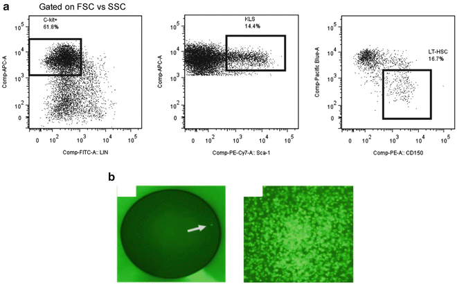
Gating scheme for sorting hematopoietic stem cells (HSC). (a) Each dot plot represents the events contained in the previous electronic gate. The percentage shown in each dot plot represents the fraction of events that fall within the indicated gate. The flow cytometry analysis program FlowJo 7.0 was used to generate the dot plots shown. (b) (Left ) Example of single GFP expressing HSC (arrow ) sorted into a single well of a plate for in vitro studies and (right ) a hematopoietic colony formed from a single HSC following 12 days of culture in semisolid medium
-
9.
Pellet the sorted HSC at 300 × g for 5 min at 4 °C. Resuspend into HSC culture medium (Iscove’s modified Dulbecco’s medium (IMDM), 15 % FBS (HyClone), 2 % penicillin/streptomycin B supplemented with 50 ng/ml recombinant murine stem cell factor, 20 ng/ml recombinant murine interleukin-3, 50 ng/ml recombinant human interleukin-6 (R&D system) and ready to culture HSC in microfluidic device (see Note 8 ).
-
10.
Direct cell sorting of single HSC into the wells of the microfluidic device can be achieved by using the automated cell deposition unit (ACDU) on the FACSAria. The ACDU allows cells to be deposited at specified locations in a pre-or self-defined plate format. The coordinates of the wells are programmed into the ACDU using standard procedures and a precise number of cells are deposited into each well. Of note, the software FACSDiva v8 on the FACSAria is capable of indexed cell sorting allowing for the identification of the phenotype of an individual single cell selected by the well in which it was deposited. Functional evaluation of HSC can be performed by sorting single cells into each well of a plate and following survival and growth for 3–5 days. Optimal conditions for this sort are using cells from a eGFP expressing mouse and sorting into a Terasaki plate that has 20 μl wells. When HSC are plated this way, we often achieve identification and differentiation of single cells in 90–95 % of wells.

3.4 Microfluidic Device Operation and Endothelial Cell Seeding
-
1.
Prepare three 1 ml syringes filled with PBS.
-
2.
Connect the smaller tubing (~1 m long) to the larger tubing (~2 cm long), which is connected to a syringe with a blunt needle.
-
3.
Load the syringes to the syringe pump and connect to the microfluidic chip (valve channel A, B).
-
4.
Operate the syringe pumps with the slow flow rate setup (~1 μl/min) until all the air pushed away in the valve channel through the PDMS membrane. Release the pressure after removing all the air from the valve channels (see Note 9 ).
-
5.
Inject the fibronectin solution (50 μg/ml) to the fluidic channel, and create a small (~100 μl) fibronectin droplet at the both inlet and outlet to ensure that the channel stays wet. And incubate the microfluidic chip in the temperature (37 °C), CO2 (5 %) and humidity (90 %) controlled incubator for 1 h.
-
6.
Operate the syringe pump which connected the valve channel A to add extra the PBS (~20 μl) into the valve channel A. Stop the syringe pump when the PDMS membrane is deflected and blocked the fluidic channel (Fig. 1c).
-
7.
Prepare 5,000,000 cells/ml of HUVECs in 100 μl of endothelial growth media (EGM-2) with 8 % dextran.
-
8.
Inject the prepared HUVECs using a pipette into the chambers through the inlet A and C (Fig. 1d).
-
9.
Incubate the HUVECs seeded device in an incubator for 1 h.
-
10.
Load three 10 ml syringe filled with EGM-2 at the syringe pump and connect the syringes to the microfluidic device through the inlet A to C.
-
11.
Perfuse EGM-2 into the device with the flow rate of 2 μl/min. A monolayer of endothelial cell is formed on the inside of the device within 2–3 days (Fig. 1d).
-
12.
Once HUVECs become confluent, release the pressure from the “valve A” by disconnecting the tubing from the device. Then, apply the pressure for the “valve B” by adding extra PBS (~20 μl) through the valve channel B using the syringe pump. Now, all the chambers are connected each other for transporting a HSC (Fig. 1e).
-
13.
Prepare the HSCs in 1 ml syringe and connect to the device through inlet D.
-
14.
Place the 1 ml syringe on the lab jack and adjust the height of the lab jack to control the position of the HSC (Fig. 1f ) (see Note 10 ).
4 Notes
-
1.
Remove thin oxide or natural oxide over the silicon wafer by dipping into buffered oxide etchant (BOE) in 5 min, then washed the wafer thoroughly with DI water. Clean the silicon wafer by general wafer cleaning step (acetone, methanol, and DI water). Then, dehydrate the wafer in a convection oven whose temperature is set to 150 °C in 30 min.
-
2.
The baked wafer should be cool down slowly to the room temperature before proceeding to the next procedure.
-
3.
HDMS is toxic and corrosive liquid. All the HMDS process should be done in the fume hood.
-
4.
Clean the PDMS surface with tape whenever necessary.
-
5.
The use of isoflurane is the preferred method of anesthesia because of simple administration (breathing vapors) without any noticeable adverse effects on normal function.
-
6.
The use of acetic acid causes additional lysis of red blood cells and provides more accurate white blood cells count.
-
7.
The purity of sorted cells could be verified by running a small fraction of cells again on BD FACS Aria II Cell Sorter.
-
8.
For better cell tracking, HSC could be purified from EGFP transgenic mice instead of normal wild type mice.
-
9.
PDMS membrane is gas permeable, so the air can pass through the membrane, but not liquid.
-
10.
We can control the position of the HSC by adjusting the height of the lab jack. The pressure difference due to the height difference between the 1 ml syringe with HSCs and device induces the small amount of flow from syringe to device or vice versa.
References
Le HP (1998) Progress and trends in ink-jet printing technology. J Imaging Sci Tech 42:49–62
Xia YN, Whitesides GM (1998) Soft lithography. Annu Rev Mater Sci 28:153–184
Mark D, Haeberle S, Roth G et al (2010) Microfluidic lab-on-a-chip platforms: requirements, characteristics and applications. Chem Soc Rev 39:1153–1182
Unger MA, Chou HP, Thorsen T et al (2000) Monolithic microfabricated valves and pumps by multilayer soft lithography. Science 288:113–116
Young EW, Berthier E, Guckenberger DJ et al (2011) Rapid prototyping of arrayed microfluidic systems in polystyrene for cell-based assays. Anal Chem 83:1408–1417
Martinez AW, Phillips ST, Whitesides GM et al (2010) Diagnostics for the developing world: microfluidic paper-based analytical devices. Anal Chem 82:3–10
Whitesides GM (2006) The origins and the future of microfluidics. Nature 442:368–373
Wu HW, Hsu RC, Lin CC, Hwang SM, Lee GB (2010) An integrated microfluidic system for isolation, counting, and sorting of hematopoietic stem cells. Biomicrofluidics 4(2), pii:024112
Schirhagl R, Fuereder I, Hall EW et al (2011) Microfluidic purification and analysis of hematopoietic stem cells from bone marrow. Lab Chip 11:3130–3135
Lecault V, Vaninsberghe M, Sekulovic S et al (2011) High-throughput analysis of single hematopoietic stem cell proliferation in microfluidic cell culture arrays. Nat Methods 8:581–586
Dykstra B, Ramunas J, Kent D et al (2006) High-resolution video monitoring of hematopoietic stem cells cultured in single-cell arrays identifies new features of self-renewal. Proc Natl Acad Sci U S A 103:8185–8190
Kobel SA, Burri O, Griffa A et al (2012) Automated analysis of single stem cells in microfluidic traps. Lab Chip 12:2843–2849
Faley SL, Copland M, Wlodkowic D et al (2009) Microfluidic single cell arrays to interrogate signalling dynamics of individual, patient-derived hematopoietic stem cells. Lab Chip 9:2659–2664
Glotzbach JP, Januszyk M, Vial IN et al (2011) An information theoretic, microfluidic-based single cell analysis permits identification of subpopulations among putatively homogeneous stem cells. Plos One 6:e21211
Author information
Authors and Affiliations
Corresponding author
Editor information
Editors and Affiliations
Rights and permissions
Copyright information
© 2014 Springer Science+Business Media New York
About this protocol
Cite this protocol
Ahn, B., Wang, Z., Archer, D.R., Lam, W.A. (2014). Using Microfluidics to Investigate Hematopoietic Stem Cell and Microniche Interactions at the Single Cell Level. In: Bunting, K., Qu, CK. (eds) Hematopoietic Stem Cell Protocols. Methods in Molecular Biology, vol 1185. Humana Press, New York, NY. https://doi.org/10.1007/978-1-4939-1133-2_15
Download citation
DOI: https://doi.org/10.1007/978-1-4939-1133-2_15
Published:
Publisher Name: Humana Press, New York, NY
Print ISBN: 978-1-4939-1132-5
Online ISBN: 978-1-4939-1133-2
eBook Packages: Springer Protocols