
Abstract
Global navigation satellite systems (GNSSs) have been widely used in navigation, positioning, and timing. China’s BeiDou Navigation Satellite System (BDS) would reach full operational capability with 24 Medium Earth Orbit (MEO), 3 Geosynchronous Equatorial Orbit (GEO) and 3 Inclined Geosynchronous Satellite Orbit (IGSO) satellites by 2020 and would be an important technology for the construction of Digital Earth. This chapter overviews the system structure, signals and service performance of BDS, Global Positioning System (GPS), Navigatsionnaya Sputnikovaya Sistema (GLONASS) and Galileo Navigation Satellite System (Galileo) system. Using a single GNSS, positions with an error of ~ 10 m can be obtained. To enhance the positioning accuracy, various differential techniques have been developed, and GNSS augmentation systems have been established. The typical augmentation systems, e.g., the Wide Area Augmentation System (WAAS), the European Geostationary Navigation Overlay Service (EGNOS), the global differential GPS (GDGPS) system, are introduced in detail. The applications of GNSS technology and augmentation systems for space-time geodetic datum, high-precision positioning and location-based services (LBS) are summarized, providing a reference for GNSS engineers and users.
You have full access to this open access chapter, Download chapter PDF
Keywords
1 Introduction
The concept of Digital Earth was proposed by former US vice president Al Gore in 1998. At the 6th International Symposium on Digital Earth in Beijing, Digital Earth was defined as an integral part of other advanced technologies, including earth observation, geo-information systems, global positioning systems, communication networks, sensor webs, electromagnetic identifiers, virtual reality, and grid computation. Satellite navigation and positioning technology can provide precise position and time information, which are key elements of the Digital Earth.
In satellite navigation and positioning technology, the radio signals transmitted by navigation satellites are received by the user terminal. By measuring the time delay of the signal propagated from the navigation satellite to the receiver, navigation, positioning and timing services can be realized. Compared with conventional navigation and positioning techniques, satellite navigation and positioning technology can provide precise three-dimensional positions, velocity and time for users. It is an all-weather, all-time and globally available technology. Great progress has been made in recent decades, and many countries and consortia have established their own global navigation satellite systems. Global satellite navigation and positioning technology has been widely applied in navigation for vehicles, offshore ships, aero craft and aerospace vehicles and in the fields of geodesy, oil exploration, precision agriculture, precise time transfer, and earth and atmospheric sciences.
2 Global Navigation Satellite System
Before the advent of man-made satellites, navigation and positioning mainly depended on ground-based radio navigation systems that were developed during the Second World War such as LORAN and Decca Navigator, shown in Fig. 4.1. On October 4th 1957, the former Soviet Union (Union of Soviet Socialist Republics, or USSR) launched the first man-made satellite. Based on the Doppler shift of the radio signal, Dr. Guier and Dr. Wiffenbach from Johns Hopkins University successfully calculated the orbit of the satellite. This laid the foundation for the scientific idea of navigation and positioning with the use of man-made satellites. In 1958, the US military began to develop the first (generation) satellite navigation and positioning system in the world—the Transit navigation satellite system (TRANSIT), which was formally put into military use in 1964. The USSR also began to establish the CICADA system in 1965, and the first CICADA satellite was launched in 1967. Using the Doppler shift method, the first-generation satellite positioning system needed long-term observations to realize navigation and positioning, and the positioning accuracy was also unsatisfactory. To overcome these limitations, the joint development of a new generation satellite navigation system—the Global Positioning System (GPS)—by the US army, navy and air force was formally approved by the United States Department of Defense (DoD), opening a new chapter for the development of satellite navigation systems.

Overview of the development of satellite navigation systems from the 20th century
The satellite navigation system was initially designed for military requirements. With the end of the Cold War, the growing demand for civil and commercial navigation became increasingly strong. Many countries in the world began to develop independent global navigation satellite systems (GNSSs), including the GPS developed by the US, the Globalnaya Navigatsionnaya Sputnikovaya Sistema (GLONASS) developed by Russia, the Galileo Navigation Satellite System (Galileo) established by the European Union (EU), and the BeiDou Navigation Satellite System (BDS) developed by China. Since the technical reserve and capital investment required for the GNSS development is rather large, some countries began to develop regional navigation satellite systems (RNSS) to meet the navigation and positioning demands in their own territory and the surrounding areas, for example, the Quasi-Zenith Satellite System (QZSS) of Japan and the Navigation with Indian Constellation (NAVIC) of India.
GNSSs have evolved from a single GPS constellation to multiple GNSS constellations. In the coming decades, the number of navigation satellites in orbit may increase to several hundreds. Therefore, the integration of multifrequency and multisystem GNSS data, compatibility of GNSS signals and interoperability between different GNSSs are the most important development directions.
Satellite navigation systems consist of three components: the space segment, the control segment (CS) and the user segment. The space segment comprises a constellation of navigation satellites that continuously broadcast ranging code and navigation message to users, and receive various information and commands from a ground monitoring system. The design of the navigation satellite constellation should ensure that four satellites are visible by any user at any time for positioning. The CS includes master control stations (MCSs), uplink stations and monitoring stations. The ground monitoring stations track navigation satellites and the MCSs collect observation data and calculate satellite orbit and clock errors, which are forecasted and formatted into navigation messages and uploaded to the navigation satellites through the uplink stations. The ground CS can also send various commands to the satellites through uplink stations for satellite orbit maneuver, atomic clock adjustment, fault recovery, or initiation of spare parts. The geometric distance between the navigation satellite and the receiver can be measured by the user with a GNSS receiver, and parameters such as the three-dimensional position, velocity and receiver clock errors can be obtained according to the satellite’s location in space described by the ephemeris. As the main functions of these segments are similar for different satellite navigation systems, we ignore the common details in the following sections and introduce the unique features of each GNSS.
2.1 BDS
BDS, formerly known as COMPASS, is an independent global satellite navigation system developed and operated by China. As the third mature satellite navigation system after GPS and GLONASS, BDS provides high-quality positioning, velocity measurement, timing and short message services for global users. BDS has evolved from active positioning to passive positioning. A global passive positioning system will be established by 2020 (http://www.beidou.gov.cn).
Development of the BeiDou Navigation Satellite Demonstration System (BDS-1) was initiated in 1994. Two geosynchronous equatorial orbit (GEO) satellites were launched in 2000, and the regional double-satellite positioning system was established and put into operation. Based on the active-positioning scheme, positioning, timing, wide-area differential and short message communication services were provided for users in China. With the third GEO satellite launch in 2003, the system performance was further enhanced.
Development of the regional BeiDou Navigation Satellite System (BDS-2) began in 2004. As a passive-positioning system, BDS-2 can provide positioning, timing, wide-area differential and short message communication services for users in the Asia-Pacific region. By the end of 2012, the deployment goal of a regional satellite navigation system was accomplished, with a constellation of 5 GEO satellites, 5 inclined geosynchronous satellite orbit (IGSO) satellites and 4 medium earth orbit (MEO) satellites. On December 27th, 2012, it was officially declared that the BDS could provide regional positioning and navigation services with positioning accuracy of 10 m. China became the third country in the world with an independent satellite navigation system.
In a third step, the global BeiDou Navigation Satellite System (BDS-3) should be completed in 2020, with a constellation of 30 satellites (3GEO + 3IGSO + 24MEO). Both the GEO and IGSO satellites operate in orbits at an altitude of 35,786 km (BDS-ICD 2013). The inclination of the IGSO orbital plane is 55°. The altitude of the MEO satellites is 21,528 km, and the inclination is 55°, with a satellite orbit period of 12 h and 53 min.
BDS-3 has entered into a new era of global deployment with the introduction of new functions such as intersatellite links, and global search and rescue. The technical scheme of BDS-3 is fully forward compatible with that of BDS-2 and realizes performance improvement and service extension. By the end of 2018, the BDS-3 ‘basic system’ comprising of 18 MEO and one GEO satellites was completed to provide services for users in China and neighboring countries along the Belt and Road. In-orbit validation has shown that the positioning accuracy is 10 m globally and 5 m in the Asia-Pacific area. By 2020, BDS-3 will be fully completed to provide global services and an integrated positioning navigation and timing (PNT) system should be set up by 2035.
The code division multiple access (CDMA) signal system is used by the BDS and the carrier signal is broadcasted at B1, B2 and B3 frequencies in L band. B1I and B3I were maintained and inherited from BDS-2, and a new open signal B1C was added and the B2 signal was also upgraded into the newly designed B2a signal, which replaces the original B2I signal and greatly improves the signal performance of BDS-3. The compatibility and interoperability with other GNSSs were also taken into account. A domestically developed high-precision rubidium and hydrogen atomic clock with better stability and smaller drift rate was equipped on the BDS-3 satellites, leading to significant improvement in the performance of the onboard time and frequency standards.
The intersatellite links in the Ka frequency band are equipped for the BDS-3 constellation, and two-way intersatellite precise ranging and communication is realized through use of phased-array antenna and other intersatellite link equipment. Mutual ranging and timing through intersatellite links allow for obtaining more measurements from multiple satellites to improve the observation geometry for autonomous orbit determination. The intersatellite measurement information can also be used to calculate and correct satellite orbit and clock errors for satellite-satellite-ground integrated precise orbit determination, improving the accuracy of satellite orbit determination and time synchronization. Both open and authorized services are provided by BDS-3. The open service provides free services for global users with a positioning accuracy of 10 m, velocity measurement accuracy of 0.2 m/s and timing accuracy of 10 ns. The authorized service provides authorized users with high-precision and reliable measurement of position, velocity and time, communication services, and system integrity information.
The basic BDS observations include pseudorange and carrier phase measurements. The pseudorange measurement is calculated by multiplying the speed of light with the transmission time of the GNSS ranging code from the satellite to the receiver, which comes from the correlation operation of the ranging code generated by the receiver clock with that generated by the satellite clock. The pseudorange reflects the distance between the satellite antenna phase center at the time when the GNSS signal is transmitted by the satellite and the receiver antenna phase center when the signal arrives. Its accuracy therefore depends on the code correlation accuracy. Currently, the noise of the pseudorange measurement is approximately 1%–1‰ of the code width.
The carrier phase measurement refers to the measurement of the navigation signal received from the satellite relative to the carrier phase generated by the receiver (the beat frequency phase) at the time of reception. Once the receiver is powered on, the fractional part of the beat frequency phase is measured and the changes in the integer number of carriers are counted. However, the initial integer number of carriers between the receiver and the satellite cannot be measured. Taking a complete carrier as one cycle, the unknown number of integer cycles is called the ambiguity. The initial measurements of the carrier phase include the correct fractional part and an arbitrary integer number of cycles at the starting epoch. At present, the accuracy of the carrier phase measurement recorded by electronic devices is better than 1% of the wavelength; that is, the carrier phase measurement accuracy is millimeter level.
Compared with the other existing GNSSs, the BDS has the following features: first, the space segment of the BDS is a hybrid constellation comprised of satellites in three kinds of orbits, and the anti-jamming and anti-spoofing capability is better due to more satellites in higher orbits, especially for the low latitude regions; second, the BDS is the first GNSS with signals broadcasted at three frequencies in the full constellation, which could improve service accuracy with a multifrequency combination signals; third, navigation and communication are innovatively integrated in the BDS, so that it can implement five major functions including providing real-time navigation and positioning, precise timing and short message communication services. The service performance of BDS are summarized in Table 4.1.
2.2 GPS
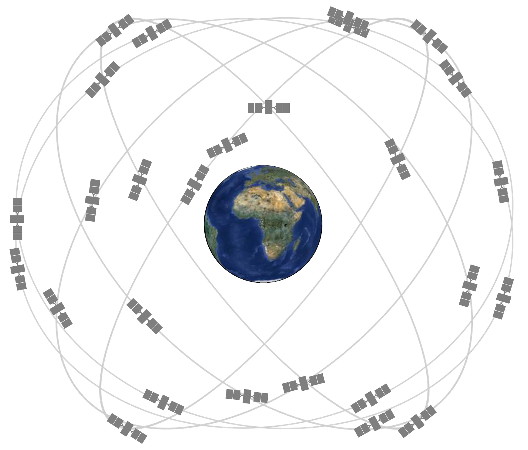
The GPS space segment consists of a constellation of 24 satellites, 21 operational satellites and 3 spare satellites, shown in Fig. 4.2. Four satellites are equally spaced in each of the six orbital planes with an orbit inclination of 55°. The difference between the ascending nodes of each orbital plane is 60° and the difference in the argument of latitude for satellites in the same orbital planes is 30°. This ensures that at least four GPS satellites can be visible at any time and any location around the world. The average orbital altitude of the GPS satellites is approximately 20,200 km, and their orbital period is approximately 11 h 58 min 2 s. For more information about GPS, please refer to http://www.gps.gov/.

Constellation of the GPS system
The first GPS satellite was launched in 1978, and the constellation of 24 MEO satellites was completed in 1994. Based on the launch time, the GPS satellites can be divided into six different types, namely, BLOCK I, BLOCK II/IIA, BLOCK IIR, BLOCK IIR-M, BLOCK IIF and GPS III satellites. The CDMA modulation is also adopted for GPS satellites to broadcast carrier signal in the L1 band (1575.42 MHz) and L2 band (1227.60 MHz). The open civil C/A code is modulated on carrier L1, and the encrypted P(Y) code for military uses is modulated on carrier L2 (ICD-GPS-200J 2018).
To further expand the GPS civil market and better serve military demands, the GPS modernization program was promoted by the US government. As shown in Table 4.2, the modernization of the GPS navigation signal and satellite constellation includes:
-
(1)
Broadcasting a new civil navigation signal and new military code (M code). The second civil pseudorange code L2C was introduced on BLOCK IIR-M satellites in 2005, and the third carrier frequency L5 (1176.45 MHz) was added on BLOCK IIF satellites in 2010. In 2016, the GPS III satellites began to broadcast three GPS carrier frequencies (L1, L2 and L5) with four civil navigation codes (C/A, L2C, L5 and L1C), among which the L2C was mainly designed for commercial applications. L5 was developed to meet the demands of navigation users in the field of safety-of-life-related transportation and other high-precision applications, and L1C was designed for compatibility and interoperability between GPS and other GNSSs.
-
(2)
Launching the new generation GPS III satellites to gradually replace the earlier satellites. The GPS III satellites were no longer able to implement the Selective Availability (SA) policy and a laser prism reflector was carried onboard to separate the satellite orbit and clock errors. The lifespan of the GPS satellites was also extended.
Until 2016, the GPS ground control segment consisted of one MCS, one backup MCS, 15 globally distributed monitoring stations, 11 uplink stations and the auxiliary communication network, shown in Fig. 4.3. Its MCS was located in Colorado, US. The ground control segment upgrade was included in the GPS modernization program and consisted of the following main aspects: (1) the Legacy Accuracy Improvement Initiative (L-AII) plan completed in 2008; ten GPS monitoring stations that belonged to the National Geospatial-Intelligence Agency (NGA) were added to the ground monitoring network to improve the forecasting accuracy of the GPS broadcast ephemeris; (2) the Architecture Evolution Plan (AEP) for MCS IT upgrade and the Launch and early orbit, Anomaly resolution, and Disposal Operations (LADO) plan for monitoring out-of-operation satellites in 2007; and (3) the Next Generation Operational Control System (OCX) plan implemented in 2010.

GPS ground control segment
The major function of the GPS user segment, including GPS receivers and hand-held terminals, is to track GPS satellites and compute the three-dimensional positioning, velocity and time for users. Users can receive two types of GPS positioning services: standard positioning service (SPS) and precise positioning service (PPS), shown in Table 4.3. SPS is free for all users. The positioning and timing services are obtained with C/A code on L1 and the broadcast ephemeris. PPS is aimed at serving the military and authorized users, and the positioning and timing services are obtained using the ranging code modulated on both L1 and L2 (Grimes 2007).
2.3 GLONASS
GLONASS was developed by the USSR in 1976 and is now operated by Russia. With the first GLONASS satellite launched on October 12, 1982, the full constellation was completed and was put into operation at the beginning of 1996. However, due to the short satellite lifespan of only 2–3 years on average and the lack of adequate funding to launch supplementary satellites after the economic recession, there were only six operational GLONASS satellites on orbit in 2011, which severely impacts the normal use of GLONASS. With the recovery of the Russian economy, the GLONASS modernization program was initiated. At the end of 2011, the full 24-satellite constellation was restored for independent navigation and positioning capability.
The space segment of GLONASS consists of 21 operational satellites and 3 backup satellites, which are evenly distributed over three orbital planes with an inclination of 64.8°. The longitude of the ascending node of each plane differs by 120° from plane to plane. In each orbit plane, there are 8 satellites separated by 45° in argument of latitude (ICD-GLONASS 2008). At an altitude of 19,100 km, the orbital period is 11 h 15 min and 44 s. In September 2016, the number of operational satellites in orbit was increased to 27, 24 of which are GLONASS-M and GLONASS-K1 satellites with full operational capability. For more information about GLONASS, please refer to https://www.glonass-iac.ru/.
Frequency division multiple access (FDMA) modulation is used by GLONASS; thus, different satellites are distinguished by different frequencies. The frequencies of the civil signals G1 and G2 broadcasted by GLONASS satellites are as follows:
where K = −7, … 0.6 is the frequency number of each satellite. For any satellite, fK1/fK2 = 9/7. The frequencies of carriers G1 and G2 for military use are different than those for civil use. Pseudo-random-noise code is modulated on the carrier signal and is the same for each set of frequencies. Similar to GPS, the civil code C/A was initially modulated only on carrier G1 whereas the military code P was modulated on both carriers G1 and G2. Later, the C/A code was also modulated on carrier G2 of GLONASS-M satellites. In contrast to GPS, the GLONASS P code is not encrypted.
The original intention to adopt the FDMA system in GLONASS was to enhance the anti-jamming capability. However, this strategy prevented the promotion of commercialization of GLONASS. To improve the compatibility and interoperability with other GNSSs, GLONASS began to broadcast the CDMA signal. For example, the first GLONASS-K1 satellite launched in 2011 broadcasted FDMA signals in the G1 and G2 bands and the new CDMA signal in the G3 band (1202.025 MHz), marking the first step of GLONASS signal modernization. In the future, the development of GLONASS CDMA signals will mainly focus on the G1 and G2 bands. As an improved version of GLONASS-K1, the GLONASS-K2 satellite could broadcast civil FDMA ranging code in G1 and G2 as well as the civil CDMA ranging code in G1, G2 and G3. GLONASS constellation modernization also includes stability and performance improvement of the onboard atomic clock, satellite lifespan extension, and introduction of intersatellite laser ranging (shown in Table 4.4).
The GLONASS system control center (SCC) is located in Krasnoznamensk, Moscow. The GLONASS time reference is maintained by the central clock (CC-M) in Schelkovo. Five telemetry, tracking and command (TT&C) centers are evenly distributed in Saint Petersburg, Schelkovo, Yenisseisk, Komsomolsk and Ussuriysk in Russia. Although the GLONASS TT&C stations are not distributed worldwide, a high-accuracy broadcast ephemeris can be generated by the ground control segment because the longitudinal span of the Russian territory is large. In addition, some TT&C stations are also equipped with a laser station (LS) and other Monitoring and measuring stations (MS). The service performance of GLONASS system are summarized in Table 4.5.
2.4 Galileo
Galileo was developed in a collaboration between the European Union and the European Space Agency (ESA). Galileo is the first global navigation satellite system designed for civil uses. The space segment of Galileo consists of 24 operational satellites and 6 spare satellites, which will be positioned on three orbital planes with an inclination of 56°, and the ascending nodes on the equator are separated by 120°. The orbital altitude is 23,222 km, and the orbital period is approximately 14 h (ICD-Galileo 2008).
The development of Galileo can be divided into three phases: the development system testbed, in-orbit validation (IOV) and full operational capability (FOC). During the development system testbed phase, two experimental satellites, GIOVE-A and GIOVE-B, were launched in 2005 and 2008, respectively (known as the Galileo In-Orbit Validation Element, GIOVE). Later, four Galileo-IOV satellites were launched in 2011 and 2012. In 2014, the Galileo-FOC satellites began to be launched.
The ground control segment of Galileo comprises two parts: the ground mission segment (GMS) and the ground control segment (GCS). The GMS is mainly responsible for processing observations to generate broadcast ephemeris. One ground control center (GCC) is located in Fucino, Italy, and is mainly responsible for monitoring the satellite constellation along with the GCC in Oberpfaffenhofen, Germany. These two GCCs are responsible for coordination and control of the TT&C stations, several uplink stations (ULS) and the Galileo sensor stations (GSSs) distributed worldwide, to maintain routine operation of the control segment. Galileo attaches great importance to system augmentation and integrity, which helps ensure the positioning accuracy and reliability in the fields of aviation and other safety-of-life applications.
Galileo makes use of the CDMA system to broadcast carrier signals on four frequencies: E1, E5a, E5b and E6. Five types of services are provided by Galileo for users: the free open service (OS) similar to GPS SPS, the safety-of-life service (SoLS), the commercial service (CS), the public regulated service (PRS) and the search and rescue (SAR) service. Signal E1 supports OS/CS/SoL/PRS services, E6 supports CS/PRS services, E5a supports OS services, and E5b supports OS/CS/SoL services. The service performance of Galileo system are summarized in Table 4.6.
With the modernization of GPS and GLONASS and the deployment of BDS and Galileo, the GNSS constellations has developed from approximately 30 GPS satellites in the early stage to more than 100 GNSS satellites in September 2016, summarized in Table 4.7. RNSSs such as QZSS and NAVIC are also under development. As shown in Fig. 4.4, the global coverage and availability of satellite navigation system signals have been improved.

The number of in-orbit satellites in GNSSs and RNSSs
In addition, the frequencies and types of GNSS satellite signals are becoming increasingly abundant (as shown in Table 4.7). For example, the second civil ranging code L2C and the third frequency L5 have been gradually provided by modernized GPS satellites. In the future, GLONASS will simultaneously broadcast FDMA, CDMA, as well as the third frequency signal G3. BDS provides signals in three frequencies of the full constellation and Galileo could broadcast carrier signals on four frequencies and 10 ranging codes. There are over 75 types of measurements (Gurtner and Estey 2013). To meet the ever-growing demand for GNSS civil applications, the third frequency signals L5 and G3 that are used for safety-of-life applications were designed by GPS and GLONASS, respectively; as a civil GNSS, Galileo gave high priority to aviation, safety-of-life and SAR applications at the beginning of its development.
3 GNSS Augmentation Systems
As described in Sect. 4.2, the accuracy of GNSS is rather limited and cannot meet the required positioning accuracy, time latency, reliability and integrity needs of higher-level users. The GNSS differential positioning technique and GNSS augmentation system strategy address this issue. In GNSS differential positioning, the observations of GNSS reference stations are used to model the error sources such as the ionospheric, tropospheric, satellite orbit and clock errors. These errors are then mitigated from the observation of users in real-time or post-processed mode to improve the accuracy and reliability of positioning. To meet the demands of different users, several different kinds of GNSS high-accuracy and real-time positioning systems have gradually been developed, including the wide-area differential augmentation system, the global/wide-area precise positioning system, the local area differential augmentation system and the local area precise positioning system (summarized in Table 4.8).
3.1 Wide-Area Differential Augmentation System
In the wide-area differential augmentation system, GNSS satellites are monitored with a ground tracking network and the raw observations are transferred to the master control center through communication links. The master control center models the errors of the GNSS raw observations and divides the errors into satellite orbit, clock, and ionospheric errors, which are formatted and broadcasted to users in the service region through communication links. The positioning accuracy can be improved by using the wide-area differential corrections. With uniform precision over broad coverage, the positioning accuracy of the wide-area differential augmentation system is independent of the distance between the user and the reference station. Several wide-area differential augmentation systems have been established worldwide, e.g., the Wide Area Augmentation System (WAAS) of the Federal Aviation Administration (FAA), the European Geostationary Navigation Overlay Service (EGNOS), the Multi-functional Satellite Augmentation System (MSAS) of Japan, the GPS-Aided Geo Augmented Navigation (GAGAN) of India and the System Differential and Correction Monitoring (SDCM) of Russia.
3.1.1 WAAS
The GPS SPS could not meet the higher accuracy, integrity, continuity and availability demands of users in aviation and other fields. As a result, the FAA initiated the WAAS program. As a satellite-based augmentation system (SBAS) to serve North America, WAAS is aimed at providing GPS differential correction information through GEO satellites to augment the GPS SPS. In addition to applications in the field of aviation, the WAAS has also been widely applied to support PNT services.
As illustrated in Fig. 4.5, the WAAS currently consists of 3 wide-area master stations (WMS), 38 wide-area reference stations (WRS), 4 Ground Uplink Stations and GEO satellites. The WMS is responsible for calculating the differential corrections and monitoring the system integrity. The WAAS data processing center receives real-time GPS observations from the WRS and computes differential correction vectors using the RTG (Real Time GIPSY) software package developed by the JPL based on GIPSY-OASIS. The corrections include the satellite orbit error, satellite clock error and the ionospheric error. Since these differential corrections are expressed as vectors, the precision of positioning within the areas covered by the wide-area differential system is equivalent, in contrast to the local-area differential system. The corrections are uploaded to GEO satellites through uplink stations and broadcast to users in RTCA format to improve positioning accuracy. The nominal positioning accuracy of WAAS (with 95% reliability) is better than 7.6 m in the horizontal and vertical directions. The horizontal and vertical positioning accuracy of WAAS are better than 1.0 m and 1.5 m, respectively, in most regions adjacent to the US, Canada and Alaska.

3.1.2 EGNOS
EGNOS is a joint program of the European Space Agency (ESA), the EU and the European Aviation Safety Agency (EASA). The working principle of EGNOS is similar to that of WAAS. The difference is that EGNOS broadcasts differential corrections and integrity information for GPS as well as the differential corrections for GLONASS. The EGNOS differential correction information is calculated using software developed from BAHN, the ESA-owned precise positioning and orbit determination software, and broadcasted by GEO satellites through the L band. The EU is considering extending the broadcast coverage from the EU to other regions, including countries neighboring the EU and Africa.
The EGNOS ground network consists of 39 ranging integrity monitoring stations (RIMSs), 4 mission control centers (MCCs) and 6 navigation land earth stations (NLESs). The 4 MCCs are located in Torrejon, Spain, Gatwick, England, Langen, Germany, and Ciampino, Italy. EGNOS presently provides three types of service: (1) free open service since October 2009, with positioning accuracy of 1–2 m; (2) safety-of-life service since March 2011, with positioning accuracy of 1 m; and (3) data access service since July 2012, with positioning accuracy better than 1 m.
3.1.3 MSAS
MSAS was jointly developed by the Japan Civil Aviation Bureau (JCAB) and Japan’s Ministry of Land, Infrastructure and Transport, mainly to provide communication and navigation services for Japanese aviation users. MSAS covers all flight service areas of Japan, and can broadcast meteorological information to mobile users in the Asia-Pacific region. The space segment of MSAS consists of two multifunctional transport satellites (MTSats), which are second generation Himawari satellites, the geostationary meteorological and environmental survey satellite developed by Japan. The two MTSats are positioned at 140° E and 145° E. The Ku and L bands are the two frequencies; the Ku band is mainly used to broadcast high-speed communication information and meteorological data. Similar to the GPS L1 frequency, the L band is mainly used for navigation services. The working principle of MSAS is similar as those of WAAS and EGNOS, and the RTG software authorized by JPL is used for data processing. From its initial operation in September 2007, MSAS remarkably improved the navigation service performance for Japanese airports located on remote islands and met the precision demand for the nonprecision approach specified by the International Civil Aviation Organization (ICAO).
3.1.4 GAGAN
The GAGAN system was jointly developed by the Indian Space Research Organization (ISRO) and the Airports Authority of India (AAI). The space segment of GAGAN consists of two GEO satellites positioned over the Indian Ocean. Two bands are applied in GAGAN: the C band is used for TT&C application and the L band is used to broadcast navigation information. The frequency of the L band is identical to that of the GPS L1 (1575.42 MHz) and L5 (1176.45 MHz); thus, GAGAN is compatible and interoperable with GPS. The GAGAN signal covers the whole Indian continent, providing users with GPS signals and differential corrections to improve the GPS positioning accuracy and reliability for Indian airports and other aviation applications. The key technique and core algorithm of GAGAN is also based on technical support from the JPL. The ground segment of GAGAN consists of a master station located in Bangalore, an uplink station and eight reference stations located in Delhi, Bangalore, Ahmedabad, Calcutta, Jammu, Port Blair, Guwahati and Thiruvananthapuram.
3.1.5 SDCM
Serving as the GLONASS satellite navigation augmentation system, Russia began developing the SDCM system in 2002 with an aim of providing differential augmentation information for GLONASS and other GNSSs. The space segment of SDCM consists of three GEO satellites, also called the Russian civil data relay (Luch/Loutch) satellites. The three satellites are known as Luch-5A, Luch-5B and Luch-5, located at 167° E, 16° W and 16° W, respectively.
3.2 Global Differential Precise Positioning System
The global differential precise positioning technique was developed from the wide-area differential GNSS and the precise point positioning technique. In global differential positioning systems, the GNSS pseudorange and carrier phase observations are collected by globally distributed GNSS dual-frequency monitoring stations and transferred to data processing centers through a real-time data transmission network to calculate the real-time precise satellite orbit, clock error and ionospheric corrections. Using the corrections, a user could realize decimeter to centimeter level precise positioning around the world. The wide-area differential augmentation system mainly serves navigation users with the pseudorange observations whereas the global precise positioning system mainly targets positioning users with the carrier phase observations. Well-known established representative global differential precise positioning systems include the global differential GPS (GDGPS) system applied for satellite orbit determination, scientific research and high-end commercial services, the StarFire system developed by NavCom, OmniSTAR and SeaStar by Fugro, CenterPoint RTX by Trimble and Veripos by Subsea7.
3.2.1 GDGPS
GDGPS is the global precise positioning system developed by the National Aeronautics and Space Administration (NASA) of the United States. As shown in Fig. 4.6, the ground monitoring network of the GDGPS consists of more than 200 real-time monitoring stations all over the world. These monitoring stations transmit real-time data to the GDGPS processing center at 1 Hz frequency. Among the tracking stations, over 75 monitoring stations belong to the JPL. They are evenly distributed worldwide and equipped with three-frequency receivers. The time latency of the GDGPS from receiving observations to generating and broadcasting real-time differential correction products is approximately 5 s. The real-time differential correction products can be broadcasted in a variety of ways, including through the Internet, a VPN, T1, frame relay, modem and satellite broadcasting.

(source http://www.gdgps.net/)
The real-time tracking network of the GDGPS
The JPL-developed RTG software is adopted in the GDGPS, with the state-square approach proposed by the JPL as its core algorithm. Based on the real-time dual-frequency GPS observation data collected by GDGPS monitoring stations worldwide, precise satellite orbit and clock errors are determined and compared with relevant parameters in the GPS broadcast ephemeris to generate differential corrections. The corrections are broadcasted to users for precise point positioning. The GDGPS can provide decimeter-level positioning and subnanosecond-level time transfer for dual-frequency GPS receivers over the globe. Compared with traditional differential positioning services, the positioning accuracy has been improved by one order of magnitude. The single-frequency users can also use the global ionospheric TEC maps provided by the GDGPS to implement ionospheric correction and improve positioning accuracy.
3.2.2 StarFire
In the early stage, StarFire was designed to provide independent wide-area differential augmentation services for precision agriculture in North America, South America, Europe and Australia. The early StarFire system was similar to WAAS and EGNOS, except that StarFire users must be equipped with high-quality dual-frequency GPS receivers to eliminate ionospheric delay, and should adopt the wide area correction transform (WCT) technique that was developed on the basis of NavCom.
In 2001, an agreement was reached between NavCom and NASA/JPL to upgrade StarFire into a global dual-frequency GPS precise positioning system based on the RTG technique. Continuous real-time positioning services with subdecimeter accuracy can be accessed anywhere and anytime around the world. In addition to the RTG technique, StarFire can access observation data from the NASA/JPL global monitoring network to augment the StarFire ground monitoring network. In addition, StarFire makes use of the International Maritime Satellite (INMARSAT) to broadcast differential signals to global users through the L band. StarFire users equipped with L band communication receivers can track and observe GPS satellites and receive the differential correction signals broadcasted by INMARSAT.
RTG/RTK is a new real-time differential positioning mode recently launched by NavCom. The disadvantage of a relatively long initialization time in RTG can be overcome by using RTK. If lock-lose or communication interruption of data links occur during RTK, real-time positioning services can be continuously provided by the RTG with centimeter-level positioning accuracy. After restoring the signal tracking and data link communication in RTK, the positioning result of the RTG can be used as the initial value for rapid searching and integer ambiguity resolution. The disadvantage is that at least two RTG/RTK combined dual-frequency receivers are required on the user side for real-time positioning.
3.2.3 OminiSTAR/SeaStar
OmniSTAR and SeaStar are real-time global differential systems developed by the Fugro company. OmniSTAR is mainly used in land and aviation applications and SeaStar was established to meet the demands for high kinematic positioning in marine applications. OmniSTAR currently provides four types of differential GPS positioning services with different accuracies, VBS, HP, XP and G2, among which the G2 service can support both GPS and GLONASS. OmniSTAR has been widely applied in agriculture, GIS, aviation, surveying and mapping, asset tracking and monitoring and, thus, occupies a considerable market share in differential GPS services.
SeaStar primarily serves the offshore oil and gas exploitation industry to meet the demands for submeter and decimeter-level kinematic positioning with high accuracy and reliability under special circumstances. It can provide G2, XP2, SGG and standard L1 services for GPS and GLONASS, as well as XP service for GPS. The latest G4 service simultaneously supports GPS, GLONASS, BeiDou and Galileo.
3.2.4 CenterPoint RTX
CenterPoint RTX (Real-Time eXtended) is a global real-time differential system developed by the US company Trimble. It provides worldwide precise positioning services with a horizontal accuracy better than 4 cm for GPS, GLONASS and QZSS. Using the corrections broadcasted by the L-band satellite, the initialization time needed for positioning is less than 5 min.
3.2.5 Veripos
Established by the Subsea7 company, Veripos consists of more than 80 reference stations all over the world. The two control centers of Veripos are located in Aberdeen, Britain and Singapore. The Veripos Apex, Veripos Apex2, Veripos Ultra and Veripos Ultra2 can provide services with a positioning accuracy better than 10 cm, and Veripos Standard and Veripos Standard2 can provide a positioning accuracy better than 1 m. The latest Veripos Apex5 can provide augmentation services for GPS/GLONASS/Galileo/BDS/QZSS with a horizontal positioning accuracy better than 5 cm (within a 95% confidence level).
3.3 Local Area Differential Augmentation System
The local area augmentation system (LAAS) at airports is a typical local area differential augmentation system. Based on GPS real-time differential corrections, LAAS was established as an all-weather precision approach and landing system. It consists of reference stations, a central processing station and airborne equipment. GPS satellites are continuously tracked by several reference stations located around the airport, and the central processing station receives the GPS observations to generate pseudorange differential corrections and integrity and precision approach and landing data, which are encoded and broadcasted to the airplane through VHF data links. Based on the GPS observations, differential corrections and integrity information broadcasted by LAAS, the airborne equipment can improve the navigation accuracy, integrity, continuity and availability to realize precision approach category I (CAT I) along a specified path. The ultimate goal of an LAAS is to provide CAT II and CAT III.
3.4 Local Area Precise Positioning System
In the local area precise positioning system, several GNSS reference stations are established in a certain region (district, city or country) and high-accuracy positioning service is provided to users within its coverage by taking advantage of differential corrections through a wired/wireless real-time data communication link. The local area precise positioning system can be categorized into two operational modes, single reference station mode and multiple reference stations mode. In single reference station mode, a reference station directly broadcasts high-precision carrier phase measurements to users at the rover station. The rover station receives the measurements and realizes precise positioning based on the differential positioning technique. The positioning accuracy of single reference station mode is at the centimeter level, which can meet the demands of applications within a small area.
The continuously operating reference station (CORS) system is a local area precise positioning system operated in the multiple reference station mode. CORS consists of continuously operating GNSS reference stations, which are interconnected by computer, data communication and the Internet. The observation data (carrier phase and pseudorange) at CORS reference stations are transmitted to the data processing center through the communication link in real-time. The data from the reference network are then uniformly processed to calculate and model the real-time corrections for various GNSS errors within the region, such as the satellite orbit/clock error an ionospheric and tropospheric error. The corresponding observation data and GNSS error model are broadcasted by the data processing center to users at the rover station for high-accuracy positioning. Many countries have established their own CORS systems at the national level, including the US, Germany, England, Australia, Japan, and Canada. Brief introductions to the US CORS and EPN in Europe are provided as representative examples.
3.4.1 US CORS
The establishment of CORS in the US was led by the National Geodetic Survey (NGS). More than 200 agencies and organizations have been involved in this program. The three largest CORS networks include the national CORS network, the operational CORS network and the California CORS network. In 2015, the US CORS consisted of more than 2000 reference stations. Most of the stations are distributed in American. However, several stations are located in Canada, Mexico, Central America and North America. The US CORS provides users with coordinates under the International Terrestrial Reference Frame (ITRF) and the 1983 North American Datum (NAD83), as well as raw observations and satellite orbit products. Real-time differential positioning service is also available in some areas, e.g., the San Diego real-time network.
3.4.2 EPN in Europe
The EUREF permanent network (EPN) in Europe is a cooperative regional continuously operating network established by the European Commission of the IAG. The EPN was composed of 250 permanent reference stations in 2016. The workflow of the EPN is as follows: the reference stations are divided into several subnetworks with independent system operation centers. Several system operation centers constitute a regional data center, and the data from regional data centers are gathered into the European regional center, which transfers the data products to the IGS data center, regional data centers and various kinds of users. The EPN provides users with centimeter-level coordinates and velocity in ITRF and EUREF, as well as zenith tropospheric products for the reference stations. In addition, the EPN can be applied to monitor crustal deformation, sea level changes, and in numerical weather prediction (NWP).
GNSS augmentation systems have achieved significant developments in the aspects of the accuracy, integrity, coverage and differential mode. The positioning accuracy of GNSS augmentation systems has improved from meter-level, as for WAAS, EGNOS and MSAS, to real-time decimeter-level and post-processed centimeter-level, e.g. StarFire and OmniStar. The GNSS augmentation system has been extended from regional coverage to seamless global coverage. The early GNSS augmentation systems provided users with correction based on one differential approach whereas the current system can provide users with high-precision positioning with corrections derived from multiple differential approaches. As an effective supplement to GNSS, the GNSS augmentation systems have greatly improved the GNSS SPS performance to meet the ever-growing demands for integrity, continuity and availability of navigation systems. They also benefit many other applications such as navigation, aviation, maritime, industry, and precision agriculture.
4 Applications in Digital Earth Case Studies
GNSSs have been widely applied in navigation for vehicles, offshore ships, aero craft and aerospace vehicles, geodesy, oil exploitation, precision agriculture, precise time transfer, Earth and atmospheric sciences, and many other fields. Its applications in the establishment of space-time geodetic datum, high-precision positioning and location-based services are introduced below.
4.1 Terrestrial Reference System
As a result of inexpensive GNSS receivers, densely distributed tracking stations and the high accuracy performance, GNSSs have played an important role in the establishment and maintenance of geodetic datum. The location and movement of a point on the Earth’s surface must be expressed in a terrestrial reference system (TRS) attached to the Earth (also called the Earth-centered Earth-fixed system). The origin of the TRS is usually defined as the center of mass of the Earth, the Z axis is aligned with the international reference pole, the X axis is coincident with the Greenwich zero meridian, and the Y axis is orthogonal to the Z and X axes in the right-handed sense. As an ideal realization of the TRS, the TRF is comprised of a set of stations distributed on the Earth’s surface with precisely known coordinates. The TRF is of great importance for geodesy, geophysics and space research. GNSS is an important data source to establish and maintain the TRF.
The widely used ITRF was established based on space-geodetic observations including GNSS, very long baseline interferometry (VLBI), satellite laser ranging (SLR), and Doppler orbit determination and radio positioning integrated on satellite (DORIS). As a realization of the International Terrestrial Reference System (ITRS), the ITRF can provide datum definitions (including origin, orientation and scale) for other global and regional TRS. Since 1988, more than ten versions of the ITRF have been released by the IERS, the latest version of which is the ITRF2014 released on January 2016 (Altamimi et al. 2016).
Different TRFs are adopted by different GNSSs. They include the World Geodetic System 1984 (WGS84) for GPS, Parametry Zemli 1990 (PZ-90) for GLONASS, Galileo terrestrial reference frame (GTRF) for Galileo and the BeiDou coordinate system (BDCS) for BDS. Most of the TRFs are aligned to the ITRF. The positioning results based on GNSS broadcast ephemeris are expressed in the corresponding TRF. As the TRF for GPS broadcast ephemeris, WGS84 has been refined several times by the US DoD, resulting in WGS84 (G730), WGS84 (G873), WGS84 (G1150), WGS84 (G1674) and WGS84 (G1762). PZ-90 is the TRF for GLONASS broadcast ephemeris. Successive versions of PZ-90, PZ-90.02 and PZ-90.11, have been released (Zueva et al 2014). GTRF is the TRF for the Galileo broadcast ephemeris, and GTRF07v01, GTRF08v01, GTRF09v01 and GTRF14v01 have been released (Gendt et al. 2011).
To unify the positioning results expressed in different TRFs, a 7-parameter Helmert transformation should be applied:
where T1, T2, T3 are the translation parameters for the X, Y and Z axes, respectively, D is the scale factor, and \( \alpha_{1} ,\alpha_{2} ,\alpha_{3} \) denote the Euler angles of rotation for the X, Y and Z axes. \( R_{i} \left( {\alpha_{i} } \right) \) indicates the rotation matrix constituted by the rotation angles \( \alpha_{i} \) for axis i, which can be expressed as:
For the transformation parameters between different ITRF versions, please refer to Table 4.1 in the IERS Conventions (2010). The transformation parameters between ITRF2008 and WGS84, PZ-90, and GTRF versions are shown in Table 4.9. The definitions of the transformation parameters are the same as in Eq. (4.3).
4.2 Time System
Three types of time systems are commonly used. Their time scale are based on the Earth’s rotation, e.g., the universal time (UT), the revolution of the Earth around the sun, and the electron transition frequency of atoms, e.g., the International Atomic Time (TAI). Coordinated Universal Time (UTC) uses the SI second of atomic time as its fundamental unit and is kept in time with the UT.
Atomic time is a time system based on the electromagnetic oscillation generated by the atomic transition inside substances. The Standard International (SI) second is defined as the time that elapses during 9,192,631,770 cycles of the radiation produced by the transition between two levels of the cesium 133 atom. The International Atomic Time (TAI) is the time system determined by the SI second, with the same origin as UT2 on 0 h 0 m 0 s, January 1, 1958. As a continuous and uniform time scale, TAI is maintained by the Bureau International des Poids et Mesures (BIPM) using the atomic clocks of 400 national laboratories worldwide.
Universal Time (UT) is defined as the hour angle of mean sun relative to the Greenwich meridian plus 12 h. UT can be divided into three types. UT0 is directly determined from astronomical observations. Correcting the Earth’s polar motion from UT0 yields UT1 whereas UT2 is obtained by correcting the seasonal variations of the Earth’s rotation from UT1. UT1 defines the orientation of the average Greenwich meridian with respect to the mean equinox and thus represents the real rotation of the Earth. Since UT1 has a tendency of long-term slowdown, the difference between UT and the atomic time will grow increasingly larger. To avoid such an inconvenience, Coordinated Universal Time (UTC) has been adopted since 1972 based on the second length of TAI. It is a uniform but discontinuous time scale, and the difference between UTC and UT1, which is known as the leap second, is maintained within 0.9 s. The leap second with respect to UT1 is released by the IERS, and the relationship between TAI, UTC and leap seconds can be described as
GNSSs are also an important technology to establish and maintain time systems. The GNSS time system is atomic time, in which the TAI second length is used and maintained jointly by high-accuracy atomic clocks onboard the GNSS satellites and implemented in the ground system. With an origin at 00:00 on January 1, 1980, the GPS Time (GPST) is adopted for GPS system. To ensure uniform continuity, there is no leap second in GPST and the constant difference between TAI and GPST is maintained as 19 s.
GLONASS makes use of GLONASS Time (GLONASST), which is synchronized to the UTC (SU) of Russia but biased by 3 h to match the local time zone of Moscow: GLONASST = UTC (SU) + 3 h. Unlike GPST, there are leap seconds in GLONASST.
Galileo adopts the Galileo System Time (GST) with an origin at 00:00 on August 22, 1999 (UTC time). The difference between GST and UTC at the starting epoch is 13 s and there is no leap second to maintain the uniform continuity of GST.
BDS makes use of BeiDou Time (BDT) with an origin at 00:00 on August 22, 1999 (UTC time). The difference between BDT and TAI at the origin moment is 33 s. BDT is counted with the week number (WN) and seconds of week (SOW). Similar to GST, no leap second is adopted to maintain uniform continuity of BDT. BDT is steered to UTC (NTSC).
The transformations between GPST, GLONASST, BDT, GST and UTC are as follows:
where leap is the leap second of UTC with respect to TAI, as shown in Eq. (4.4); C0, C1, C2, C3 are the daily deviation values of GPST, GLONASST, BDT and GST relative to UTC, respectively, provided by the BIPM. The accuracies of C0 and C1 are approximately 10 ns and several hundreds of ns, respectively (ftp://ftp2.bipm.org/pub/tai/other-products/utcgnss/utc-gnss).
High-accuracy UTC time can be obtained through GNSS data. The GNSS common-view technique has been used by the BIPM for many years as one of its main techniques for international time transfer. It has the advantages of low equipment cost, high accuracy and convenient operation. In this technique, the time difference between two clocks, A and B, is determined by simultaneous observation of a third clock on a GNSS satellite. Each station observes the time difference between its clock and the GNSS time plus a propagation delay, which can be largely removed by using one-way GNSS time transfer procedures. By exchanging data files and performing a subtraction, the time difference between the two receiving stations is obtained.
The GNSS timing technique has been widely applied to time and frequency synchronization in the communication, finance and power industries in China. In the communication field, time synchronization for the whole communication network is realized through installation of GNSS timing terminals, so the billing time can be ensured to be consistent and accurate. For the frequency synchronization networks of China mobile, China telecom and China Unicom, the first-level reference clock and part of the second-level/third-level/micro-synchronization-node clock are equipped with a built-in GNSS reception module and external GNSS receivers. The time synchronization networks are also equipped with dual-mode GNSS timing receivers.
In the power industry, time and frequency synchronization for the substation network can be provided by GNSS timing. The time systems from power transmission network to power computer network in the Chinese power industries mainly use GPS as the master clock for timing and synchronization. On December 1, 2017, the ‘Technical specification of time synchronization system and equipment for smart substation’ (GB/T 33591-2017) became officially effective, in which the BDS is adopted as the main technique for time synchronization. By the end of 2017, there were nearly 900 sets of dispatching automation master station systems (in 11 categories) that could receive BDS signals in the domestic power grid control network, and more than 15,000 sets of GPS timing equipment have been updated to be compatible with the BDS.
4.3 High-Precision Positioning
The accuracy of single-point positioning based on broadcast ephemeris is only 10 m and is influenced by the unmodeled errors and noise of the pseudo-ranges. It cannot meet the requirements of many applications and limits the use of GNSSs. Differential GNSS techniques were developed to improve the positioning accuracy to decimeter-level. DGNSS/RTK and precise point positioning (PPP) are two commonly used high-precision differential positioning methods. The basic principle uses one or more reference stations with precisely known positions to model the observation errors, including the ionospheric and tropospheric delay and satellite clock and orbit errors to improve the accuracy and reliability of positioning for users.
The high-precision GNSS positioning algorithm was developed from the single-station pseudorange differential approach and carrier phase differential approach into a real-time carrier phase differential approach based on multiple reference stations (network RTK), PPP, and PPP with fixed ambiguity resolution (PPP-AR), improving the resolution accuracy and extending the application modes. The differential algorithms can be categorized into location differential, pseudorange differential and carrier phase differential techniques according to the differential observations adopted. The differential algorithms can also be classified as single-station differential, local area differential, wide area differential, or global real-time high-precision PPP based on the effective range of the differential corrections. They can be categorized into satellite-based and ground-based differential augmentation based on the type of broadcast link. Finally, the differential algorithms can be categorized into the state space representation (SSR) differential method and the observation space representation (OSR) differential method according to the differential model algorithm and parameters.
The PPP (SSR) and the network RTK (OSR) are the two major techniques in high-precision GNSS positioning services. The network RTK method, also known as the RTK method with multiple reference stations, usually needs more than three GNSS CORS stations within a certain region. Taking one or several stations as the reference stations, the distance dependent errors are modeled as regional OSR corrections. The differential corrections are provided to the rover stations in real time for precise positioning. The network RTK method can be classified into four types, including the virtual reference station (VRS) method, the master auxiliary concept (MAC) method, the Flächen Korrektur parameter (FKP) method or the combined bias interpolation (CBI) method, according to the OSR differential corrections used.
The VRS method is the most widely used network RTK technique at present. A virtual reference station is established near the rover station. Observation of the virtual reference station is generated using the real observation of the surrounding reference stations plus the regional error corrections. By receiving the observations of the virtual reference station, users can realize high-accuracy real-time positioning with the single-station RTK method. In the MAC method, corrections from the reference network can be divided into two categories: corrections closely correlated with the carrier frequency, e.g., the ionospheric delay, and corrections independent of the carrier frequency, e.g., the orbit error, tropospheric error, and multipath effect. The integer ambiguity of the reference network is initially fixed to ensure a uniform integer ambiguity reference for all the reference stations. The correction difference between the auxiliary station and the master station is calculated and broadcasted to the rover station. The principle of the FKP method is to estimate nondifferential parameters for each reference station in real time and generate the network solution. The spatial correlation error of the ionosphere and the geometric signal inside the network is then described with regional parameters. Based on these parameters and locations, the rover station computes the error corrections and realizes precise positioning. The FKP method has been widely applied in Germany, the Netherlands and other European countries. The CBI method does not distinguish ionospheric delay from tropospheric delay and other types of errors when calculating the corrections of the reference stations. The corrections for each reference station are not broadcasted to the users. Instead, the observation data of all the reference stations are gathered to select, calculate and broadcast the comprehensive error corrections to the user.
For specific regional users, the accuracy of network RTK can achieve centimeter-level. However, due to the spatial restriction of OSR differential correction methods, the distance between reference stations in network RTK can generally be no more than 70 km. Therefore, it would be very costly to establish a wide-area real-time service system to serve a large number of users using the network RTK method. The PPP technique based on the wide-area (global) tracking network can realize high-accuracy positioning with only a few reference stations in a wide area. It could effectively overcome the disadvantages of network RTK. However, although PPP could provide positioning service with the same accuracy all over the world, it has the disadvantages of slightly lower positioning accuracy and relatively longer initialization time than network RTK.
Based on precise satellite orbit and clock error data, the PPP method could realize decimeter-level to millimeter-level positioning accuracy using carrier phase and pseudorange observations collected by a single GNSS receiver. Only the high-precision satellite orbit and clock errors are needed to obtain high-precision positioning for any station at any location and the positioning error is homogenous worldwide. Thus, PPP has been widely used in crustal deformation monitoring, precise orbit determination, precise timing, earthquake/tsunami monitoring and warning, and many other fields. As an extension of the standard PPP technique, PPP-AR can obtain ambiguity-fixed coordinates through restoring the integer characteristics of the nondifferential ambiguity. Its accuracy is equivalent to that of RTK.
In China, the first-generation BDS augmentation system was formally approved on April 28th, 1998, with the goal of providing GPS wide-area differential and integrity service for users based on BDS-1. It aims to improve the GPS accuracy and reduce the risk of using GPS. The first-generation BDS augmentation system (the first phase of construction) was completed and began trial operation in 2003. During this period, the augmentation system operated stably and provided real-time GPS differential correction and integrity service for various users in the service region. The positioning accuracy and integrity warning capability were basically in accordance with the design indicator requirements. In recent years, research and development of a wide-area real-time precise positioning prototype system in China and the neighboring areas have been carried out with the support of the national 863 program. As a key project in the field of Earth observation and Navigation Technique under the National High-tech Research and Development Program (863 program) in 2007, the ‘wide-area and real-time precise positioning technique and prototype system’ was jointly undertaken by the China Satellite Communications Corporation (China Satcom), China Center for Resources Satellite Data and Application, and Wuhan University. Based on the wide-area differential and PPP technique, the satellite navigation augmentation service is realized with a positioning accuracy of better than 1 m for land, ocean and air transport in China.
The construction of CORS around world has entered into a new era. A provincial-level CORS system in Jiangsu and Guangdong provinces has been established in China. CORS systems have also been established in various large- and medium-sized cities, e.g., Beijing, Shanghai, Tianjin, Chongqing, Nanjing, Guangzhou, Shenzhen, Wuhan, Kunming, Jinan, Qingdao, Suzhou, Changzhou, Hefei, Dongguan, and Zibo. There are more than 2200 CORS stations in China. CORS systems may be upgraded to install BDS receivers. High-precision surveying can be conducted through these CORS systems with high efficiency and less man-power than traditional technology such as a total station. The CORS system is currently a vital part of surveying and mapping activities around the world, including urban planning, land surveying and mapping, cadastral management, urban and rural construction, and mining surveying.
The differential GNSS technique can support cadastral surveying to establish property boundaries, which is of great importance for fiscal policies such as land taxation. In the different construction stages of a building or civil engineering project (such as a highway, motorway, bridge, underground tunnel, railway, reservoir or embankment), GNSS positioning can be used to automatically control the construction equipment. GNSSs are also used to define specific location points of interest for cartographic, environmental and urban planning purposes. GNSSs play an important role in measurement and calculation at each stage of mine exploitation, including safety checks. GNSSs are used to monitor critical infrastructure and the natural environment to prevent major disasters and promptly intervene in case of emergency. GNSSs can support a wide range of activities in marine surveying, such as seabed exploration, tide and current estimation and offshore surveying.
4.4 Location-Based Service
Location-based service (LBS) systems work independently or cooperate with mobile terminals to provide real-time and post-processed positioning and timing service for various users through different communication networks. LBS relies on GNSS and augmentation systems to provide uniform space-time datum. Other assisted navigation and positioning techniques are also incorporated to improve the anti-jamming capability and availability of LBS. Through communication networks, e.g., the internet and mobile internet, LBS can provide users with positions, attitude, velocity and time synchronization services.
The workflow of a typical LBS system can be designed as follows: the GNSS wide-area augmentation system receives a real-time data stream from various GNSS tracking networks, generates the wide-area and regional satellite navigation augmentation signals, and provides them to the authorized public users through broadcasting systems controlled by a service provider. GNSSs are ‘outdoor’ positioning techniques, as the GNSS signal is affected by strong attenuation and multipath caused by complex indoor environments. In severe environments, the GNSS signals cannot be captured. Thus, the location of users inside a building should be determined by an indoor positioning system using WIFI, Bluetooth, INS, magnetic fields, and virtual beacons. The information integration platform receives the satellite navigation augmentation signals and merges them with geographical data to provide users with comprehensive location-based value-added service through LBS providers. As an integration of social networks, cloud computing and the mobile internet, LBS could become the core element of a series of significant applications, e.g., intelligent transportation systems (ITS), precise agriculture, intelligence manufacturing and smart cities. GNSS-enabled LBS applications are mainly supported by smartphones.
ITS refers to efforts to add information and communications technology to transport infrastructure and vehicles in an effort to manage factors that are typically at odds with each other, such as vehicles, loads, and routes, to improve safety and reduce vehicle wear, transportation times, and fuel consumption. GNSSs play an important role in ITS applications such as traffic control and parking guidance by providing accurate and reliable positioning. The low-cost high-precision GNSS receiver has a big potential market in ITS. The low-cost GNSS receiver can also be integrated with an inertial navigation system (INS) to develop an autonomous navigation system for general aviation (GA). General aviation is the term used to describe all aviation except government and scheduled-airline use.
The accuracy of GNSS SPS is only approximately 10 m. It cannot tell users the optimal lane to get to their destination, especially in dense urban environments such as multilane roads and highways. With the aid of an LBS system, lane-level navigation and positioning with meter-level accuracy can be realized. It will become the standard configuration for passenger vehicles and freight vehicles with hazardous chemicals in the future. The consortium within the EU-funded InLane project is working on the fusion between computer vision and GNSS technologies to achieve the required level of positioning that allows for the safe operation of autonomous vehicles (https://www.gsa.europa.eu/market/market-report).
The embedment of GNSS terminals in bicycle-sharing systems can result in more accurate and reliable positioning for better user experiences, especially in complex scenarios. The positioning accuracy can be improved from 50-100 m to approximately 3 m. The GNSS terminals can also support orderly parking. Currently, approximately half of the bicycle-sharing systems in China are equipped with GPS terminals. High-precision BDS positioning has also been adopted in driver training. It can automatically record the trail of the wheel at the centimeter level. Many driving test centers in China promote this technique.
The premise of precision agriculture is to adapt field operations to local variations in crop and soil conditions using state-of-the-art technology combined with knowledge-intensive field management. The positioning system is a part of precise equipment that consists of a differential global positioning system (DGPS) receiver, a radar velocity sensor, a wheel velocity sensor and an electronic compass. Precision positioning helps complete field applications faster and more productively, accurately, safely and comfortably, with less operator fatigue. GNSS is used in agriculture in a few key areas. As crops are harvested, a GNSS receiver connected to a yield monitor sensor records a coordinate along with the yield data. This data is combined and analyzed to create a map of how well different areas of the field are producing. When spreading fertilizer or planting, equipment operators have traditionally used markers such as foam or other visual aids to mark where they’ve been to try to avoid overlap. The assistance of GPS and onboard guidance systems such as a light bar, can further reduce overlap.
For many years, the leading technology for precision agriculture was GPS L1 receivers providing submeter precision. That precision can meet the requirements of applications at the submeter level, such as applying chemicals, field mapping and aerial spraying. However, high-precision applications such as auto-steer need centimeter precision. Historically, Hemisphere GPS (formerly CSI), Trimble Navigation, OmniSTAR, and smaller designers and system integrators have been the GNSS technology providers for precision agriculture. The world-wide agriculture market is booming. Auto-steer and other high-precision GNSS applications in agriculture have contributed to increased production capacity.
The GNSS navigation function in smart phones can record the wheel path and personal interests as well as the behaviors of pedestrians and drivers, providing large amount of social activity information. It should be regarded as an important source of big data on human activities and interests. In the future, with the application of high-accuracy navigation based on smart phones and the implementation of integrated indoor and outdoor location services, this big data will provide more abundant information. A 2013 Nature paper noted that the owner of a cellphone can be specified (with 95% probability) by analyzing the big data of the cellphone location tracks in a city with approximately 1,500 thousand people. LBS systems could also support applications such as geomarketing and advertising, fraud management and location-based billing, which require authentication of the position to protect app users.
LBS applications for healthcare are increasing. Healthcare needs are driving the diversification of wearables. For example, a GNSS-enabled haptic shoe allows for visually impaired users to set a destination in a smartphone app. The soles guide the user to the destination by vibrating in the front, back, or sides. Visually-impaired people or wheelchair users rely on a seamless navigation experience between outdoor and indoor environments. They need more high-precision horizontal and vertical position information (https://www.gsa.europa.eu/market/market-report).
In summary, there is a huge navigation and LBS market. The navigation and LBS network will also promote the development of industries such as national security, social security, energy conservation and emission reduction, disaster relief and mitigation, traffic and transportation, the IoT, resource investigation, and precision agriculture.
References
Altamimi Z, Rebischung P, Métivier L et al (2016) ITRF2014: A new release of the International Terrestrial Reference Frame modeling nonlinear station motions. Journal of Geophysical Research: Solid Earth 121(8): 6109–6131
BDS-ICD (2013) Space Interface Control Document. Open Service Signal. China Satellite Navigation Office. http://www.beidou.gov.cn/xt/gfxz/201812/P020181227529449178798.pdf. Accessed 13 December 2018
Gendt G, Altamimi Z, Dach R et al (2011) GGSP: realization and maintenance of the Galileo terrestrial reference frame. Advances in Space Research 47(2):174–185
Grimes JG (2007) Global positioning system precision positioning service performance standard. GPS Navster. Department of Defense. https://www.gps.gov/technical/ps/2007-PPS-performance-standard.pdf. Accessed 13 July 2019
Gurtner W, Estey U (2013). The Receiver Independent Exchange Format. http://nebula.wsimg.com/5d20c8382d99be2caba8884b018c8dbf?AccessKeyId=2D3610E97C8E55B553AE&disposition=0&alloworigin=1. Accessed 13 July 2019
ICD-Galileo (2008) Galileo open service, signal in space interface control document (OS SIS ICD). Edited by European space agency/European GNSS supervisory authority. https://www.gsc-europa.eu/system/files/galileo_documents/Galileo-OS-SIS-ICD.pdf. Accessed 13 July 2019
ICD-GLONASS (2008) Glonass interface control document. Russian Institute of Space Device Engineering, Moscow, Russia. https://www.unavco.org/help/glossary/docs/ICD_GLONASS_5.1_(2008)_en.pdf. Accessed 13 July 2019
ICD-GPS-200J (2018) Space Segment/Navigation User Interface Control Documents. https://www.gps.gov/technical/icwg/IS-GPS-200J.pdf. Accessed 13 July 2019
Zueva A, Novikov E, Pleshakov D et al (2014) System of Geodetic parameters. Parametry Zemli 1990, (PZ-90.11). Paper presented at UN International Committee on Global Navigation Satellite Systems. Working Group D: Reference Frames, Timing and Applications. Working Group Meeting
Author information
Authors and Affiliations
Corresponding author
Editor information
Editors and Affiliations
Rights and permissions
Open Access This chapter is licensed under the terms of the Creative Commons Attribution 4.0 International License (http://creativecommons.org/licenses/by/4.0/), which permits use, sharing, adaptation, distribution and reproduction in any medium or format, as long as you give appropriate credit to the original author(s) and the source, provide a link to the Creative Commons license and indicate if changes were made.
The images or other third party material in this chapter are included in the chapter's Creative Commons license, unless indicated otherwise in a credit line to the material. If material is not included in the chapter's Creative Commons license and your intended use is not permitted by statutory regulation or exceeds the permitted use, you will need to obtain permission directly from the copyright holder.
Copyright information
© 2020 The Author(s)
About this chapter

Cite this chapter
Shi, C., Wei, N. (2020). Satellite Navigation for Digital Earth. In: Guo, H., Goodchild, M.F., Annoni, A. (eds) Manual of Digital Earth. Springer, Singapore. https://doi.org/10.1007/978-981-32-9915-3_4
Download citation
DOI: https://doi.org/10.1007/978-981-32-9915-3_4
Published:
Publisher Name: Springer, Singapore
Print ISBN: 978-981-32-9914-6
Online ISBN: 978-981-32-9915-3
eBook Packages: Earth and Environmental ScienceEarth and Environmental Science (R0)