
Abstract
In boilers, there is a need of bent pipes to direct the flow of steam/air in and out of a boiler. Usually, bent pipes are preferred than welded pipes. When a pipe is bent, wall thickness of the pipe tends to decrease on the outer side of the bending. When a pipe is not bent properly, it leads to excess wall thinning. Wall thickness is the main criteria that govern the strength of a pipe, because whenever a high-pressure fluid flows through the bend it should withstand the pressure. In cold bending at normal temperature, various fillers are used to reduce the effect of wall thinning. In incremental hot bending, the effect of wall thickness has been studied by varying bend radius of the pipe and percentage change in wall thinning and its effects are observed.
Access this chapter
Tax calculation will be finalised at checkout
Purchases are for personal use only
References
Lynn, F.B.: Wall thinning during tube bending. Pines Technol. 1, 26–31 (2009)
Kale, A.V., Thorat, H.T.: Control of ovality in pipe bending. Paper presented at 5th international & 26th all india manufacturing technology, design and research conference (AIMTDR 2014), IIT Guwahati, Assam, India, Dec 12–14 2014
Agarwal, R.: Tube bending with axial pull and internal pressure. Ph.D. dissertation, Texas A&M University (2004)
Sedighi, M.: Role of filling material on defects of thin-walled tube bending process. J. Theoret. Appl. Mech. 52(1), 227–233 (2014)
Thinvongpituk, C., Poonaya, S., Choksawadee, S., Lee, M.: The ovalisation of thin-walled circular tubes subjected to bending. In: World Congress on Engineering, vol. 2, pp.2–4 (2008)
Li, H., Yang, H., Yan, J., Zhan, M.: Numerical study on deformation behaviours of thin-walled tube NC bending with large diameter and small bending radius. Comput. Mater. Sci. 45, 921–934 (2009)
Hu, Z., Li, J.Q.: Computer simulation of pipe-bending processes with small bending radius using local induction heating. J. Mater. Process. Technol. 91, 75–79 (2000)
Tang, N.C.: Plastic-deformation analysis in tube bending. Int. J. Press. Vessels Pip. 77, 751–759 (2000)
Yang, M., Zhan, M., Kou, Y.L.: Deformation behaviours of thin-walled tube in rotary draw bending under push assistant loading conditions. J. Mater. Process. Technol. 210, 143–158 (2010)
Kim, J.W., Naa, M.G., Park, C.Y.: Effect of local wall thinning on the collapse behaviour of pipe elbows subjected to a combined internal pressure and in-plane bending load. Nucl. Eng. Des. 238, 1275–1285 (2008)
Author information
Authors and Affiliations
Corresponding author
Editor information
Editors and Affiliations
Appendices
Appendix 1: Pipe Bending Terminologies and Types
The terminologies and abbreviations which are involved in pipe bending process are given as follows (also refer Fig. 3)

Terminologies
-
DOB—degree of bend.
-
WT—wall thickness.
-
Inside radius (ISR) and outside radius (OSR) are nominal references defining the extreme inner and outer limits of the tube arc.
-
The centreline radius (CLR) is, of course, the average of the ISR and OSR.
-
Plane of bend is the plane defined by the inside radius and outside radius.
-
Line of tangency is actually a plane, perpendicular to the plane of bend, passing through the origin of the bend and the beginning point of the bend (in other words, it separates the arc of the bend from the tangent section). Before the line of tangency, the tube is straight. Past the line of tangency, it is bent. In draw bending, the line of tangency is fixed in space, through which the tube is drawn around the bend die as it rotates.
-
Neutral axis versus centreline radius: As shown in Fig. 4, the neutral axis is physically close to the centreline radius, but these terms are not synonymous. The neutral axis is a narrow region, lying inside of the centreline radius, separating the zone of compression from the zone of stretching. At the neutral axis, the tube wall neither compresses nor stretches.
Fig. 4 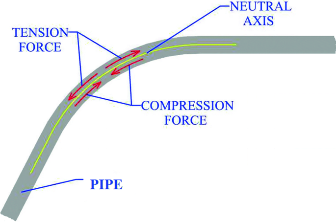
Force distribution in bend area
-
Intrados versus inside radius: The intrados is the zone of compression, bounded by the inside radius and the neutral axis.
-
Extrados versus outside radius: The extrados is the zone of stretching, bounded by the outside radius and the neutral axis.

Types of Pipe Bending
Commonly used pipe bending methods are
-
1.
Rotary die bending.
-
2.
Rollers bending.
-
3.
Hydraulic bending.
-
4.
Incremental bending.
-
5.
Conduit bending.
Above methods are done in either hot bending or cold bending.
Appendix 2: Pipe Benders
3.1 Hydraulic Bender
A hydraulic pipe bender set-up entails of a pressure die, which is connected to the piston of cylinder from which the required pressure is given. The cylinder is filled with hydraulic oil and placed horizontally, with pressure lever at the other end. The pipe is placed perpendicular to the cylinder position, and two supports are placed just beside the pipe at respective ends. The pressure is given in the form of stroke by the lever. For every stroke, the piston will move forward, hence pushing the die until it makes contact with the pipe and to be carried out until the required bend is achieved. The pressure die will push the pipe at the centre, but the two supports will prevent the pipe to move forward along with the die; hence, bending is achieved for different bend radiuses and die can be selected accordingly (Fig. 5).

Hydraulic bender and solid model
3.2 Incremental Bender
This type of bending comes under hot working. In incremental bending, the pipe is fixed in horizontal position. Bender has one fixed support, one movable support and an inductor. Fixed support is stationary with inductor which is used to heat the pipe and pusher which is used to move the pipe for respective bend radius. Pipe is clutched into movable hand jaws and drew onto forcing spine. The position of jaws is determined by demanded bending radius. Tube heater (inductor) is activated and starts heating the bent pipe zone. Turning on a machine drive, the forcing spine is moved, and it is pushing a tube which is now bent around centre of rotation of the moving hand. Bent part of a tube is cooled using water jets (Fig. 6).

Incremental bending parts
Rights and permissions
Copyright information
© 2019 Springer Nature Singapore Pte Ltd.
About this paper

Cite this paper
Karthikeyan, M., Jenarthanan, M.P., Giridharan, R., Anirudh, S.J. (2019). Effects of Wall Thinning Behaviour During Pipe Bending Process—An Experimental Study. In: Chandrasekhar, U., Yang, LJ., Gowthaman, S. (eds) Innovative Design, Analysis and Development Practices in Aerospace and Automotive Engineering (I-DAD 2018). Lecture Notes in Mechanical Engineering. Springer, Singapore. https://doi.org/10.1007/978-981-13-2697-4_35
Download citation
DOI: https://doi.org/10.1007/978-981-13-2697-4_35
Published:
Publisher Name: Springer, Singapore
Print ISBN: 978-981-13-2696-7
Online ISBN: 978-981-13-2697-4
eBook Packages: EngineeringEngineering (R0)