
Abstract
AC generator, transformer and other related high-voltage devices are required to generate, transmit and distribute alternating voltage and current. These pieces of equipment are rated in terms of mega watt (MW) and mega voltage-ampere (MVA). Electrical appliances, such as DVD player, television, microwave oven, light bulb, refrigerator, ceiling fan and many more are rated in terms of watt (W). It requires a careful attention in designing those kinds of equipment to address their power ratings, which in turn address the varying electricity bill. In this case, analysis of AC power plays an important role. This chapter discusses different AC power analytical technique, in terms of instantaneous power , average power, complex power, power factor, maximum power transfer theorem and power factor correction.
Access this chapter
Tax calculation will be finalised at checkout
Purchases are for personal use only
References
C.K. Alexander, M.N.O. Sadiku, Fundamentals of Electric Circuits, 6th edn. (McGraw-Hill Higher Education, Jan 2016)
R.L. Boylestad, Introductory Circuit Analysis, 13th edn. (Pearson, 2016)
J.W. Nilsson, S.A. Riedel, Electric Circuits, 10th edn. (Prentice Hall International Edition, 2015)
H.W. Jackson, Dale Temple, B.E. Kelly, Introduction to Electric Circuits, 9th edn. (Oxford University Press, July 2015)
D. Bell, Fundamentals of Electric Circuits, 7th edn. (Oxford University Press, March 2007)
G. Rizzoni, J. Kearns, Principles and Applications of Electrical Engineering, 6th edn. (McGraw-Hill Education, Oct 2014)
J. David Irwin, R. Mark Nelms, Basic Engineering Circuit Analysis, 11th edn. (Wiley, USA, 2015)
W. Hayt, J. Kemmerly, S. Durbin, Engineering Circuit Analysis, 8th edn. (McGraw-Hill Education, 2012)
M.A. Salam, Basic Electrical Circuits, 2nd edn. (Shroff Publishers & Distributors Pvt. Ltd, India, 2007)
Author information
Authors and Affiliations
Corresponding author
Exercise Problems
Exercise Problems
-
8.1
The excitation voltage and the impedance of a series circuit are given by \(v(t) = 8\sin 10t\;{\text{V}}\) and \(Z = 5\left| \!{\underline {10^{ \circ }}} \right. \;\Omega ,\) respectively. Calculate the instantaneous power.
-
8.2
The excitation current and the impedance of a series circuit are given by \(i(t) = 4\sin (100t\; - 20^{ \circ } ){\text{A}}\) and \(Z = 5\left| \!{\underline {10^{ \circ }}} \right. \;\Omega ,\) respectively. Determine the instantaneous power.
-
8.3
Calculate the average power supplied by the source and the power absorbed by the resistors as shown in Fig. 8.25.
Fig. 8.25 
Circuit for Problem 8.3
-
8.4
Determine the average power supplied by the source and the power absorbed by the resistors shown in Fig. 8.26.
Fig. 8.26 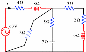
Circuit for Problem 8.4
-
8.5
Calculate the average power supplied by the source and the power absorbed by the resistors as shown in Fig. 8.27.
Fig. 8.27 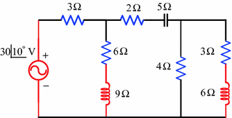
Circuit for Problem 8.5
-
8.6
Determine the average power supplied by the source and the power absorbed by the resistors shown in Fig. 8.28.
Fig. 8.28 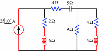
Circuit for Problem 8.6
-
8.7
Find the total average power absorbed by all the resistors in the circuit shown in Fig. 8.29.
Fig. 8.29 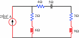
Circuit for Problem 8.7
-
8.8
An industrial load is connected across an alternating voltage source of \(v(t) = 230\sin (314t + 20^{ \circ } )\;{\text{V}}\) that draws a current of \(i(t) = 15\sin (314t + 45^{ \circ } )\;{\text{A}}.\) Determine the apparent power, circuit resistance and capacitance.
-
8.9
The rms values of voltage and current are given by \(V = 20\left| \!{\underline {-15^{ \circ }}} \right. \;{\text{V}},\) and \(I = 3\left| \!{\underline {25^{ \circ }}} \right. \;{\text{A}}.\) Calculate the complex power, real power and reactive power.
-
8.10
The rms values of voltage are given by \(V = 34\left| \!{\underline {25^{ \circ }}} \right. \;{\text{V}}\) and the impedance is \(Z = 6\left| \!{\underline {-15^{ \circ }}} \right. \;\Omega .\) Determine the complex power, real power and reactive power.
-
8.11
A series–parallel circuit is supplied by an rms source of 60 V as shown in Fig. 8.30. Find the complex power for each branch and the total complex power.
Fig. 8.30 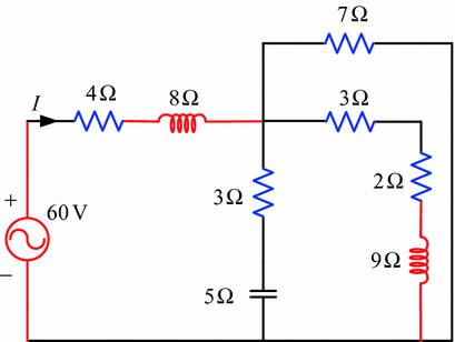
Circuit for Problem 8.11
-
8.12
Calculate the total complex power and complex power of all branches of the circuit shown in Fig. 8.31.
Fig. 8.31 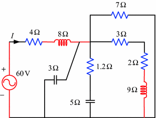
Circuit for Problem 8.12
-
8.13
A 10 kVA, 50 Hz, 0.6 lagging power factor load is connected across an rms voltage source of 220 V as shown in Fig. 8.32. A capacitor is connected across the load to improve the power factor to 0.85 lagging. Find the capacitance of the connected capacitor.
Fig. 8.32 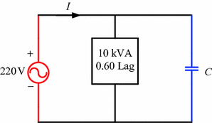
Circuit for Problem 8.13
-
8.14
Two loads with different power factor are connected with the source through a transmission line as shown in Fig. 8.33. Determine the source current and the source voltage.
Fig. 8.33 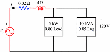
Circuit for Problem 8.14
-
8.15
A voltage source delivers power to the three loads shown in Fig. 8.34. Find the source current and the source voltage.
Fig. 8.34 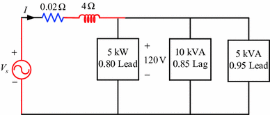
Circuit for Problem 8.15
-
8.16
A load absorbs maximum power from the circuit shown in Fig. 8.35. Determine the load impedance and the maximum power.
Fig. 8.35 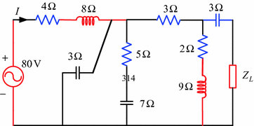
Circuit for Problem 8.16
-
8.17
A load absorbs maximum power from the circuit shown in Fig. 8.36. Calculate the load impedance and the maximum power.
Fig. 8.36 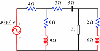
Circuit for Problem 8.17


Rights and permissions
Copyright information
© 2018 Springer Nature Singapore Pte Ltd.
About this chapter

Cite this chapter
Salam, M.A., Rahman, Q.M. (2018). AC Power Analysis. In: Fundamentals of Electrical Circuit Analysis. Springer, Singapore. https://doi.org/10.1007/978-981-10-8624-3_8
Download citation
DOI: https://doi.org/10.1007/978-981-10-8624-3_8
Published:
Publisher Name: Springer, Singapore
Print ISBN: 978-981-10-8623-6
Online ISBN: 978-981-10-8624-3
eBook Packages: EngineeringEngineering (R0)