
Abstract
Electrical laws are necessary to analyse any electrical circuit effectively and efficiently by determining different circuit parameters such as current, voltage power and resistance. These laws include Ohms law, Kirchhoff’s current and voltage laws, and voltage and current division rules. The knowledge of series and parallel circuit orientations, delta–wye and wye–delta–wye transformations are also required to analyse electrical circuits. In this chapter, different electrical laws, delta–wye and wye–delta–wye transformations, source conversion technique and Wheatstone bridge circuit have been discussed.
Access this chapter
Tax calculation will be finalised at checkout
Purchases are for personal use only
References
C.K. Alexander, M.N.O. Sadiku, Fundamentals of Electric Circuits, 6th Edn, (McGraw-Hill Higher Education, New York, January 2016)
R.L. Boylestad, Introductory Circuit Analysis, vol. 13 (Pearson, London, 2016)
J. David Irwin, R. Mark Nelms, Basic Engineering Circuit Analysis, 11th edn. (Wiley, USA, 2015)
J.W. Nilsson, S.A. Riedel, Electric Circuits, vol. 10 (Prentice Hall International Edition, New Jersey, 2015)
Md. Abdus Salam, Basic Electrical Circuits, 2nd edn. (Shroff Publishers & Distributors Pvt. Ltd, India, 2007)
Author information
Authors and Affiliations
Corresponding author
Exercise Problems
Exercise Problems
-
2.1
A 750 W electric iron is connected to a 220 V voltage source. Determine the current drawn by the iron.
-
2.2
A \(15\,\Omega\) resistor is connected to a 240 V voltage source. Calculate the power absorbed by the resistor.
-
2.3
A circuit with different branches along with currents is shown in Fig. 2.50. Determine the values of the unknown currents.
Fig. 2.50 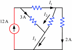
Circuit for Problem 2.3
-
2.4
Figure 2.51 shows a circuit with some unknown currents. Determine the unknown currents.
Fig. 2.51 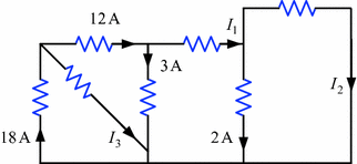
Circuit for Problem 2.4
-
2.5
Some known and unknown voltages of a circuit are shown in Fig. 2.52. Use KVL to determine the unknown voltages.
Fig. 2.52 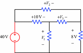
Circuit for Problem 2.5
-
2.6
Figure 2.53 shows a circuit with known and unknown voltages. Use KVL to find the voltages \(V_{1}\) and \(V_{2}\).
Fig. 2.53 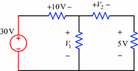
Circuit for Problem 2.6
-
2.7
A voltage-controlled voltage source is shown in Fig. 2.54. Use KVL to determine the voltage \(V_{x}\) and the voltage between the points (nodes) a and b.
Fig. 2.54 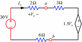
Circuit for Problem 2.7
-
2.8
A current-controlled voltage source is shown in Fig. 2.55. Determine the currents \(I_{s}\) and \(I_{x}\) using KVL.
Fig. 2.55 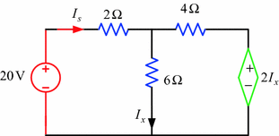
Circuit for Problem 2.8
-
2.9
A voltage-controlled current source is shown in Fig. 2.56. Calculate the voltage drop across the \(4\,\Omega\) resistor.
Fig. 2.56 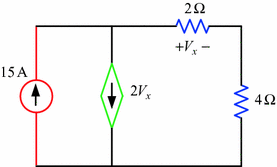
Circuit for Problem 2.9
-
2.10
Figure 2.57 shows a current-controlled current source. Use KCL to determine the power absorbed by the \(8\,\Omega\) resistor.
Fig. 2.57 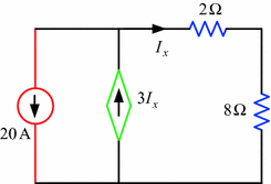
Circuit for Problem 2.10
-
2.11
A series–parallel circuit with a voltage source is shown in Fig. 2.58. Calculate the total circuit resistance and the source current.
Fig. 2.58 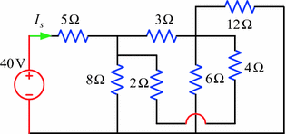
Circuit for Problem 2.11
-
2.12
Figure 2.59 shows a series–parallel circuit with a voltage source. Calculate the total circuit resistance and the source current.
Fig. 2.59 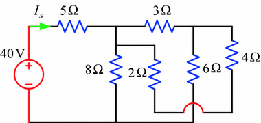
Circuit for Problem 2.12
-
2.13
A series–parallel circuit with a voltage source is shown in Fig. 2.60. Determine the total circuit resistance and the source current.
Fig. 2.60 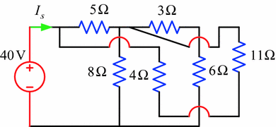
Circuit for Problem 2.13
-
2.14
A series–parallel circuit is shown in Fig. 2.61. Calculate the total circuit resistance and the power absorbed by the \(4\,\Omega\) resistor.
Fig. 2.61 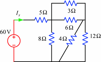
Circuit for Problem 2.14
-
2.15
Find the current through the \(4\,\Omega\) resistor of the circuit shown in Fig. 2.62.
Fig. 2.62 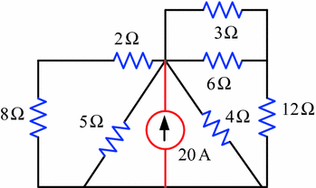
Circuit for Problem 2.15
-
2.16
A series–parallel circuit is shown in Fig. 2.63. Calculate the source current and the voltage drop across the \(4\,\Omega\) resistor.
Fig. 2.63 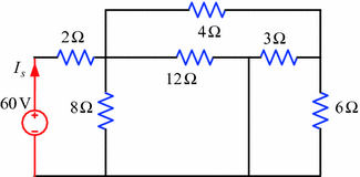
Circuit for Problem 2.16
-
2.17
Figure 2.64 shows a series–parallel circuit. Determine the source current and the voltage drop across the \(8\,\Omega\) resistor.
Fig. 2.64 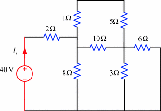
Circuit for Problem 2.17
-
2.18
Figure 2.65 shows a series–parallel circuit. Find the total circuit resistance and the source current.
Fig. 2.65 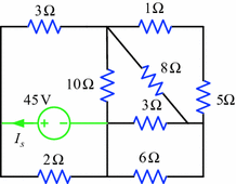
Circuit for Problem 2.18
-
2.19
A series–parallel circuit is shown in Fig. 2.66. Calculate the total circuit resistance and the source current.
Fig. 2.66 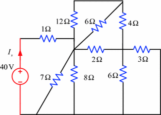
Circuit for Problem 2.19
-
2.20
Figure 2.67 shows a series–parallel circuit. Calculate the total circuit resistance and the source current.
Fig. 2.67 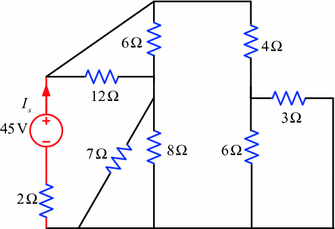
Circuit for Problem 2.20
-
2.21
A series–parallel electrical circuit is shown in Fig. 2.68. Find the total circuit resistance and the source current.
Fig. 2.68 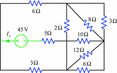
Circuit for Problem 2.21
-
2.22
Figure 2.69 shows a series–parallel electrical circuit. Calculate the total circuit resistance and the source current.
Fig. 2.69 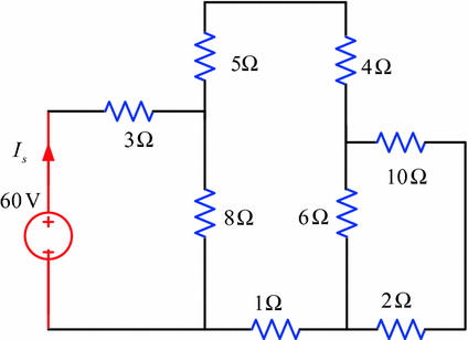
Circuit for Problem 2.22
-
2.23
A series–parallel circuit is shown in Fig. 2.70. Determine the total circuit resistance and the source current.
Fig. 2.70 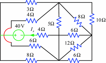
Circuit for Problem 2.23
-
2.24
A series–parallel circuit is shown in Fig. 2.71. Calculate the total circuit resistance and the source current.
Fig. 2.71 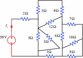
Circuit for Problem 2.24
-
2.25
An electrical circuit is shown in Fig. 2.72. Determine the total circuit resistance and the power absorbed by the \(2\,\Omega\) resistor.
Fig. 2.72 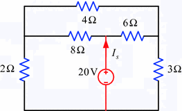
Circuit for Problem 2.25
-
2.26
Figure 2.73 shows an electrical circuit. Calculate the total circuit resistance and the current through the \(5\,\Omega\) resistor.
Fig. 2.73 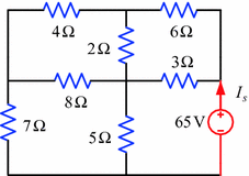
Circuit for Problem 2.26
-
2.27
An electrical circuit is shown in Fig. 2.74. Calculate the total circuit resistance and the source current in the circuit.
Fig. 2.74 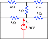
Circuit for Problem 2.27
-
2.28
A delta–wye-connected electrical circuit is shown in Fig. 2.75. Determine the total circuit resistance, source current and the voltage drop across the \(3\,\Omega\) resistor.
Fig. 2.75 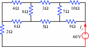
Circuit for Problem 2.28
-
2.29
An electrical circuit is shown in Fig. 2.76. Use delta–wye conversion to determine the total circuit resistance and the source current in the circuit.
Fig. 2.76 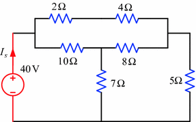
Circuit for Problem 2.29
-
2.30
A series–parallel electrical circuit is shown in Fig. 2.77. Calculate the power absorbed by the \(4\,\Omega\) resistor.
Fig. 2.77 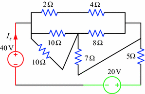
Circuit for Problem 2.30
-
2.31
Figure 2.78 shows a series–parallel electrical circuit. Calculate the current in the \(4\,\Omega\) resistor.
Fig. 2.78 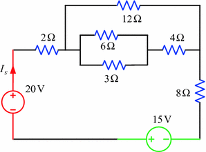
Circuit for Problem 2.31
-
2.32
Figure 2.79 shows a series–parallel electrical circuit. Calculate the value of the voltage \(V_{x}\).
Fig. 2.79 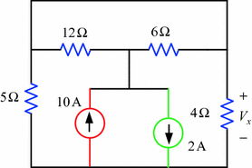
Circuit for Problem 2.32
-
2.33
A series–parallel electrical circuit with two current sources is shown in Fig. 2.80. Determine the current in the \(5\,\Omega\) resistor.
Fig. 2.80 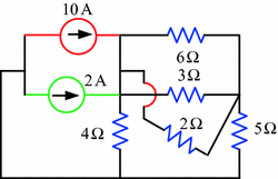
Circuit for Problem 2.33
-
2.34
A series–parallel electrical circuit is shown in Fig. 2.81. Calculate the voltage drop across the \(4\,\Omega\) resistor.
Fig. 2.81 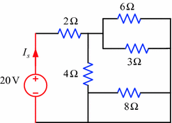
Circuit for Problem 2.34
-
2.35
Figure 2.82 shows a series–parallel electrical circuit. Determine the power absorbed by the \(10\,\Omega\) resistor.
Fig. 2.82 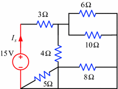
Circuit for Problem 2.35
-
2.36
Figure 2.83 shows a series–parallel electrical circuit. Determine the value of the voltage, \(V_{x}\).
Fig. 2.83 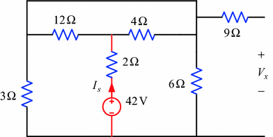
Circuit for Problem 2.36
-
2.37
Calculate the value of the voltage, \(V_{0}\) of the circuit as shown in Fig. 2.84.
Fig. 2.84 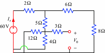
Circuit for Problem 2.37
-
2.38
An electrical circuit is shown in Fig. 2.85. Calculate the voltage, \(V_{0}\), of the circuit.
Fig. 2.85 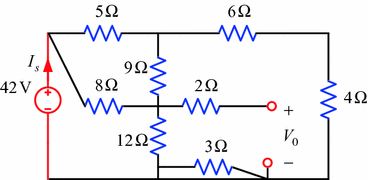
Circuit for Problem 2.38
-
2.39
An electrical circuit is shown in Fig. 2.86. Determine the voltage, \(V_{0}\), of the circuit.
Fig. 2.86 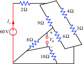
Circuit for Problem 2.39
-
2.40
Figure 2.87 shows an electrical circuit. Calculate the voltage, \(V_{0}\), of the circuit.
Fig. 2.87 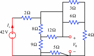
Circuit for Problem 2.40
-
2.41
An electrical circuit is shown in Fig. 2.88. Find the voltage, \(V_{0}\), of the circuit.
Fig. 2.88 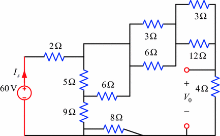
Circuit for Problem 2.41
-
2.42
An electrical circuit is shown in Fig. 2.89. Determine the voltage, \(V_{0}\), of the circuit.
Fig. 2.89 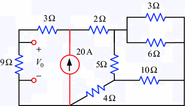
Circuit for Problem 2.42
-
2.43
An electrical circuit is shown in Fig. 2.90. Calculate the voltage, \(V_{0}\), of the circuit.
Fig. 2.90 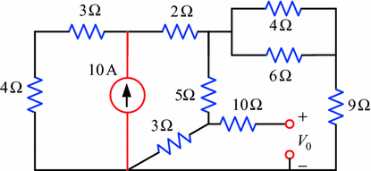
Circuit for Problem 2.43
-
2.44
Figure 2.91 shows an electrical circuit. Determine the voltage, \(V_{x}\), of the circuit.
Fig. 2.91 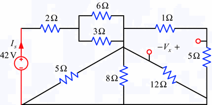
Circuit for Problem 2.44
-
2.45
An electrical circuit is shown in Fig. 2.92. Calculate the voltage, \(V_{0}\), of the circuit.
Fig. 2.92 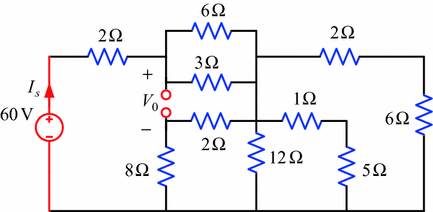
Circuit for Problem 2.45
-
2.46
Figure 2.93 shows an electrical circuit. Find the voltage, \(V_{0}\), of the circuit.
Fig. 2.93 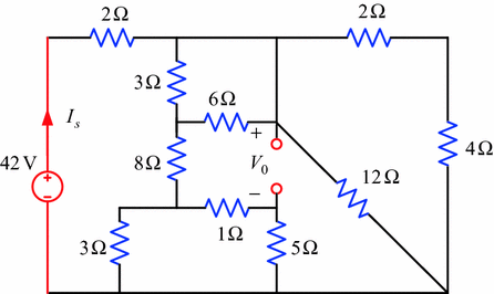
Circuit for Problem 2.46
-
2.47
Figure 2.94 shows an electrical circuit. Calculate the voltage, \(V_{0}\), of the circuit.
Fig. 2.94 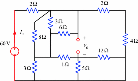
Circuit for Problem 2.47
-
2.48
An electrical circuit is shown in Fig. 2.95. Use source conversion technique to calculate the voltage drop across the \(5\,\Omega\) resistor.
Fig. 2.95 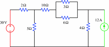
Circuit for Problem 2.48
-
2.49
Figure 2.96 shows an electrical circuit. Determine the voltage drop across the \(2\,\Omega\) resistor by using source conversion technique.
Fig. 2.96 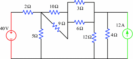
Circuit for Problem 2.49
-
2.50
Use source conversion technique to find the voltage drop across the \(3\,\Omega\) resistor of the circuit in Fig. 2.97.
Fig. 2.97 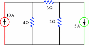
Circuit for Problem 2.50


Rights and permissions
Copyright information
© 2018 Springer Nature Singapore Pte Ltd.
About this chapter

Cite this chapter
Salam, M.A., Rahman, Q.M. (2018). Electrical Laws. In: Fundamentals of Electrical Circuit Analysis. Springer, Singapore. https://doi.org/10.1007/978-981-10-8624-3_2
Download citation
DOI: https://doi.org/10.1007/978-981-10-8624-3_2
Published:
Publisher Name: Springer, Singapore
Print ISBN: 978-981-10-8623-6
Online ISBN: 978-981-10-8624-3
eBook Packages: EngineeringEngineering (R0)