
Abstract
According to “Law of the People’s Republic of China on the Prevention and Control of Infectious Diseases” issued on December 1st in 2004, infectious diseases can be classified as the first class, the second class and the third class.
You have full access to this open access chapter, Download chapter PDF
Keywords
- Severe Acute Respiratory Syndrome
- Polluted Area
- Severe Acute Respiratory Syndrome
- Infectious Disease Hospital
- Isolation Ward
These keywords were added by machine and not by the authors. This process is experimental and the keywords may be updated as the learning algorithm improves.
7.1 Classification
7.1.1 Classification of Infectious Diseases
According to “Law of the People’s Republic of China on the Prevention and Control of Infectious Diseases” issued on December 1st in 2004, infectious diseases can be classified as the first class, the second class and the third class.
Infectious diseases in the first class include the plague and the cholera.
Infectious diseases in the second class include the severe acute respiratory syndrome (SARS), the human immunodeficiency virus (HIV), the viral hepatitis, the poliovirus, the human avian influenza, the measles, the Epidemic Hemorrhagic Fever, the rabies virus, the Japanese Encephalitis Virus, the dengue virus, the colletotrichum gloeosporioides, the bacillary and amoebic dysentery, the pulmonary tuberculosis, the typhoid and paratyphoid fever, the epidemic cerebrospinal meningitis, the pertussis, the diphtheria, the neonatal tetanus, the scarlet fever, the brucellosis, the gonorrhea, the syphilis, the leptospirosis, the schistosomiasis, and the malaria.
Infectious diseases in the third class include the influenza, the epidemic mumps, the rubella, the Acute Hemorrhagic Conjunctivitis, the leprosy, the epidemic and local typhus, the leishmaniasis, the echinococcosis, the filariasis, and the infectious diarrhea which is not caused by the cholera, the bacillary and amoebic dysentery, and the typhoid and paratyphoid fever.
It is also specified in this law that the preventive control measures with the first-class infectious diseases should be applied for those infectious diseases in the second class, including SARS, the pulmonary anthrax and the human avian influenza. For the infectious diseases in the second class and those with unknown origin, which need the preventive control measures with the first-class infectious diseases, it must be approved, published and implemented by the state council after the epidemic incidence is reported immediately by the health administrative department of the state council.
Now more attention has been paid on the Ebola virus.
7.1.2 Classification of Isolation Wards
-
1.
Isolation ward can be classified as the infectious isolation ward and the protective isolation ward (the isolation ward for curing the mental disease is not included in this book).
The infectious isolation ward is also termed as the negative pressure isolation ward. It is mainly used for prevention of the airborne disease from infecting both the environment outside the ward and the people except for the patient. These diseases include the tuberculosis, the chickenpox, the pneumonia, SARS, the hemorrhagic fever virus, etc.
This book focuses on the negative pressure isolation ward only.
Some infected patients may also need protection, such as tuberculosis patients.
In occasions when there is no infectious patient inside, the isolation ward can be used as the ordinary ward. This has been clearly specified in the standard of some nations, such as the AIA standard in U.S.A. “When there is no need for isolation, the isolation ward can be used as the ordinary nursing room or can be divided into individual isolation wards.” “When there is not patients with airborne diseases, the isolation ward can be used for patients without infectious diseases” [1].
-
2.
The infectious strength of the disease on patient inside the infectious isolation ward can be classified as four levels which can be referred in Chap. 1.
The function of the isolation ward is as follows:
-
(1)
The isolation ward should play the role of isolation.
Isolate the ward from the ambient environment, and isolate the patient from the medical personnel.
-
(2)
The isolation ward should play the role of safety.
To guarantee the safety of the environment outside the ward.
To guarantee the safety of the medical personnel inside the ward.
It could also be classified as four levels according to the required pressure difference, such as the Australian standard which is shown in Table 7.1 [2].
Table 7.1 Classification of isolation ward in “Guidelines for the classification and design of isolation rooms in health care facilities” from Australia
-
(1)
7.2 Layout Plan
7.2.1 Environment
-
1.
The distance between the isolation ward and the surrounding buildings especially the dormitories and the public buildings should be 20 m at least [3].
This has been pointed out for the site selection of the infectious diseases hospital in the national standard GB50849-2014 “Code for design of infectious diseases hospital”. Since the isolation ward is the main component of hospital, this principle should be followed naturally. The concept of the minimum distance 20 m was first proposed by author, which was adopted by the national standard GB 50346-2004 “Architectural and technical code for biosafety laboratories”. This is aimed in terms of the risk of the exhaust air from the biosafety laboratories. When the microbes with highly pathogenic and the safety of the exhaust air are concerned, the isolation ward should not be an exceptional.
-
2.
In the general hospital, it is better if the isolation ward can be placed alone. Otherwise it should be set at one edge of the building as possible. If should form a zone and placed at the leeward wind side in the most annual wind direction in this area. When there are two most wind directions in this area, the isolation ward should be placed at the opposite direction facing the wind direction with the least frequency.
7.2.2 Partition
-
1.
For the ward are consisting of multiple isolation wards, the clean area, the potentially polluted area and the polluted area should be strictly distinguished.
In general, the ward itself (including its bathroom) and the area for activity of patients are the polluted area. The public corridor is the potentially polluted area. The primary changing room, the preparatory room and the offices for the medical personnel area the clean area.
-
2.
If there is enough space for setting double corridors, the patient should enter into the ward through the back corridor and the back door. In this case, the back corridor should be classified as the polluted area. The relative pressure inside the back corridor is positive. The net width of the corridor should be not less than 2.4 m. When there is relative height difference in the corridor, the barrier-free cohesion edge should be used, and the antiskid measures should be taken.
The medical personnel should enter into the ward through the front corridor which should be classified as the potentially polluted area. Only the region outside the exit of this corridor could be classified as the clean area.
Figure 7.1 shows the renovated SARS ward in a hospital in Shanghai, where the scheme with two corridors was adopted [2]. In the figure, the semi-clean area can be considered as the potentially polluted area. While the semi-polluted area can also be considered as the polluted area, where the pressure is slightly higher than that in the ward. Besides, buffer rooms should be set at two edges of this corridor.
Fig. 7.1 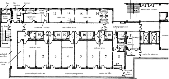
Layout of the renovated SARS ward. 1–7 Ward; 8 Analysis laboratory; 9 Buffer room; 10 Bathroom; 11 Disinfection room; 12 Delivery window; 13–15 Offices for the director, the doctor and the nurse, respectively; 16 Treatment room
As shown in Fig. 7.1, it is better if there is also the buffer room at the back door of the ward. In this case, it is unnecessary to set the buffer room at two edges of the exterior corridor which can be classified as the potentially polluted area.
-
3.
In the national standard GB50849-2014 “Code for design of infectious diseases hospital”, more than two passageways should be set for the ward in the hospital where the number of the sickbeds is more than 150, and two passageways are required to be set for the ward in the hospital where the number of the sickbeds is less than 150. The detailed information is given in Table 7.2 (Both Tables 7.2 and 7.3 are cited from the literature “Discussion on planning design of the infectious diseases hospital” by Zhang Chun-yang and Huang Kai-xin). The items 2 and 3 in the table are united.
Table 7.2 Setting of streamline and general passageway in the infectious diseases hospital Table 7.3 Setting of the ward and the outpatient room (or the emergency room) If the ward is placed in other buildings, the passageway must be set independently, which could be disinfected in a closed space.
-
4.
According to the different transmission routes of the infectious diseases, the ward and the outpatient room (or the emergency room) in the hospital are set. The ward with infectious disease by airborne transmission must be set independently, which is shown in Table 7.3.

7.3 Isolation Ward
7.3.1 Ward
-
1.
The isolation wards can be classified as single room, double room and multiple room. In the local standard DB 11/663-2009 “Essential construction requirements of negative pressure isolation ward” was issued in Beijing (which is shortened as “Essential requirements”), it is required that the maximum number of occupants is three. While in standards from Germany and U.S.A., it is required that the maximum number of occupants in each ward is two, and for the renovated ward the corresponding value is four.
Table 7.4 shows the data on the area of the ward by “Essential requirements” and standard from U.S.A.
In hospitals from the Netherlands, the width of the sickbed is 1 m, and the minimum distance between sickbeds is 1.5 m. In U.S.A., the distance between sickbed is required 2.24 m.
In short, the space inside the ward should be spacious enough to place equipments such as the bedside X-ray machine and the breathing machine. Therefore, the values of the distances are larger than that in the ordinary ward.
According to “Essential requirements”, the net height of the ward should not be less than 2.8 m.
7.3.2 Accessory Rooms
-
1.
Except for the isolation, the intensive care unit, the office for doctor, the office for nurse, the nurse station, the disposal room, the treatment room, the duty room, the base for bed and cloth, the canteen preparation room and the room for boiling water should also be placed inside the ward area. When the number of the wards is large, X-ray room should be set. When there is the teaching task, the demonstration classroom should be set.
-
2.
The bathroom should be annexed in the isolation ward, which includes the closet bowel flushed with sterilized water, the shower, the washbasin with inductive tap. Door should not be placed for other bathrooms outside of the ward. Instead, the open labyrinth-style inlet can be adopted.
-
3.
The canteen preparation room in each ward area should distinguish the clean room from the polluted room. The delivery window is set between them. If the disposable tableware is used, the canteen preparation room can be set inside the clean area, and no isolation is needed.
-
4.
If needed, biosafety cabinet should be set for testing of special specimens, which is operated inside the Class 2 biosafety laboratory.
-
5.
The autopsy room for the infected patients especially those with the severe acute respiratory syndrome (SARS) should be designed according to Class 3 biosafety laboratory. According to the Japanese standard, the anatomy station should be placed inside the unidirectional flow unit.
7.3.3 People Flow and Goods Flow
-
1.
Delivery window should be placed on the wall of the corridor adjacent to the isolation ward, which is used for deliver the medicine and the food. According to the nation standard JG/T 382-2012 “Pass box”, the classification of the delivery window is shown in Table 7.5. The delivery window set between the isolation ward and the polluted area should be Type B1 or C1. Figure 7.2 shows the basic appearance of the delivery window.
Table 7.5 Classification of the delivery window Fig. 7.2 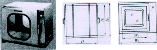
Basic and ordinary delivery window
-
2.
Air shower should not be placed along the passage of people flow. Air curtain should not be used at the gate in the ward area.
-
3.
The ordinary vertical hinged door or the upper suspended sliding door can be used between the isolation ward and the buffer room. The vertical hinged door is suitable to be set between the buffer room and the corridor. In both cases, the wooden door should not be used.
-
4.
When it is possible, the advantage is more obvious if the sliding door is adopted between the isolation ward and the buffer room. In this case, the velocity of the induced turbulence by the sliding door is the minimum, compared with that of the vertical hinged door. Therefore, the sliding door is recommended for the entrance of the isolation ward in related standards in Japan. This is also recommended in AIA standard in U.S.A. and it is also pointed out that the sliding slot should not be set on the floor for this kind of the sliding door. Therefore the upper suspected sliding door should be used, which is the same as that of the clean operating room. Of course, whether the sliding door can be set depends on the space of the buffer room. The gap of the vertical hinged door is small, so it should be used between the buffer room and the corridor, which is suggested in Japanese standard.
-
5.
It is not necessary to use the air-tight door and the air-tight inter-lock door for the doors of the isolation ward and the buffer room. The requirement can be met when the ordinary door is used. But the wooden door should not be used.
-
6.
Except for the safety door and the door towards the entrance hall which open outwardly, other doors should open towards the side with larger pressure.
-
7.
Door should not be placed for other bathrooms outside of the ward. Instead, the open labyrinth-style inlet used in the airport terminal building can be adopted.
-
8.
Buffer room is placed outside of the isolation ward. Positive pressure is maintained in the buffer room relative the isolation ward, while negative pressure or zero pressure is kept in buffer room relative to the outside of the buffer room. This kind is called Three-Room-One-Buffer, or Two-Area-One-Buffer, which is shown in Fig. 3.4.
The isolation ward is the polluted area, while the area outside of the corridor is the clean area.

7.4 Clean Air Conditioner
7.4.1 Particularity of Cleaning Air Conditioner for Isolation Ward
-
1.
There was objection opinion for the usage of air conditioning system in the isolation ward during the early epidemic of SARS in China. Because of the incognizance of SARS, for the purpose of the emergency response, it was emphasized in the “Design Highlights for Hospital Buildings Receiving SARS Infected Patients” issued by the Ministry of Health of the People’s Republic of China that the ventilation condition is accessible to all the areas. Central air conditioning system is prohibited in all the areas. Air exhaust unit can be installed for the simple-built negative pressure ward.
It is understandable that these provisional measures were specified. But during the East Asia Rainy Season (or Meiyu Season) and the hot summer in the southern region where the humidity is extremely large, the propagation of pathogenic microbes indoors cannot be prevented in hospitals by natural ventilation alone. In this case, the microbial contamination may still occur. If the temperature and the humidity indoors are very high, the patient will generate heat and sweat, which will increase the bacterial generation rate. When the medical personnel wear the insulation garment, the protective cloth, the mask and eyeglasses, sweating will occur soon after the work. Sometimes febrile disease may even appear. Especially in the isolation ward for SARS, the working environment will be worsened if the problem of HVAC and environmental control is not solved. This will influence the physical and mental health of the medical personnel.
In June of 2003, the WHO representative office in China wrote to Ministry of Health of China. Different opinion was proposed. Natural ventilation by window opening is not allowed in the isolation ward for SARS. The HVAC system should be operated continuously. Exhaust air fan should be installed on the exterior window or the exterior wall, so that negative pressure is maintained indoors.
However, the “Hospital infection control guidance for Severe Acute Respiratory Syndrome (SARS)” issued by WHO pointed out that when there is no independent air exhaust system in HVAC system, the air conditioning system can be turned off, and ventilation can be provided by window opening. But windows are prohibited to be open towards the public space.
In fact, air conditioning system is not prohibited in related foreign standards. And circulation air can be adopted conditionally.
In “Guidelines for Preventing the Transmission of Mycobacterium tuberculosis in Health-Care Facilities” issued by CDC from U.S.A. in 1994, it was emphasized that for the known airborne infectious droplet nuclei, the general exhaust system can be adopted. Meanwhile, it was pointed out that it was inevitable to adopt the scheme of recirculation air. When HEPA filter is used, air can be re-circulated. Three kinds of air distribution were proposed, which would be introduced in the next section. It was also pointed out in “The guideline of design and management for air-conditioning system of Hospital” by Healthcare Engineering Association of Japan that the fan unit with HEPA filter can be installed in the isolation ward.
In March 1st of 2003, novel idea for central air conditioning system appeared in “Code for hygiene of central air-conditioning ventilation system in public places” published by ministry of health of China. It was specified that when the epidemic of airborne disease occurs in the local area, the central air conditioning system can be operated continuously only when the following requirements are satisfied. It can be used when the full fresh air scheme is used. It can also be used when the air cleaning device with disinfection function is installed and its performance is guaranteed to be effective. It can also be used when independent ventilation is accessible to each room when the HVAC system scheme by the combination of the fan coil unit and the outdoor air is adopted. However, this solution is obviously not enough. It should be pointed out that for the isolation ward with infectious disease, except for the full fresh air system, air can be circulated only when HEPA filter is installed (at the return air grille). Of course, no matter whether full fresh air system is used, exhaust air must pass through HEPA filter.
For the infectious diseases hospital and isolation ward, the above idea is also applicable.
But different cleaning air conditioner system should be set for the clean area, the potentially polluted area and the polluted area, respectively.
-
2.
The air-circulation system is only suitable for the single ward with infectious disease. Or circulation of indoor air is adopted for the ward receiving multiple people with the same kind of disease. When heating and cooling are provided by fan coil unit, another independent or public outdoor air supply system should be set. In this case, it is suitable to switch to or adopt the full fresh air system for one or more wards.
7.4.2 Specific Requirement
-
1.
The air change rate in the isolation ward should be 8–12 h−1. The flow rate of outdoor air per person should not be less than 40 m3/h. In other auxiliary rooms, the air change rate should be 6–10 h−1.
-
2.
Although there is no requirement on the air cleanliness level in the isolation ward, air filtration device with low pressure drop and efficiency larger than the high and medium efficiency air filter shown in Table 3.20(1), (2) must be installed at the air supply opening. HEPA filter should be installed for the supplied air into the buffer room where the air change rate is ≥60 h−1.
-
3.
The safely demountable leakage-free high efficiency negative pressure air exhaust device sealed with dynamic air current can be used in the isolation ward and its bathroom.
-
4.
The outlet of the air exhaust pipeline should be linked towards outdoors. The check valve and the rain droplet prevention measures should be used. The end of the air exhaust pipeline should be above the roof by more than 2 m. It should be far away from the air intake opening on the wall by more than 20 m, and it should be located in the downstream of the air intake opening. When the distance between them is less than 20 m, the retaining fence should be set.
-
5.
The cleaning air conditioning system should be operated for 24 h continuously. The air velocity of the supplied air in the daytime should not be less than 0.13 m/s. While in the evening, the flow rate is under the low gear station, and the velocity of the supplied air should not be larger than 0.15 m/s. The air supply and air exhaust should be inter-locked. The air exhaust system should be turned on at first and closed later.
-
6.
In the ordinary time, the cleaning air conditioning system can provide normal pressure status in the isolation ward, when the non-infectious patients are received. But the pressure conversion scheme is not allowed in the infectious isolation ward and the protective isolation ward. This has also been specified in the related standards in Japan and U.S.A.
-
7.
In the isolation ward where cleaning air conditioning system and air circulation system with HEPA filter are used, indoor air cleaning device should not be used again to disturb the original air distribution.
-
8.
Air cleaning device must be installed at the entrance of the outdoor air. According to national standard GB51039-2014 “Code for design of general hospital”, two-stage air filters including the coarse and fine filters should be installed at least for the entrance of the outdoor air, when the annual concentration of respirable particulate matter PM10 in the atmosphere does not exceed 0.10 mg/m3. When it exceeds 0.10 mg/m3, the high and medium efficiency air filter should be added.
In European standard EN13779, it is also specified that when the outdoor air is clean, two-stage air filters such as F5 + F7 should be set for the outdoor air pipeline.
It is also specified in ISO 16814 that G4 + F7 should be set for outdoor air. It is better to set F5 + F8. It is very good to set F7 + F9.
-
9.
According to GB51039-2014 “Code for design of general hospital”, for the return air grille in the HVAC system in the auxiliary room for isolation ward area, air filters with initial pressure drop less than 50 Pa, the one-pass penetration for microbes not larger than 10% and the one-pass arrestance for particles not larger than 5% should be installed.
7.5 Positioning Arrangement of Air Openings
7.5.1 Arrangement for Single Bed
-
1.
The air distribution scheme with upper-supply and lower-return should be adopted in negative pressure isolation ward. The total trend of airflow should be consistent with the settlement direction of particles. The airflow inside the negative pressure ward and its ward area should be directional, which flows from the clean area towards the polluted area.
-
2.
According to the simulated and experimental results in Chap. 4, the primary and secondary air supply outlets as shown in Fig. 7.3 should be chosen for the negative pressure isolation ward. The primary air supply outlet is set on the ceiling above where the medical personnel usually stand near the sickbed. The distance from the head of the sickbed should not be larger than 0.5 m. The length should not be less than 0.9 m. The secondary air supply outlet should be set on the ceiling above the end of the sickbed. The distance from the end of the sickbed should not be larger than 0.3 m. The length should not be less than 0.9 m.
Fig. 7.3 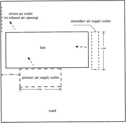
Location and dimension of air supply outlets indoors
-
3.
The ratio of the areas between the primary and the secondary air supply outlets should be between 2:1 and 3:1. The velocity of supplied air should not be less than 0.13 m/s.
-
4.
The type of double louver grille should be used for air supply outlets.
-
5.
The type of single louver grille should be used for air return (or exhaust) opening. They should be placed at the lower side of the head of the sickbed relative to the air supply outlet. The upper edge of the air return (or exhaust) openings should be placed less than 0.6 m above the floor. The lower edge should be higher than 0.1 m above the floor. The velocity of the return air (or exhaust air) should not be larger than 1.5 m/s.

7.5.2 Arrangement for Multiple Beds
-
1.
The layout of the air supply outlets for double beds can be chosen as shown in Figs. 7.4 and 7.5.
Fig. 7.4 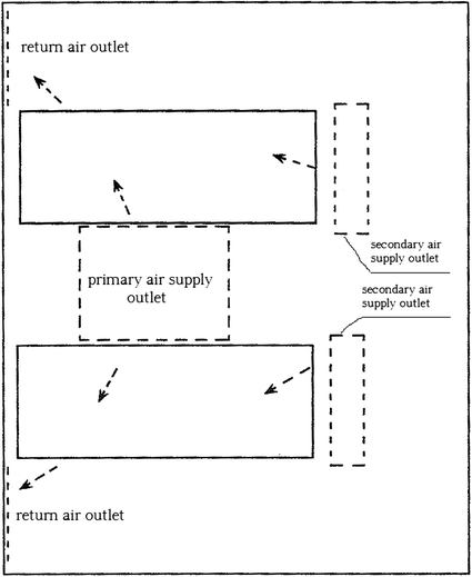
Scheme one for air supply outlets in double-bed ward
Fig. 7.5 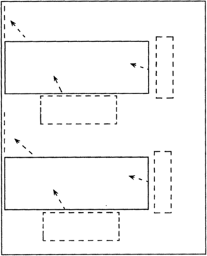
Scheme two for air supply outlets in double-bed ward
-
2.
The layout of the air supply outlets for multiple beds can be chosen as shown in Fig. 7.6.
Fig. 7.6 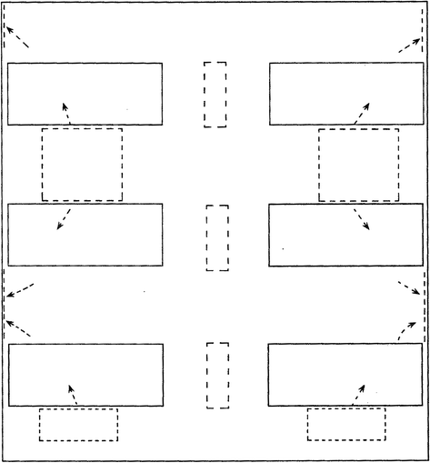
Scheme two for air supply outlets in multiple-bed ward
For the ward with multiple beds, it is not allowed that one bed is located at the leeward side of another ward. Figure 7.7 shows an example where infection occurred in practice. Airflow from natural ventilation or mechanical ventilation moves from one side of the room (at the window side) towards the door side (or the bathroom). This results in infection at the leeward side.
Fig. 7.7 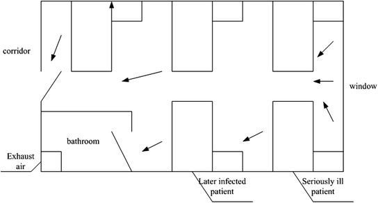
Example of the layout of sickbeds infected at the leeward side


7.5.3 Arrangement of Air Openings in Buffer Room
-
1.
When the temperature inside the ward is higher than that in the buffer room, the air return (or exhaust) openings inside the buffer room should be placed on the ceiling above the door connecting the ward. Air supply outlet should be placed on the ceiling at the opposite side relative to the air return (or exhaust) openings. They are not necessarily symmetric. Based on the analysis on the function of temperature difference in Chap. 6, when the door of the ward is open under this condition, the convection of air with air out above and air entrance down will appear. The air return opening above the door of the buffer room can remove the pollutant from the airflow leaving the ward immediately, which is shown in Fig. 7.8.
Fig. 7.8 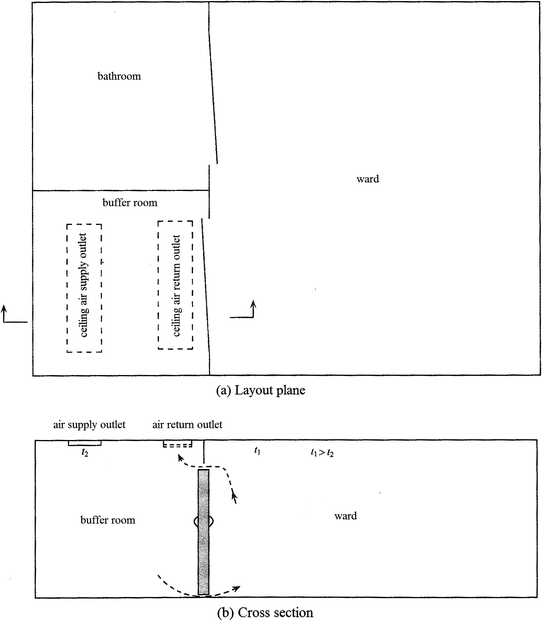
Layout of the air openings in the buffer room (When the temperature inside the ward is higher than that in the buffer room, the door of the buffer room towards outside is not given in the figure.)
-
2.
If the temperature inside the buffer room is higher than that in the ward, the air distribution with the upper-supply and lower-return scheme can be adopted inside the buffer room. This is because when the door of the ward is open, the polluted air will penetrate into the buffer room from the lower part of the door.

7.6 Determination of Pressure Difference and Differential Pressure Flow Rate
7.6.1 Pressure Difference
-
1.
Based on the analysis on the dynamic isolation technique and DB11/663-2009 “Essential construction requirements of negative pressure isolation wards”, the distribution of the pressure difference of the isolation wards can be set as shown in Fig. 7.8.
The relative pressure between the ward and the buffer room, as well as that between the buffer room and the interior corridor, should not be less than 5 Pa. The sequence for the extent of negative pressure is the bathroom, the negative pressure isolation ward, the buffer room, and the interior corridor. For the ordinary negative pressure isolation ward, at least one buffer room should be set outside the ward based on the actual condition.
-
2.
For the buffer room between the corridor inside or in front of the potentially polluted area and the clean area, its pressure relative to both this corridor and outdoor should be positive. The relative positive pressure between the buffer room and the region connecting the ambient should not be less than 10 Pa.
-
3.
Because the ward and its bathroom are polluted areas and there is usually exhaust air system in the bathroom, the air must flow from the ward towards the bathroom. From the viewpoint of principle of dynamic isolation with dynamic current, the value of pressure difference between the ward and the bathroom was not given in DB11/663-2009. Instead, it was required for the directional airflow from the ward towards the bathroom. By adjusting the exhaust air volume, the degree of negative pressure in the bathroom should be higher than that in the ward. Upward shutter can be set above the door of the bathroom.
-
4.
For the isolation ward with extreme high risk, two negative pressure buffer rooms can be set in series at the gate of the ward. In Japanese standard, this suggestion has been proposed. The gradient of the pressure difference is: Ward---- ← Buffer room (1)--- ← Buffer room (2)--- ← Interior corridor → ←Buffer room (3)(+ or −)--↔Clean area (+ or 0).
7.6.2 Differential Pressure Flow Rate
When it is not convenient to calculate the pressure difference or when the value of the pressure difference has not been obtained, the value of air change rate is usually used to obtain the differential pressure flow rate in engineering. It is also pointed out in CDC from U.S.A. that since the pressure difference is too small, the flow rate of the exhaust air from the room can also be used to determine the pressure difference in the room. This means when the flow rate of the exhaust air is less than 85 m3/h, the requirement for the negative pressure is satisfied.
Based on the data in Table 2.4, For the ward where the door of the room is not air-tight, this flow rate of the exhaust air is equivalent to the pressure difference with value slightly more than 1 Pa indoors. If the pressure difference with value not less than 3 Pa as analyzed before, the corresponding flow rate of exhaust air should reach 119 m3/h. Therefore, the suggested flow rate of exhaust air should not be less than 120 m3/h. The corresponding flow rate of exhaust air for the pressure difference 5 Pa should be 150 m3/h.
However, it is still a pure theoretical value with 120 m3/h. When the differential pressure flow rate ∆Q is determined, the practical problem should also be considered.
Figure 7.9 shows the negative pressure room with supplied air and exhaust air. In the ventilation system of the room there could be fan and the adjusting valve, or fan and the constant air volume valve.

Schematic of the negative pressure room with supplied air and exhaust air system
There are positive and negative deviations of the flow rate for the fan and the constant air volume valve. For example, the deviation of the TROX valve can reach ±10%, which has no relationship with the pressure. The deviation of the venturi valve can reach ±5%. In situ adjusting test shows that because the area of the ward is not large, when the ward is very air-tight, the fluctuation of extreme flow rate in the ward will influence the variation of its pressure [4].
One most unfavorable condition in the negative pressure room is that positive deviation ∆q 1 appears on the supply fan or the constant volume valve. This means the actual flow rate of the supplied air is larger than the designed or rated flow. The other most unfavorable condition in the negative pressure room is that negative deviation ∆q 2 appears on the exhaust fan or the constant volume valve. This means the actual flow rate of the exhaust air is smaller than the designed or rated flow. The aforementioned situations can be expressed with three conditions shown in Figs. 7.10, 7.11 and 7.12.

Schematic of condition one for positive deviation for the supplied air and negative deviation for the exhaust air (∆Q < ∆Q′)

Schematic of condition two for positive deviation for the supplied air and negative deviation for the exhaust air (∆Q < ∆Q′)

Schematic of condition three for positive deviation for the supplied air and negative deviation for the exhaust air (∆Q′ < 0)
For condition one, we know:
Or
In this case, both the flow rate and the pressure difference can be adjusted normally, which is not affected.
For condition two, we know:
Or
In this case, the flow rate of the exhaust air is obviously not enough. The negative pressure cannot meet the requirement, which needs further adjustment.
For condition two, we know:
Or
In this case, the actual flow rate of the exhaust air is smaller than that of the supplied air. Slight positive pressure appears in the ward, which needs further adjustment.
Therefore, for the negative pressure ward, the designed differential pressure flow rate of exhaust air is not only the difference of the flow rates between the exhaust air and the supplied air, but also the deviation of the fan or the adjusting valve. This means the differential pressure flow rate of the exhaust air should be larger than the summation of the leakage air flow rate and the absolute value of the positive and negative deviation for the flow rate of fan and adjusting valve. This means:
Now the easily appearance of the problem can be better explained for the air-tight room. When the room is too air-tight, the leakage flow rate is very small. In this case, the difference of the flow rate between the exhaust air and the supplied air is very small. If the value of this difference is smaller than the summation of the absolute value of the positive and negative deviation for the flow rate, it is difficult to adjust the pressure difference inside the room. The pressure always fluctuates, or slight positive pressure appears.
Therefore, the real differential pressure flow rate should be the summation of the above differential pressure flow rate value 120 m3/h and the absolute value of the positive and negative deviation for the flow rates for supplied and exhaust air. In this case, it may be ≥150 m3/h.
7.6.3 Expression of Pressure Difference
-
1.
Compared with the atmospheric pressure, the relative pressure inside each room is marked in the frame as shown in Fig. 7.13.
Fig. 7.13 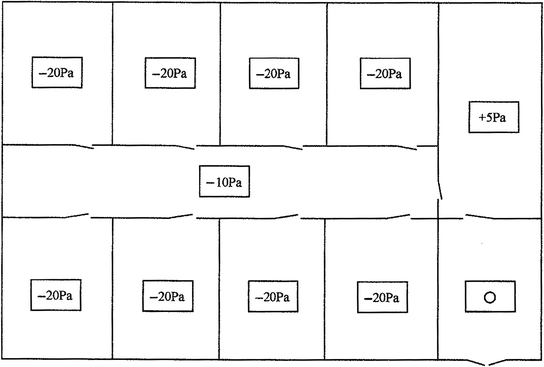
Expression of absolute pressure difference
-
2.
Compared with the pressure in the adjacent room, the direction of the pressure difference is expressed with the arrow at the gate connecting two rooms. The value of the pressure difference is marked beside the arrow or at the end of the arrow. Take the above figure as an example, Fig. 7.13 can be obtained. In Fig. 7.13, the value “−10 Pa” means the pressure difference between the room where the arrow starts and the room where the arrow points to is −10 Pa. The value “+5 Pa” means the pressure difference between the room where the tail of the arrow starts and the room where the arrow points to is +5 Pa. Therefore, both the value of the pressure difference and the location cannot be confused.
It is shown in Figs. 7.13 and 7.14 that these two kinds of expression methods are different.
Fig. 7.14 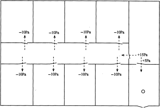
Expression of relative pressure difference
-
3.
In terms of the pressure difference itself, it is aimed to prevent the leakage from adjacent room or the outward leakage towards adjacent room. Because the room studied is connected with the adjacent room, the pressure difference between them is meaningful.
However, it has no practical implication to discuss the leakage towards the ambient air through the envelope or the inward leakage from the ambient air towards indoors. The biosafety laboratory with high class level is an exceptional.
In the layout shown in Fig. 7.15, it is required that:
Fig. 7.15 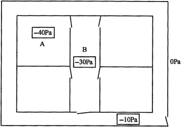
Absolute pressure difference in the plane design
The absolute value of negative pressure in room A ∆P AO ≮ 40 Pa.
The absolute value of negative pressure in corridor B ∆P BO ≮ 30 Pa.
If all the measured data are −40 Pa, the pressure in corridor B does not violate the original requirement. But in fact there is no relative pressure difference between A and B. The design or adjusting results are not reasonable.
Figure 7.16 shows another example. The differential pressure gauge only set on the partition wall between the isolation ward and the polluted corridor, which shows the relative pressure difference between them. Inspection shows that there is no differential pressure gauge between the isolation ward and the buffer room, but the actual pressure difference is 0. In this case, even though the pressure difference between the isolation ward and the polluted corridor meets the requirement, there is no pressure difference between the isolation ward and the buffer room. The buffer room and the isolation ward is combined to be one unit. The function of buffer loses, so the buffer room only exists as a name.
Fig. 7.16 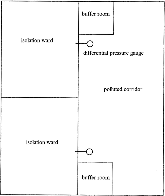
In complete step-by-step expression of relative pressure difference
-
4.
It has been mentioned before that it is difficult to control with the absolute pressure during the actual adjusting process. If one side of the differential pressure sensor connects indoors while the other connects outdoors as shown in Fig. 7.17, the sampled pressure difference is unstable because of the wind direction and wind magnitude of the atmosphere. It may be positive or negative, large or small.
Fig. 7.17 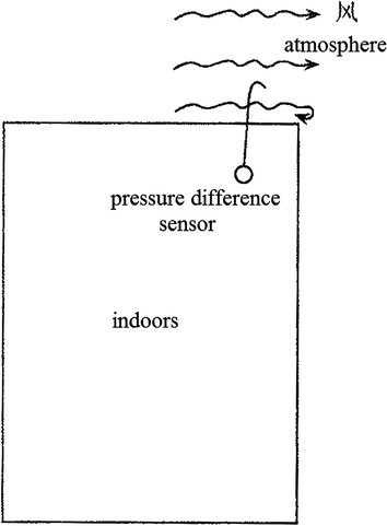
Schematic of piezometric tube connecting the atmosphere
In fact, during the process of system design, the flow rate by negative pressure or positive pressure is calculated based on the relative pressure difference. Figure 7.13 should be expressed as Fig. 7.18. The difference of the exhaust air volume from A and that from B can be calculated. The difference of the exhaust air volume from B and that from the exterior corridor can also be calculated. This has been introduced in Sect. 2.1.2.
Fig. 7.18 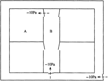
Schematic for design of relative pressure difference in plane
Based on the relative pressure, the corresponding absolute pressure difference relative to atmospheric pressure can be converted. The conversion equation is as follows:
$$\Delta P_{{0,{\text{n}}}} = ( \pm\Delta P_{\text{n}} ) + ( \pm\Delta P_{{{\text{n}} - 1}} ) + ( \pm\Delta P_{{{\text{n}} - 2}} ) + \cdots + ( \pm\Delta P_{ 1} )$$(7.2)where ∆P 0,n is the absolute pressure difference at room n. The value of n is the sequence number of the room n along the passage from outdoors towards indoors. ∆P n is the magnitude of the relative pressure difference between room n and room (n − 1). ∆P n−1 is the magnitude of the relative pressure difference between room (n − 1) and room (n − 2), and so on.
Next we will take the plane layout of a negative pressure room in an animal health company as an example, which is shown in Fig. 7.19.
Fig. 7.19 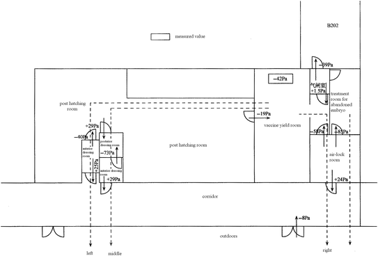
Plane layout of a negative pressure room in an animal health company
Except for the treatment room for abandoned embryo which forms one passage itself, there are three routes for connecting the ambient with the inoculation chamber which needs the highest requirement. These routes are expressed with dashed lines.
-
(a)
The left route can be simplified as Fig. 7.20. We obtain
Fig. 7.20 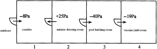
Simplified left route
$$\begin{aligned}\Delta P_{0, 4} & = ( -\Delta P_{ 4} ) + ( -\Delta P_{ 3} ) + ( +\Delta P_{ 2} ) + ( -\Delta P_{ 1} ) \\ & = \left( { - 1 9} \right) + \left( { - 40} \right) + \left( { + 2 5} \right) + \left( { - 8} \right) = - 4 2\,{\text{Pa}} \\\Delta P_{0, 3} & = ( -\Delta P_{ 3} ) + ( +\Delta P_{ 2} ) + ( -\Delta P_{ 1} ) = \left( { - 40} \right) + \left( { + 2 5} \right) + \left( { - 8} \right) = - 2 3\,{\text{Pa}} \\ \end{aligned}$$ -
(b)
The middle route can be simplified as Fig. 7.21. We obtain
Fig. 7.21 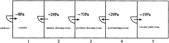
Simplified middle route
$$\begin{aligned}\Delta P_{0, 5} & = ( -\Delta P_{ 5} ) + ( +\Delta P_{ 4} ) + ( -\Delta P_{ 3} ) + ( +\Delta P_{ 2} ) + ( -\Delta P_{ 1} ) \\ & = \left( { - 1 9} \right) + \left( { + 2 9} \right) + \left( { - 7 3} \right) + \left( { + 2 9} \right) + \left( { - 8} \right) = - 4 2\,{\text{Pa}} \\\Delta P_{0, 4} & = ( +\Delta P_{ 4} ) + ( -\Delta P_{ 3} ) + ( +\Delta P_{ 2} ) + ( -\Delta P_{ 1} ) \\ & = \left( { + 2 9} \right) + \left( { - 7 3} \right) + \left( { + 2 9} \right) + \left( { - 8} \right) = - 2 3\,{\text{Pa}} \\ \end{aligned}$$ -
(c)
The right route can be simplified as Fig. 7.22. We obtain
$$\Delta P_{0, 3} = ( -\Delta P_{ 3} ) + ( +\Delta P_{ 2} ) + ( -\Delta P_{ 1} ) = \left( { - 5 8} \right) + \left( { + 2 4} \right) + \left( { - 8} \right) = - 4 2\,{\text{Pa}}$$Fig. 7.22 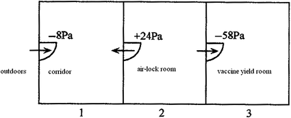
Simplified right route
It is shown that when anyone route is chosen among the left, middle and right routes, the absolute pressure differences for the inoculation chamber obtained with relative pressure difference are the same. This is the same as the in situ measured absolute pressure difference.
Similarly the absolute pressure difference in the treatment room for abandoned embryo can be obtained:
$$\Delta P = \left( { - 8 5} \right) + \left( { + 2 4} \right) + \left( { - 8} \right) = - 6 2\,{\text{Pa}}$$It is known from Fig. 7.21 that even though the relative pressure in the inoculation chamber compared with that in the post hatching room is “+10 Pa”, the absolute pressure difference is still:
$$\Delta P = \left( { + 10} \right) + \left( { - 40} \right) + \left( { + 2 5} \right) + \left( { - 8} \right) = - 1 3\,{\text{Pa}}$$This means because the relative pressure difference in the post hatching room close to the inoculation chamber is −40 Pa, although the relative difference between the inoculation chamber and the post hatching room reaches +10 Pa, the condition of negative pressure compared with atmospheric pressure can still not be changed.
To determine whether the relative pressure in a room compared with atmospheric pressure is negative or not, calculation with various adjacent rooms connecting outdoors should be performed.
-
5.
Differential pressure gauges should be set at the view height on each exterior wall of the region where the pressure difference is required.
-
(a)


7.7 Design Case
7.7.1 Self-circulation System with Fan Coil Unit
Since the indoor cooling load is dealt with the fan coil unit, the capacity of the outdoor air handling unit reduces.
Because the bacterial removal efficiency of the HEPA filter on the return air grille reaches more than 99.9999%, one bacterium can penetrate through only when the indoor bacterial concentration reaches millions per cubic meter. In common situation, indoor bacterial concentration cannot reach such high value. Therefore, the return air is quite clean. The problem for deposition and accumulation of dust and bacteria on fan coil unit is not a concern.
Therefore, air filters with performance lower than sub-HEPA filter can be installed for the supplied air, such as the low-resistance and high and medium efficiency air filter, or even fine filter. The unit with static pressure between 30 and 50 Pa should be selected.
The problem of condensation should be paid attention to.
The system is shown in Fig. 7.23.

Self-circulation system with fan coil unit
7.7.2 Air Supply Outlet and Fan System
Condensation water is very likely to appear in the coil when the fan coil unit is adopted, which is not expected to occur. So in the current scheme, the coil is abandoned, which is replaced by the ordinary supplied air fan. The return air needs to pass through the outdoor air handling unit, which increases the burden of the outdoor air handling unit.
The system is shown in Fig. 7.24.

Scheme one with air supply outlet and fan system
7.7.3 Air Supply Outlet and Indoor Self-circulation Fan System
Because there are 1–2 patients in the ward, the cooling and humidity loads are very small. If there is no need of cooling and humidity handling for the return air, return air will not pass through the outdoor air handling unit. The outdoor air handling unit is only responsible for the cooling and humidity loads from the outdoor air. In this case, there is no problem for formation of condensation water. Liu Hua proposed the specific scheme which is shown in Fig. 7.25.

Scheme two with air supply outlet and fan system
In this scheme, by reducing the dew point of the machine and increasing the outdoor air volume, the problem of the outdoor air handling unit to treat the entire humidity load is solved. When the outdoor air volume is increased, the air change rate of the outdoor air for the double-bed ward is only 3.1 h−1, which only increases by 1 h−1.
Based on the meteorological condition in Shanghai, the surface air cooler with six rows of coils in the outdoor air handling unit can meets the requirement of the design (t < 26 °C and φ < 60%). When other types of coils are used, eight rows of coils are enough.
The system is shown in Fig. 7.25.
7.7.4 Layout Plan for an Isolation Ward as an Example
Figure 7.26 shows the schematic of the system which was designed by Liu Hua and Liang Lei. One example of the double-bed isolation ward for this scheme is shown in Fig. 7.27.

Plane layout of the isolation ward

Example for the plane layout of the double-bed isolation ward. 1 Primary air supply grille; 2 Secondary air supply slot; 3 Air supply outlet with sub-HEPA filter; 4 Air return (or exhuast) opening which includes leakage-free high efficiency air return device
-
1.
Outline
The isolation ward is located on the 12th floor with area 1600 m2. There are twelve negative pressure isolation wards and four ordinary wards. Every two wards share the same anterior buffer room. Each ward has its posterior buffer room. Moreover, buffer room is placed at all the entrance and exit. This realizes the feature of “Three-Area-Two-Buffer”. Three-Area means the clean, the potentially polluted and the polluted areas. Two-Buffer means the buffer room between the ward and the corridor, and the buffer room between the corridor and outdoors. The isolation capability is greatly increased. Independent air conditioning system is used for each area. In the clean area, the scheme with the fan coil unit and the dedicated outdoor air handling unit is used. In the potentially polluted area, the dedicated all air system is used. In the polluted area, independent all air system is adopted for every isolation ward, which operates with two gears of velocity. In other regions, an independent all air system is adopted.
The air change rates in the ward and the buffer room are 12 and 60 h−1, respectively.
The gradient of the pressure is also marked in Fig. 7.26.
-
2.
Simplified analysis
-
3.
Corridors are set in front and back of the ward, which realizes the separation of clean and dirty matter.
-
4.
Buffer rooms are set in front and back of the ward. Buffer rooms are also set between the corridor and outdoors. These greatly increase the isolation performance and safety. By adapted to local conditions, there is no obvious occupation of floor area. Positive pressure should be kept in the buffer room 4.
-
5.
The ward is set at one side, while the auxiliary rooms are set at the other side. The arrangement is uniform, which is good for usage and pollution control.
-
6.
The opening direction for the door of the anterior should be opposite, since the pressure in the anterior is higher than that in the ward.
-
7.
Air supply outlet should be placed on the ceiling above the middle of the two beds in the double-bed ward, which is beneficial to control the dispersion of pollutant.
-
8.
Since the leakage-free negative pressure high efficiency air exhaust device is installed at the return air grille, the return air can be switched on. Because the bacterial removal efficiency of the HEPA filter on the return air grille reaches more than 99.9999% and there is no leakage on the frame of air filter, one bacterium in the return air can penetrate through only when the indoor bacterial concentration reaches millions per cubic meter or even tens of millions per cubic meter. But the probability of this incidence is extremely small.
-
9.
For the installation style of the fan coil unit on the ceiling, the problem for the accumulation and removal of condensation water once occurred should be solved.
7.7.5 Design Parameters
Table 7.6 shows the design parameters of the negative pressure isolation ward for reference.
References
AIA, Guidelines for Design and Construction of Hospital and Health Care Facilities (1998)
J. Shen, Y. Liu, Isolation room and HVAC design for SARS rooms. J. HV&AC 33(4), 10–14 (2003)
Z. Xu, Q. Wang, Y. Zhang, H. Liu, W. Niu, R. Wang, The safe distance of a biosafety lab considered from the angle of exhaust air diffusion. Build. Sci. 20(4), 46–50 (2004)
Z. Xu, Introduction of Cleanroom and Design of its Controlled Environment (Chemical Industry Press, Beijing, 2008), pp. 248–250
Author information
Authors and Affiliations
Corresponding author
Rights and permissions
Copyright information
© 2017 Springer Nature Singapore Pte Ltd.
About this chapter
Cite this chapter
Xu, Z., Zhou, B. (2017). Design Points for Negative Pressure Isolation Ward. In: Dynamic Isolation Technologies in Negative Pressure Isolation Wards. Springer, Singapore. https://doi.org/10.1007/978-981-10-2923-3_7
Download citation
DOI: https://doi.org/10.1007/978-981-10-2923-3_7
Published:
Publisher Name: Springer, Singapore
Print ISBN: 978-981-10-2922-6
Online ISBN: 978-981-10-2923-3
eBook Packages: EngineeringEngineering (R0)