
Abstract
There are many devices such as three-phase ac generator, transformer etc., which are usually used in a power station to generate and supply electrical power to a power system network. In the power station, the three-phase ac generator generates a three-phase alternating voltage in the range between 11 and 20 kV. The magnitude of the generated voltage is increased to 120 kV or more by means of a power transformer. This higher magnitude of voltage is then transmitted to the grid substation by a three-phase transmission lines. A lower line voltage of 415 V is achieved by stepping down either from the 11 or 33 kV lines by a distribution transformer. In these cases, a three-phase transformer is used in either to step-up or step-down the voltage. Since a transformer plays a vital role in feeding an electrical network with the required voltage, it becomes an important requirement of a power system engineer to understand the fundamental details about a transformer along with its analytical behavior in the circuit domain. This chapter is dedicated towards this goal. On the onset of this discussion it is worth mentioning that a transformer, irrespective of its type, contains the following characteristics (i) it has no moving parts, (ii) no electrical connection between the primary and secondary windings, (iii) windings are magnetically coupled, (iv) rugged and durable in construction, (v) efficiency is very high i.e., more than 95 %, and (vi) frequency is unchanged.
This is a preview of subscription content, log in via an institution.
Buying options
Tax calculation will be finalised at checkout
Purchases are for personal use only
Learn about institutional subscriptionsReferences
T. Wildi, Electrical Machines, Drives and Power Systems, 6th edn. (Pearson Education International, Upper Saddle River, 2006)
M.A. Salam, Fundamentals of Electrical Machines, 2nd edn. (Alpha Science, International Ltd., Oxford, 2012)
S.J. Chapman, Electric Machinery and Power System Fundamentals (McGraw-Hill Higher Education, New York, 2002)
A.E. Fitzgerald, C. Kingsley Jr., S.D. Umans, Electric Machinery, 6th edn (McGraw-Hill Higher Education, New York, 2003)
Author information
Authors and Affiliations
Corresponding author
Exercise Problems
Exercise Problems
-
2.1
A single-phase transformer is having the primary voltage of 240 V. The number of turns at the primary and secondary coils are 250 and 50, respectively. Determine the secondary voltage.
-
2.2
A single-phase transformer is having the secondary voltage of 100 V. The number of turns at the primary and secondary windings are 500 and 50, respectively. Calculate the primary voltage.
-
2.3
The 100 A current flows in the primary coil of a single-phase transformer. Calculate the secondary current with the turns ratio of 0.05.
-
2.4
The number of turns at the primary and secondary windings of a single-phase transformer are 500 and 100, respectively. Find the primary current if the secondary current is 10 A.
-
2.5
The ratio of the primary current to the secondary current of a single-phase transformer is 1:10. Find the voltage ratio. Also, find the secondary voltage if the primary voltage is 100 V.
-
2.6
The turns ratio of a single-phase transformer is 1:4. The secondary coil has 5000 turns and 60 V. Find the voltage ratio, primary voltage and number of turns.
-
2.7
The voltage ratio of a single-phase transformer is 5:1. The voltage and number of turns at the primary coil are found to be 1100 V and 500, respectively. Calculate the voltage and secondary number of turns at the secondary coil.
-
2.8
A single-phase transformer is connected to the 120 V source draws 4 A current. Calculate the current in the secondary coil when the transformer steps up the voltage to 500 V.
-
2.9
The number of turns at the primary and secondary coils of a single-phase transformer are found to be 480 and 60, respectively. The transformer draws a current of 0.6 A when connected to 120 V supply. Determine the current and the voltage at the secondary coil.
-
2.10
The turns ratio of a 5 kVA single-phase transformer is found to be 2. The transformer is connected to a 230 V, 50 Hz supply. If the secondary current of a transformer is 6 A, then find the primary current and secondary voltage.
-
2.11
The secondary number of turns of a 30 kVA, 4400/440 V single-phase transformer is found to be 100. Find the number of primary turns, full load primary and secondary currents.
-
2.12
A 5 kVA, 1100/230 V, 50 Hz single-phase transformer is installed near the domestic area of a country. Find the turns ratio, primary and secondary full load currents.
-
2.13
The number of turns of the primary winding of a single-phase 50 Hz transformer is found to be 50. Find the value of the core flux, if the induced voltage at this winding is 220 V.
-
2.14
The number of primary turns of a 60 Hz single-phase transformer is found to be 500. Calculate the induced voltage in this winding, if the value of the core flux is 0.05 Wb.
-
2.15
The maximum flux of a 3300/330 V, 50 Hz step-down single-phase transformer is found to be 0.45 Wb. Calculate the number of primary and secondary turns.
-
2.16
The cross sectional area of a 5 kVA, 2200/220 V, 50 Hz single-phase step-down transformer is found to be 25 cm2 and a maximum flux density is 4 Wb/m2. Calculate the primary and secondary turns.
-
2.17
The number of turns at the primary and secondary of an ideal single-phase transformer are found to be 500 and 250, respectively. The primary of the transformer is connected to a 220 V, 50 Hz source. The secondary coil supplies a current of 5 A to the load. Determine the (i) turns ratio, (ii) current in the primary and (iii) maximum flux in the core.
-
2.18
The primary number of turns of a 4 kVA, 1100/230 V, 50 Hz single-phase transformer is 500. The cross sectional area of the transformer core is 85 cm2. Find the (i) turns ratio, (ii) number of turns in the secondary and (iii) maximum flux density in the core.
-
2.19
The primary and secondary turns of a single-phase transformer are 50 and 500, respectively. The primary winding is connected to a 220 V, 50 Hz supply. Find the (i) flux density in the core if the cross sectional area is 250 cm2 and (ii) induced voltage at the secondary winding.
-
2.20
The primary coil number of turns of a single-phase 2200/220 V, 50 Hz transformer is found to be 1000. Find the area of the core if the maximum flux density of the core is 1.5 Wb/m2.
-
2.21
The maximum flux of a single-phase 1100/220 V, 50 Hz transformer is found to be 5 mWb. The number of turns and the voltage at the primary winding are found to be 900 and 1100 V, respectively. Determine the frequency of the supply system.
-
2.22
The maximum flux density of a 6 kVA, 2200/220 V, 50 Hz single-phase transformer is found to be 0.6 Wb/m2. The induced voltage per turn of the transformer is 10 V. Calculate the (i) primary number of turns, (ii) secondary number of turns, and (iii) cross sectional area of the core.
-
2.23
A single-phase transformer is having the primary voltage per turn is 20 V. Find the magnetic flux density if the cross sectional area of the core is 0.05 m2.
-
2.24
The no load primary current of an 1100/230 V single-phase transformer is found to be 0.5 A and absorbs a power of 350 W from the circuit. Find the iron loss and magnetizing components of the no-load current.
-
2.25
A 3300 V/230 V single-phase transformer draws a no-load current of 0.5 A at a power factor of 0.4 in an open circuit test. Determine the working and magnetizing components of the no-load current.
-
2.26
A single-phase transformer draws a no-load current of 1.4 A from the 120 V source and absorbs a power of 80 W. The primary winding resistance and leakage reactance are found to be 0.25 and \(1.2\,\Omega\), respectively. Determine the no-load circuit resistance and reactance.
-
2.27
Under no-load condition, a single-phase transformer is connected to a 240 V, 50 Hz supply and draws a current of 0.3 A at a 0.5 power factor. The number of turns on the primary winding is found to be 600. Calculate the (i) maximum value of the flux in the core, (ii) magnetizing and working components of the no load current, and (iii) iron loss.
-
2.28
The no-load current of a 440/110 V single-phase transformer is measured 0.8 A and absorbs a power of 255 W. Calculate the (i) working and magnetizing components of the no-load current, (ii) copper loss in the primary winding if the primary winding resistance is \(1.1\,\Omega\), and (iii) core loss.
-
2.31
The primary winding resistance and reactance of a 300 kVA, 2200/220 V single-phase transformer are 2 and 9 Ω, respectively. The secondary winding resistance and reactance are found to be 0.02 and 0.1 Ω, respectively. Find the equivalent impedance referred to the primary and the secondary.
-
2.32
The primary winding resistance and reactance of a 200 kVA, 3300/220 V single-phase transformer are found to be 5 and 12 Ω, respectively. The same parameters in the secondary winding are found to 0.02 and 0.05 Ω, respectively. Find the equivalent impedance referred to the primary and the secondary. Also, determine the full load copper loss.
-
2.33
A 1100/400 V single-phase transformer having the resistance of 5 Ω and the reactance of 9 Ω in the primary winding. The secondary winding resistance and reactance are found to be 0.6 and 1.1 Ω respectively. Find the voltage regulation when the secondary delivers a current of 5 A at a 0.9 lagging power factor.
-
2.34
A 2200/220 V single-phase transformer having the resistance of 6 Ω and the reactance of 16 Ω in the primary coil. The resistance and the reactance in secondary winding are found to be 0.07 and 0.15 Ω, respectively. Find the voltage regulation when the secondary supplies a current of 6 A at a 0.86 power factor leading.
-
2.35
The iron loss and full load copper loss of a 40 kVA transformer are found to be 450 and 750 W, respectively. Calculate the (i) full load efficiency, (ii) output kVA corresponding to maximum efficiency, and (iii) maximum efficiency. Consider the power factor of the load is 0.95 lagging.
-
2.36
The iron loss of a 40 kVA transformer is 50 % of the full load copper loss. The full load copper loss is found to be 850 W. Calculate the (i) full load efficiency, (ii) output kVA corresponding to maximum efficiency, and (iii) maximum efficiency. Assume the power factor of the load is 0.9 lagging.
-
2.37
The iron loss and full load copper loss of a 25 kVA transformer are found to be 300 and 550 W, respectively. Find the (i) full load efficiency, (ii) output kVA corresponding to maximum efficiency, and (iii) maximum efficiency. Assume the power factor of the load is 0.6 lagging.
-
2.38
The primary and secondary windings parameters of a 100 kVA, 2200/220 V transformer are \(R_{1} = 0.6\,\Omega\), \(X_{1} = 0.9\,\Omega\), \(R_{2} = 0.007\,\Omega\), \(X_{2} = 0.008\,\Omega\). The transformer is operating at a maximum efficiency of 75 % of its rated load with 0.9 lagging power factor. Calculate the (i) efficiency of transformer at full load, and (ii) maximum efficiency, if the iron loss is 350 W.
-
2.39
A 200 kVA, 2400/240 V transformer has the primary and windings parameters \(R_{1} = 20\,\Omega\), \(X_{1} = 27\,\Omega\), \(R_{2} = 0.18\,\Omega\), \(X_{2} = 0.26\,\Omega\). The transformer is operating at a maximum efficiency of 80 % of its rated load with 0.8 pf lagging. Calculate the (i) efficiency of the transformer at full load, and (ii) maximum efficiency if the iron loss is 400 W.
-
2.40
The low voltage side of a 30 kVA, 2400/220 V, 50 Hz single-phase transformer is short circuited. The test data recorded from the high voltage side are 200 W, 6 A and 45 V. Find the (i) equivalent resistance, reactance and impedance referred to the primary, (ii) equivalent resistance, reactance and impedance referred to the secondary, and (iii) voltage regulation at 0.6 power factor lagging.
-
2.41
The low voltage winding of a 25 kVA, 1100/220 V, 50 Hz single-phase transformer is short circuited. The test data recorded from the high voltage side are 156 W, 4 A and 50 V. Calculate the (i) equivalent resistance, reactance and impedance referred to the primary, (ii) equivalent resistance, reactance and impedance referred to the secondary, and (iii) voltage regulation at 0.85 power factor leading.
-
2.42
The test data of a 10 kVA, 440/220 V, 50 Hz single-phase transformer are as follows:
-
Open circuit test: 220 V, 1.4 A, 155 W;
-
Short circuit test: 20.5 V, 15 A, 145 W;
Calculate the approximate equivalent circuit parameters.
-
-
2.43
The open circuit test data of a single-phase transformer are recorded as the 220 V, 1.2 A and 145 W. Find the no-load circuit parameters.
-
2.44
A single-phase 100 kVA, 1100/220 V transformer is connected as an autotransformer, which is shown in Fig. P2.1. The voltage of the upper portion and lower portion of the coil are found to be 220 and 1100 V, respectively. Calculate the kVA rating of the autotransformer.
Fig. P2.1 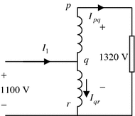
An autotransformer with a specific voltage
-
2.45
A 200 kVA three-phase, 50 Hz core-type transformer is connected as delta-wye and has a line voltage ratio of 1100/440 V. The core area and the maximum flux density of the transformer are found to be \(0.04\,{\text{m}}^{2}\) and \(2.3\,{\text{Wb/m}}^{2}\), respectively. Calculate the number of turns per phase of the primary and secondary coils.
-
2.46
The number of turns in the primary and secondary coils are found to be 600 and 150, respectively. The transformer is connected to 11 kV, 50 Hz supply. Find the secondary line voltage when the windings are connected as (a) delta-wye, and (b) wye-delta.

Rights and permissions
Copyright information
© 2016 Springer Science+Business Media Singapore
About this chapter
Cite this chapter
Salam, M.A., Rahman, Q.M. (2016). Transformer: Principles and Practices. In: Power Systems Grounding. Power Systems. Springer, Singapore. https://doi.org/10.1007/978-981-10-0446-9_2
Download citation
DOI: https://doi.org/10.1007/978-981-10-0446-9_2
Published:
Publisher Name: Springer, Singapore
Print ISBN: 978-981-10-0444-5
Online ISBN: 978-981-10-0446-9
eBook Packages: EnergyEnergy (R0)