
Abstract
Prerequisites:
-
Knowledge of circuit elements, their υ-i characteristics, and Ohm’s law (Chap. 2)
Access this chapter
Tax calculation will be finalised at checkout
Purchases are for personal use only
Notes
- 1.
The KCL and KVL concepts are so powerful that they even find applications in equivalent form in magnet systems such as transformers and motors. For example, the magnetic flux in a yoke with air gaps can be model according to KCL and KVL.
- 2.
The physical counterpart of KVL is Faraday’s law of induction in the static case. When there is a variable magnetic field penetrating a wire loop, KVL is no longer valid.
- 3.
If realistic battery cells are capable of delivering different currents when short circuited, then the lowest cell current will flow under short circuit condition.
Author information
Authors and Affiliations
Appendices
Summary

(continued)

(continued)

Problems
1.1 3.1 Circuit Laws: Networking Theorems
3.1.1 Electric Network and Its Topology
Problem 3.1
In the network graph shown in the figure below:
-
A.
Find the number of branches, single nodes (nodes with distinct voltages), and meshes.
-
B.
Prove the equality b = n + m − 1 for the number of branches b, meshes m, and single nodes n.

Problem 3.2
Repeat problem 3.1 for the circuits shown in the following figures.

Problem 3.3
Repeat problem 3.1 for the circuit shown in the figure that follows. Each straight segment is now a branch.

3.1.2 Kirchhoff’s Current Law (KCL)
Problem 3.4
Find current IB for the node shown in the figure that follows.

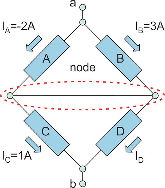
Problem 3.5
-
A.
Find current ID for the node shown in the figure below.
-
B.
Redraw this node (and the circuit between terminals a and b) in an equivalent form eliminating the horizontal wire.

Problem 3.6
Determine current iC for the circuit shown in the figure that follows.

Problem 3.7
Find a relation between currents iC, iE for the circuit shown in the figure that follows. Does the problem have a unique solution?

Problem 3.8
Find currents iA, iB, iD, iH for the circuit shown below.

Problem 3.9
Determine currents iC, iF, iH for the circuit shown in the figure that follows.

Problem 3.10
Determine currents iC, iF, iH in the figure that follows.

Problem 3.11
Find all unknown currents for the circuit shown in the figure below.

3.1.3 Kirchhoff’s Voltage Law (KVL)
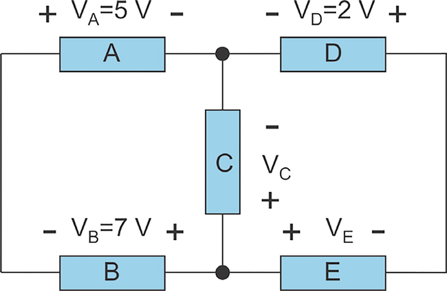
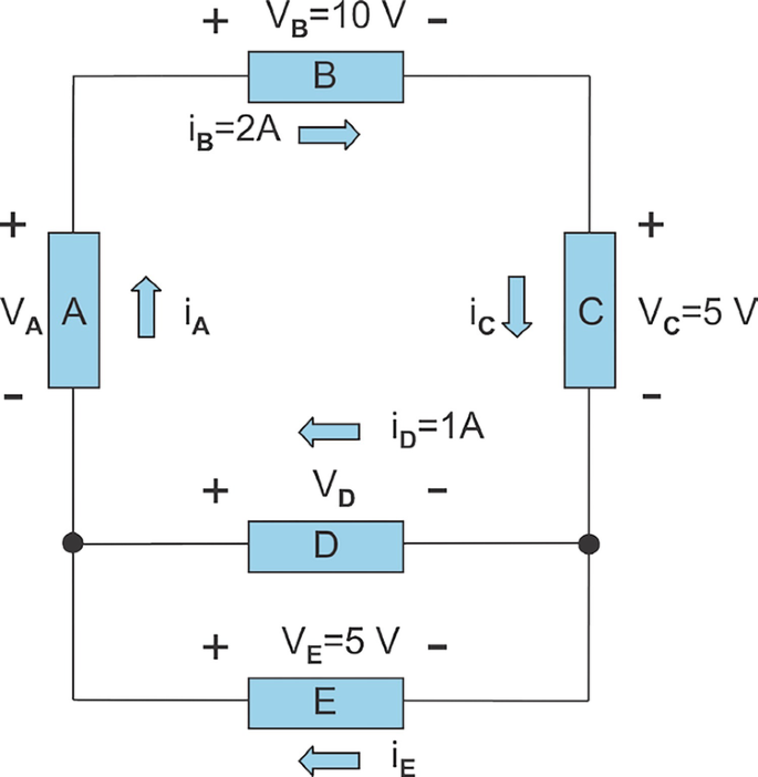
Problem 3.12
-
A.
Find voltage VC for the circuit shown in the figure that follows;
-
B.
How would the solution change if VD were equal to 0 V?
-
C.
Could the value VE = 0 V be used in this problem?

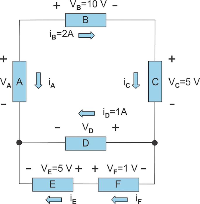
Problem 3.13
Determine voltage VF in the circuit shown in the figure below.

Problem 3.14
Find the unknown voltages VA, VB, VG, VH for the circuit shown in the figure below.

Problem 3.15
Determine voltage VE for the circuit shown below.

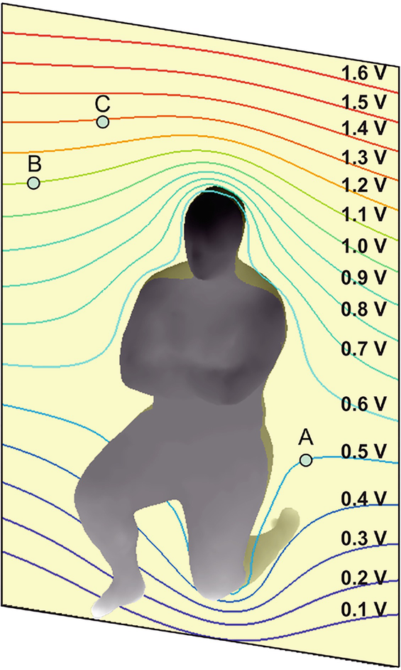
Problem 3.16
Equipotential lines for a human body subject to a vertical electric field with the strength of 1 V/m are shown in the figure that follows.
-
A.
Determine voltages VAB, VBC, VCA.
-
B.
Establish the KVL loop and formulate KVL for these three voltages.

3.1.4 Power-Related Theorems
Problem 3.17
For the circuit shown in the figure that follows:
-
(i)
Determine which circuit elements are resistances and which are sources.
-
(ii)
Find the power (delivered to the circuit or taken from the circuit) for every circuit element.
-
(iii)
Assuming that the powers of the sources are negative, find the sum of all powers in the circuit.
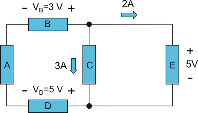

Problem 3.18
For the circuit shown in the figure:
-
1.
Use KVL and KCL to solve for unknown currents and voltages.
-
2.
Find the power (delivered to the circuit or taken from the circuit) for every circuit element.
-
3.
Assuming that the powers of the sources are negative, find the algebraic sum of all powers in the circuit.

Problem 3.19
For the circuit shown in the figure:
-
1.
Use KVL to solve for the unknown voltages.
-
2.
Use KCL to solve for the unknown currents.
-
3.
For each of six circuit elements, determine if the element is a resistance or a source.
-
4.
Assuming that the source powers are negative, find the algebraic sum of all powers in the circuit.

1.2 3.2 Series and Parallel Network/Circuit Blocks
3.2.1 Sources in Series and in Parallel
Problem 3.20
The electronic circuits onboard an 18-foot long Parker motor boat consume 96 W when operated from a 24-V source. The source is a combination of two fully charged deep-cycle batteries, each of which is rated for 12 V and 100 ampere hours.
-
1.
Should the batteries be connected in series or in parallel?
-
2.
For how many hours can the electronics be operated from the battery bank without recharging?
-
3.
How much energy in kilowatt hours is initially stored in each battery?
Problem 3.21
A certain sensing device consumes 0.375 W of power over a 20 h period and operates from a 6 V source. The source is a combination of four fully charged AAA batteries, 1.5 V each. The batteries discharge by the end of the 20 h period.
-
1.
Should the batteries be connected in series or in parallel?
-
2.
What is a typical capacity of the AAA battery?
-
3.
How much energy in watt hours is initially stored in each battery?
Problem 3.22
A load has the resistance of 1.5 Ω and requires the applied voltage of 3 V. A number of battery cells are given, each of which is rated for 1.5 V. Each cell may deliver no more than 1 A of current.
-
1.
Construct and draw a battery bank that could be used to drive the load.
-
2.
Is the solution to the problem unique?
Problem 3.23
Repeat the previous problem when the required load voltage is changed to 6 V.
3.2.2 Resistances in Series and in Parallel
3.2.3 Reduction of Resistive Networks
Problem 3.24
Determine the equivalent resistance between terminals a and b.

Problem 3.25
The equivalent electric circuit for a car rear window defroster is shown in the figure below. All resistances are equal: R1 = … = R15 = 10 Ω. Determine the heat power (power delivered to the defroster).

Problem 3.26
Find the equivalent resistance between terminals a and b.

Problem 3.27
Find the equivalent resistance between terminals a and b.

Problem 3.28
Find the equivalent resistance between terminals a and b.

Problem 3.29
Determine the equivalent resistance between terminals a and b.

Problem 3.30
Find the equivalent resistance between terminals a and b.

Problem 3.31
Determine the equivalent resistance (resistance between ports a and b) of the network shown in the figure that follows.

Problem 3.32
Determine the equivalent resistance between terminals a and b.

Problem 3.33
Find the equivalent resistance between terminals a and b.

Problem 3.34
Determine the equivalent resistance of the network (resistance between terminals a and b) shown in the figure below.

Problem 3.35
Determine the equivalent resistance between terminals a and b (show units).

Problem 3.36
A network shown in the figure below is known as a ladder. The ladder network includes one particular section with a series (R1 = 1 Ω) and a shunt (R2 = 1 Ω) resistance, known as the L-section. This section is then repeated an infinite number of times to the right. Determine the equivalent resistance between terminals a and b of the ladder network.

Hint: For the semi-infinite ladder network in the previous figure, the equivalent resistance, Req, will not change after adding a new section up front as shown in the figure that follows.

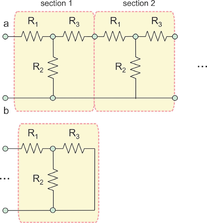
Problem 3.37
-
A.
Repeat the previous problem for the semi-infinite ladder network circuit shown in the same figure when R1 = R3 = 10 Ω and R2 = 25 Ω.
-
B.
How different is your result from the equivalent resistance of the finite ladder network with only four sections?
Problem 3.38
Another important ladder network type (with the T-section) is shown in the figure.
-
A.
Determine the equivalent resistance between terminals a and b of the ladder network when R1 = 2R3 = 10 Ω and R2 = 10 Ω.
-
B.
How different is your result from the equivalent resistance of the finite ladder network with only four sections?

3.2.4 Voltage Divider Circuit
Problem 3.39
Redraw the circuit shown in the figure that follows and plot the distribution of the circuit voltage versus ground reference point to scale between two circuit points a and b as a function of distance x from point a.

Problem 3.40
Repeat the task of the previous problem for the disconnected circuit shown in the figure below.

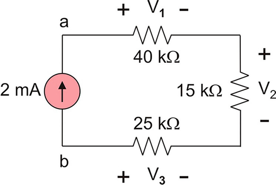
Problem 3.41
For the circuit shown in the figure that follows, use the voltage division principle to calculate V1, V2, V3.

Problem 3.42
For the circuit shown in the following figure:
-
A.
Calculate V1, V2, V3.
-
B.
Find the voltage across the current source.

Problem 3.43
For the circuits shown in the figure that follows, determine voltages V1, V2, absolute voltage Va at node a versus ground (show units), and circuit current I.

3.2.5 Application Example: Voltage Divider as a Sensor Circuit
3.2.6 Application Example: Voltage Divider as an Actuator Circuit
Problem 3.44
An NTC thermistor-based temperature sensor should operate between 25° C and 65° C from a 6 V DC power supply. The thermistor’s resistance changes from R′ = 50 kΩ to R′′ = 20 kΩ in this temperature range.
-
A.
Present a circuit diagram for the simple temperature sensor.
-
B.
Determine the value of the unknown resistance for the maximum circuit sensitivity.
-
C.
Determine the maximum circuit sensitivity.
-
D.
What is the circuit sensitivity when the unknown resistance is set to 1 kΩ?
Problem 3.45
In the previous problem, using software of your choice (MATLAB is recommended), plot the circuit sensitivity to scale as a function of the value of the unknown resistance in the range from 1 kΩ to 100 kΩ.
Problem 3.46
A strain gauge with nominal resistance of 120 Ω is used in conjunction with a 2.5 V DC voltage source. Its nominal resistance changes by ±0.2% when the gauge operates in the permissible strain range, which is ±1000με.
-
A.
Present a circuit diagram for the simple strain gauge sensor.
-
B.
Determine the value of the unknown resistance for the maximum circuit sensitivity.
-
C.
Determine the maximum circuit sensitivity.
-
D.
What is the circuit sensitivity when the unknown resistance is set to1 kΩ?
Problem 3.47
In the previous problem, using software of your choice (MATLAB is recommended), plot the circuit sensitivity to scale as a function of the value of the unknown resistance in the range from 10 Ω to 1000 Ω.
Problem 3.48
A voltage divider circuit with R1 = 700 Ω (the fixed resistance) and R2 = 700 Ω ± 0.1% (the strain gauge) is used. The voltage power supply is rated at 4.5 V.
-
A.
Show that voltage across the strain gauge varies in the range 2.25 V ± 1.125 mV.
-
B.
Can you derive an analytical formula that gives the voltage variation across R2 = R1 ± Δ as a linear function of an arbitrary (but very small) resistance variation Δ? [Hint: use your calculus background—the Maclaurin series versus a small parameter.]
3.2.7 Current Limiter
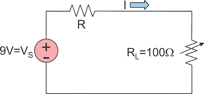
Problem 3.49
A thermistor is connected to an ideal voltage power source of 9 V. Determine the value of the current-limiting resistor R based on the requirement that the power delivered to the thermistor should be always less than 0.1 W. The lowest possible value of R should be chosen. Consider two cases:
-
1.
Thermistor resistance is exactly 100 Ω.
-
2.
Thermistor resistance changes from 200 Ω to 100 Ω.

3.2.8 Current Divider Circuit
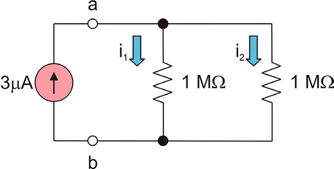
Problem 3.50
For the circuit shown in the figure that follows:
-
A.
Calculate voltage between terminals a and b. Show its polarity on the figure.
-
B.
Use the current division principle to calculate branch currents i1, i2.

Problem 3.51
Find branch currents i1, i2 for the circuit depicted in the figure below.

Problem 3.52
Find branch currents i1, i2 for the circuit shown in the figure that follows.

Problem 3.53
Find the voltage between terminals a and b (voltage across the current power source) for the circuit shown in the figure that follows.

Problem 3.54
The voltage source in the circuit is delivering 0.2 W of electric power. Find R.

3.2.9 Wheatstone Bridge
Problem 3.55
Describe in your own words the function and the scope of the Wheatstone bridge.
Problem 3.56
Find the voltage between terminals a and b for the circuit shown in the figure that follows.

Problem 3.57
Find the voltage between terminals a and b for the circuits shown in the figure that follows.

Problem 3.58
You are given:
-
(i)
A photoresistor that changes its resistance from 20 kΩ for brightness to 500 kΩ for darkness
-
(ii)
A 9 V battery
-
(iii)
A voltmeter (DMM)
-
(iv)
Any other necessary precise resistors
Construct (present the circuit diagram) a Wheatstone bridge sensor circuit that:
-
(i)
Has zero voltage reading for brightness
-
(ii)
Has maximum possible voltage reading for darkness (has maximum sensitivity)
Problem 3.59
You are given:
-
1.
A SGT-1/350-TY11 uniaxial strain gauge with the nominal resistance of 350 Ω (no strain)
-
2.
A 4.5 V voltage source
-
3.
Any number of precise resistors, of any value
When tensile strain is applied, a resistance variation up to +0.1% is observed. Present the circuit diagram for the Wheatstone bridge sensor circuit that:
-
(i)
Has zero voltage reading at no strain
-
(ii)
Has maximum possible voltage response when strain is present (has maximum sensitivity)
-
(iii)
Outputs positive voltages when the resistance of the strain gauge increases
Problem 3.60
Resistance of a strain gauge increases when its length increases (a bended surface under test becomes convex) and decreases when its length decreases (a bended surface under test becomes concave). The corresponding strains are the tensile strain and the compressive strain. You are given two strain gauges (#1 and #2), which are attached to opposite sides of a thin bended surface under test, at the same position. The gauge resistance at normal conditions (no bending) is R = 100 Ω. You are also given any number of fixed resistors, of any value.
-
1.
Suggest and sketch a sensor circuit which will convert changes in the resistance into measurable voltage changes. This circuit should possibly have:
-
(a)
Zero sensor output voltage at normal sensor conditions (no bending)
-
(b)
Maximum voltage sensitivity to changes in resistance (sensitivity to the strain)
-
(a)
-
2.
Label one (or two) strain gauges used, and specify the values of all deployed resistances.
-
3.
Show power supply and DMM connections.
Combined Voltage and Current Dividers
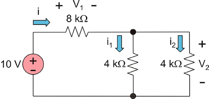
Problem 3.61
For the circuit shown in the figure:
-
A.
Find currents i, i1, i2 (show units).
-
B.
Find power P delivered by the voltage source to the circuit.
-
C.
Find voltages V1, V2.

Problem 3.62
Find voltage V across the 20 kΩ resistance and current i for the circuit shown in the figure that follows.

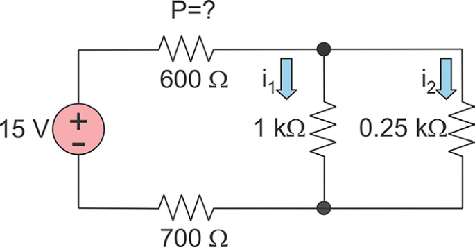
Problem 3.63
For the circuit that follows determine:
-
A.
Current i2 through the 0.25 kΩ resistance
-
B.
Power P absorbed by the 600 Ω resistance

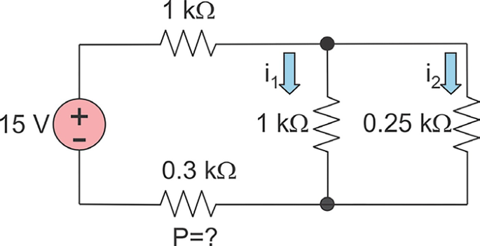
Problem 3.64
For the circuit shown in the figure determine:
-
A.
Current i2 through the 0.25 kΩ resistance,
-
B.
Power P absorbed by the 0.3 kΩ resistance.

Problem 3.65
Determine current i (show units) in the circuit that follows.

Problem 3.66
Determine current i and voltage υ for the circuit shown in the figure (show units).

1.3 3.3 Superposition Theorem and Its Use
3.3.2 Superposition Theorem or Superposition Principle
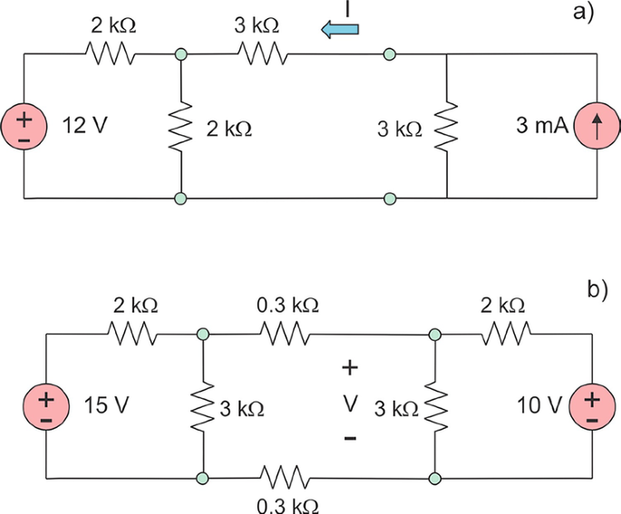
Problem 3.67
Solve the circuits shown in the figure that follows (find current I and show units) using superposition theorem.

Problem 3.68
Find current I (show units) using the superposition theorem.

Problem 3.69
Find current I (show units) using the superposition theorem.

Problem 3.70
-
(a)
Find current I (make sure to show units) using the superposition theorem.
-
(b)
Find voltage V (make sure to show units) using the superposition theorem.

Problem 3.71
For the circuit shown in the figure, determine the absolute voltage (versus chassis ground) and the electric current at the circuit point a.

Problem 3.72
Determine the absolute voltage (versus chassis ground) and the current i at the circuit point a.

Problem 3.73
For the circuit shown in the figure that follows, find the current across the 10 Ω resistance. Show its direction in the figure.

Problem 3.74
Determine the unknown current I in the circuit (solve the problem by superposition).

Problem 3.75
Determine the unknown current I in the circuit (solve the problem by superposition).

3.3.3 Y (Wye) and Δ (Delta) Networks: Use of Superposition
3.3.4 T and Π Networks: Two-Port Passive Networks
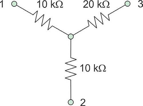
Problem 3.76
Convert the network shown in the figure that follows from Y to Δ:
-
A.
Draw the corresponding Δ network.
-
B.
Label its terminals.
-
C.
Determine and label the corresponding resistance values in the figure.

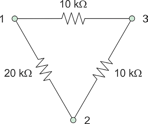
Problem 3.77
Convert the network shown in the figure that follows from Δ to Y:
-
A.
Draw the corresponding Y network.
-
B.
Label its terminals.
-
C.
Determine and label the corresponding resistance values.

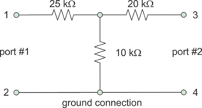
Problem 3.78
Convert the two-port network shown in the figure that follows from T to Π:
-
1.
Draw the corresponding Π network.
-
2.
Label its terminals and ports.
-
3.
Determine and label the corresponding resistance values.

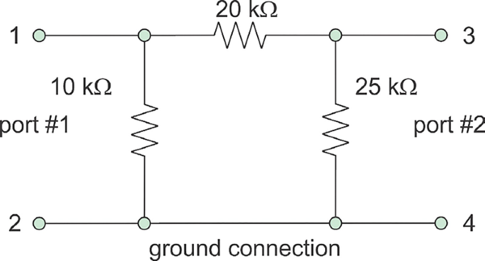
Problem 3.79
Convert the two-port network shown in the figure that follows from Π to T:
-
A.
Draw the corresponding T network.
-
B.
Label its terminals and ports.
-
C.
Determine and label the corresponding resistance values.

Problem 3.80
For the bridge network, determine the equivalent resistance between terminals a and b.

Rights and permissions
Copyright information
© 2019 Springer Nature Switzerland AG
About this chapter

Cite this chapter
Makarov, S.N., Ludwig, R., Bitar, S.J. (2019). Circuit Laws and Networking Theorems. In: Practical Electrical Engineering. Springer, Cham. https://doi.org/10.1007/978-3-319-96692-2_3
Download citation
DOI: https://doi.org/10.1007/978-3-319-96692-2_3
Published:
Publisher Name: Springer, Cham
Print ISBN: 978-3-319-96691-5
Online ISBN: 978-3-319-96692-2
eBook Packages: EngineeringEngineering (R0)