
Abstract
Knowledge of complex arithmetic
Access this chapter
Tax calculation will be finalised at checkout
Purchases are for personal use only
Author information
Authors and Affiliations
Problems
Problems
1.1 12.1 Ideal Transformer as a Linear Passive Circuit Element
12.1.2 Ideal Open-Circuited Transformer : Faraday’s Law of Induction
Problem 12.1
The following figure shows two open-circuited coils subject to a time-varying flux, Φ(t), in the core.

Faraday’s law does not explicitly say anything about the polarity of the induced voltage in the coils. Nevertheless, the induced voltage does have a preferred polarity determined by Lenz’s law (Heinrich Friedrich Emil Lenz (1804–1865), a Russian physicist of German ethnicity, taught at the University of St. Petersburg). Lenz’s Law states that the circuit current due to induced voltage υ produces a flux in such a direction as to oppose the change of the flux. In other words, the induced current always seeks to maintain the status quo of the magnetic field. To find the direction of the anticipated circuit current, you may imagine a resistance connected across the coil terminals. Now, assume that the magnetic flux in the core, Φ, is increasing in time. Label the polarity of the induced voltages for coils #1 and #2, respectively, by ± and show the direction of the anticipated circuit current.
Problem 12.2
Are the following figures correct?

Problem 12.3
For the circuit shown in the following figure, determine voltage υ2(t) if \( \upsilon (t)=100\cos \omega \kern0.1em t\kern0.5em \left[\mathrm{V}\right] \) using Faraday’s law of induction. Count the number of turns. Assume no flux leakage.

Problem 12.4
For the circuit shown in the figure below, determine voltage υ2(t) if\( \upsilon (t)=70\cos \omega \kern0.1em t\kern0.5em \left[\mathrm{V}\right] \) using Faraday’s law of induction. Count the number of turns. Assume no flux leakage.

Problem 12.5
Explain the meaning of the ideal magnetic core. What is the inductance value for an inductor which uses the closed-loop ideal magnetic core?
Problem 12.6
You are given the source voltage in the form \( {\upsilon}_{\mathrm{S}}(t)=340\cos \left(2\pi 60t\right)\kern0.5em \left[\mathrm{V}\right] \), the number of turns of primary winding \( {N}_1=250 \), the finite relative permeability of the magnetic core, \( {\mu}_{\mathrm{r}}=7000 \), the coil length of the primary winding of 9 cm, and the core cross section of \( A=0.0015\kern0.5em {\mathrm{m}}^2 \).
-
A.
Find the exciting current iΦ(t) (no-load current) in the primary winding of this nonideal transformer.
-
B.
Reduce N1 by the factor of 10 and repeat the solution.
12.1.4 Ampere’s Law
12.1.5 Ideal Loaded Transformer
12.1.6 Ideal Transformer Versus Realistic Transformer: Transformer Terminology
Problem 12.7
For the circuit shown in the following figure, establish the relation between currents i1(t) and i2(t). Assume the ideal magnetic core. Count the number of turns.

Problem 12.8
For the circuit shown in the following figure, establish the relation between currents i1(t), i2(t), and i3(t). Assume an ideal magnetic core. Count the number of turns.

Problem 12.9
For the circuit shown in the figure below, determine current i2(t) given that \( {i}_1(t)=1\cos \omega \kern0.1em t\kern0.5em \left[\mathrm{A}\right] \). Count the number of turns.

Problem 12.10
For the circuit shown in the figure below, establish the relation between currents i1(t), i2(t), and i3(t). Assume an ideal magnetic core. Count the number of turns. Hint: Ampere’s law for the ideal core applies to every closed path.

Problem 12.11
In Problem 12.6, determine the instantaneous stored energy of a nonideal transformer given a core centerline length of 30 cm.
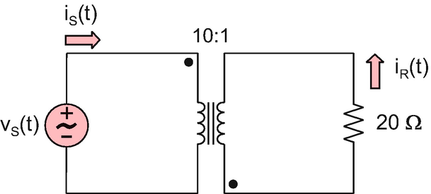
Problem 12.12
In the circuit shown in the figure below, \( {\upsilon}_{\mathrm{S}}(t)=170\cos \left(2\pi 60t\right)\kern0.5em \left[\mathrm{V}\right] \). For a 100 Ω resistive load, determine:
-
Source current iS(t)
-
Load voltage υR(t)
-
Load current iR(t)
-
Average power delivered to the load P
when the turns ratio is equal to 10:1, 1:1, and 1:10.

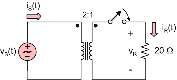
Problem 12.13
In the circuit shown in the figure below, \( {\upsilon}_{\mathrm{S}}(t)=325\cos \left(2\pi \omega t\right)\kern0.5em \left[\mathrm{V}\right] \). The ideal transformer model is used. Determine source current iS(t), load voltage υR(t), and load current iR(t) when:
-
A.
The switch is open.
-
B.
The switch is closed.
-
C.
The switch is closed and \( \omega \to 0 \).

Problem. 12.14
In the circuit shown in the figure below, the current through resistance is given by \( {i}_{\mathrm{R}}(t)=50\cos \left(2\pi 60t\right)\kern0.5em \left[\mathrm{A}\right] \). Determine:
-
Source voltage υS(t)
-
Source current iS(t)

Problem 12.15
A power transformer is rated as 100 kVA, 11,000:2200 V, 60 Hz. Determine:
-
Transformer type
-
Turns ratio
-
The rated current on the low-voltage side
Problem 12.16
Repeat the previous problem for a transformer rated as 10 kVA, 2300:230 V, 60 Hz.
Problem 12.17
Repeat Problem 12.15 for a transformer rated as 2 kVA, 230:115 V, 50 Hz.
1.2 12.2 Analysis of Ideal-Transformer Circuits
12.2.1 Circuit with a Transformer in the Phasor Form
12.2.2 Referred (or Reflected) Source Network in the Secondary Side
12.2.3 Referred (or Reflected) Load Impedance in the Primary Side
Problem 12.18
The load impedance is \( 12.5-j2.5\kern0.5em \Omega \). Find the equivalent impedance of the load ZT combined with a 2:1 step-down transformer in the primary side.
Problem 12.19
Source voltage is given by\( {\upsilon}_{\mathrm{S}}(t)=2.5\cos \omega t+{45}^{{}^{\circ}}\kern0.5em \left[\mathrm{V}\right] \) and the source impedance is \( 5-j0.5\kern0.5em \Omega \). Find the equivalent circuit of the source (find VT and ZT) combined with a 1:4 step-up transformer in the secondary side. Express your result both in frequency domain and in time domain.
Problem 12.20
A large capacitance value of 1.6 mF is required. The available physical component is a 100-μF capacitor. You are given an ideal transformer with an arbitrary turns ratio. Design the equivalent circuit for the 1.6 mF capacitance, specify the transformer turns ratio, and draw the corresponding circuit diagram.
Problem 12.21
For the circuit shown in the figure below, determine transformer’s turns ratio.

Problem 12.22
For the circuit shown in the following figure, \( {\mathbf{V}}_{\mathrm{S}}=10\angle {45}^{{}^{\circ}}\kern0.5em \left[\mathrm{V}\right] \), \( {\mathbf{Z}}_{\mathrm{S}}=5+j5\kern0.5em \Omega \), \( {\mathbf{Z}}_{\mathrm{L}}=5+j5\kern0.5em \Omega \), and \( {N}_1:{N}_2=1:2 \). Find phasor voltage across the load, VL. Express your result in polar form. Assume the ideal transformer.

Problem 12.23
In the circuit shown in the figure below, \( {\upsilon}_{\mathrm{S}}(t)=2.5\cos \left(\omega \kern0.1em t+{45}^{{}^{\circ}}\right)\kern0.5em \left[\mathrm{V}\right] \) where \( \omega =1000\mathrm{rad}/\mathrm{s} \), \( C=10\kern0.5em \upmu \mathrm{F} \), \( {R}_1=25\kern0.5em \Omega \), \( {R}_{\mathrm{L}}=200\kern0.5em \Omega \). Furthermore, \( {N}_1:{N}_2=1:2 \). Find voltage across the load υL(t) in time domain. Assume the ideal transformer.

Problem 12.24
For the circuit shown in the following figure, \( {\mathbf{V}}_{\mathrm{S}}=10\angle {45}^{{}^{\circ}}\kern0.5em \left[\mathrm{V}\right] \), \( {\mathbf{Z}}_{\mathrm{S}}=5+j5\kern0.5em \Omega \), \( {\mathbf{Z}}_{\mathrm{L}}=5+j5\kern0.5em \Omega \), and \( {N}_1:{N}_2=1:2 \). Find phasor current of the source, IS. Express your result in polar form. Assume the ideal transformer.

Problem 12.25
In the circuit shown in the following figure, \( {\upsilon}_{\mathrm{S}}(t)=2.5\cos \left(\omega \kern0.1em t+{45}^{{}^{\circ}}\right)\kern0.15em \left[\mathrm{V}\right] \) where \( \omega =2000\kern0.5em \mathrm{rad}/\mathrm{s} \), \( C=10\kern0.5em \upmu \mathrm{F} \), \( {R}_1=50\kern0.5em \Omega \), \( {R}_{\mathrm{L}}=20\kern0.5em \Omega \). Furthermore, \( {N}_1:{N}_2=2:1 \). Find source current iS(t) in time domain. Assume the ideal transformer.

12.2.4 Transformer as a Matching Circuit
Problem 12.26
A 16-Ω load is connected to an AC voltage source with a voltage amplitude of 10 V and series resistance of 1 Ω. A matching transformer is used with the turns ratio N1 : N2. Determine the average power delivered to the load when
-
A.
$$ {N}_1:{N}_2=1:1 $$
-
B.
$$ {N}_1:{N}_2=1:2 $$
-
C.
$$ {N}_1:{N}_2=1:4 $$
-
D.
$$ {N}_1:{N}_2=1:5 $$
Problem 12.27
A passive RFID tag circuit measuring temperature is modeled by a load resistance of 16 Ω. The tag is wirelessly powered; it is augmented with a small collecting antenna, which has the radiation resistance of \( 1-j2\kern0.5em \Omega \). The negative antenna reactance is an inherent part of the small dipole antenna design. Find the ratio of the average received powers from the antenna with and without the matching transformer. Assume the load matching condition for the real part of the impedances.

Problem 12.28
The previous problem may be generalized as follows. An antenna operates as an energy-harvesting source. The antenna is modeled as an impedance \( {\mathbf{Z}}_{\mathrm{S}}={R}_{\mathrm{S}}+j{X}_{\mathrm{S}} \) in series with a fixed ideal voltage source. The nonzero antenna reactance is an inherent part of the small antenna design. The load is modeled as a resistance RL. Express the turns ratio of a matching transformer, which is necessary for maximum average power transfer from the antenna to the load, in terms of three given problem parameters. Note that this problem has an elegant analytical solution.
12.2.5 Application Example: Electric Power Transfer via Transformers
Problem 12.29
The performance of a transmission line circuit in the following figure is to be analyzed, with and without 1:10 step-up transformer and 10:1 step-down transformer, respectively. All phasors are given in terms of the rms values. Solve the circuit with and without transformers and fill out the table that follows including active load power \( {P}_{\mathrm{L}}=\operatorname{Re}\left({\mathbf{V}}_{\mathrm{L}}\cdot {{\mathbf{I}}_{\mathrm{L}}}^{\ast}\right) \), active source power, \( {P}_{\mathrm{S}}=\operatorname{Re}\left({\mathbf{V}}_{\mathrm{S}}\cdot {{\mathbf{I}}_{\mathrm{S}}}^{\ast}\right) \), and the line power loss \( {P}_{\mathrm{loss}}=R{\left|{\mathbf{I}}_{\mathrm{line}}\right|}^2 \). All powers are to be reported in watts. You are given \( {\mathbf{Z}}_{\mathrm{L}}=4+j2\kern0.5em \Omega \).

Param. | V S | I S | P S | I line |
No tr. | \( 240\angle {0}^{{}^{\circ}} \) | |||
W tr. | \( 240\angle {0}^{{}^{\circ}} \) | |||
Param. | P loss | V L | I L | P L |
No tr. | ||||
W tr. |
Problem 12.30
Repeat the previous problem when the transformer setup changes to a 1:5 step-up transformer and a 5:1 step-down transformer.
Problem 12.31
An AC-direct micro-hydropower system is illustrated in the following figure.

Reprinted from Micro-Hydropower Systems Canada 2004, ISBN 0-662-35880-5
The system uses a single phase induction generator with the rms voltage of 240 V. The system serves four small houses, each connected to the generator via a separate transmission line with the same length of 3000 m. Each line uses AWG#10 solid aluminum wire with a diameter of 2.59 mm. The house load in every house is an electric range with the resistance of 20 Ω. Determine total active power delivered by the generator, PS, total power loss in the transmission lines, Ploss, and total active useful power, PL:
-
1.
When no transformers are used;
-
2.
When a 1:5 step-up transformer is used in powerhouse and a 5:1 step-down transformer is used at home.
Problem 12.32
Solve the previous problem when the distributed line inductance is additionally taken into account. The inductance per unit length of a two-wire line is given by \( \frac{\mu_0}{\pi}\left(\ln \frac{d}{a}+\frac{1}{4}\right) \) where a is the wire radius and d is the separation distance. Assume the separation distance of 1 m. The operation frequency is 50 Hz.
1.3 12.3 Some useful transformers
12.3.1 Autotransformer
Problem 12.33
A voltage source connected to the primary winding of an ideal step-up autotransformer shown in the following figure has the form \( {\upsilon}_{\mathrm{S}}(t)=5\cos \omega t\kern0.5em \left[\mathrm{V}\right] \). The source current into the dotted terminal is \( {i}_{\mathrm{S}}(t)=10\cos \omega t\kern0.5em \left[\mathrm{A}\right] \). You are given \( {N}_1=200 \), \( {N}_2=50 \). Determine voltage υ2(t) and current i2(t) in the secondary.

Problem 12.34
Solve the previous problem for the circuit shown in the following figure.

Problem 12.35
For the circuit shown in the following figure, \( {\mathbf{V}}_{\mathrm{S}}=100\angle {45}^{{}^{\circ}}\kern0.5em \left[\mathrm{V}\right] \), \( {\mathbf{Z}}_{\mathrm{S}}=5+j5\kern0.5em \Omega \), \( {\mathbf{Z}}_{\mathrm{L}}=5+j5\kern0.5em \Omega \), and \( {N}_1:{N}_2=4:1 \). Find phasor current of the source, IS. Express your result in polar form. Assume the ideal autotransformer.

Problem 12.36
Find the equivalent input impedance, Zin, for two autotransformer circuits shown in the following figure.

12.3.2 Multiwinding Transformer
12.3. 3 Center-Tapped Transformer: Single-Ended to Differential Transformation
Problem 12.37
In the circuit shown in the following figure, \( {N}_1=2{N}_2={N}_3 \). How is the instantaneous power partitioned between the two secondary windings if both of them are terminated into the same load resistances? To answer this question, express both p2(t) and p3(t) in terms of p1(t).

Problem 12.38
In the circuit of the previous problem, \( {N}_1=2{N}_2=2{N}_3 \). How is the instantaneous power partitioned between the two secondary windings if winding #2 is terminated into resistance R and winding #3 is terminated into resistance 3R?
Problem 12.39
Determine the turns ratio for the center-tapped transformer in Fig. 12.13.
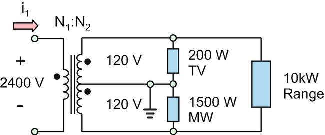
Problem 12.40
A household is using an ideal center-tapped distribution transformer shown in the following figure. All voltage values are the rms values. The resistive loads include a TV, a microwave, and a kitchen range. The powers for every individual load are shown in the figure. Determine:
-
A.
Turns ratio, N1 : N2 of the transformer
-
B.
rms value of input current i1

Problem 12.41
Determine phasor currents IR1, IR2, and IR0 for the center-tapped balanced transformer circuit shown in the following figure. You are given the source phasor voltage \( {\mathbf{V}}_{\mathrm{S}}=10\angle {0}^{{}^{\circ}}\kern0.5em \left[\mathrm{V}\right] \), resistance values \( R=50\kern0.5em \Omega \), and turns ratio \( {N}_1:{N}_2=1 \).

Problem 12.42
Solve the previous problem in a general form, i.e., express phasor currents IR1, IR2, and IR0 in the (generally unbalanced) circuit shown in the following figure in terms of given circuit parameters VS, Z1, Z2, and turns ratio \( a={N}_1:{N}_2 \).

12.3.4 Current Transformer
Problem 12.43
Determine current i2(t) in an ideal current transformer shown in the figure given that \( {i}_1(t)=10\cos \omega \kern0.1em t\left[\mathrm{A}\right] \). Count the number of turns.

1.4 12.4 Real-Transformer Model
12.4.1 Model of a Nonideal Low-Frequency Transformer
12.4.2 Model Parameters and Their Extraction
12.4.3 Analysis of Nonideal Transformer Model
12.4.4 Voltage Regulation and Transformer Efficiency
Problem 12.44
-
A.
Name all seven components of the low-frequency nonideal transformer model.
-
B.
Draw the corresponding circuit diagram.
Problem 12.45
A practical power transformer is characterized by the following nameplate information: 20 kVA 2400:240 V 60 Hz.
-
A.
Determine rated-load phasor voltage VL (show units and assign phase zero).
-
B.
Determine rated-load phasor current IL for power factor of 0.8 lagging (show units).
-
C.
Determine rated-load active power PL (show units).
Problem 12.46
Repeat the previous problem for the power transformer characterized by
2 kVA 230:115 V 50 Hz.
Problem 12.47
A practical power transformer is characterized by the following information:
Element nameplate | 20 kVA 2400:240 V 60 Hz |
Magnetizing reactance \( {X}_{\mathrm{m}}=\omega {L}_{\mathrm{m}} \), Ω | 15,000 |
Core loss resistance, Rc, Ω | 100,000 |
Primary leakage reactance \( {X}_{\mathrm{l}1}=\omega {L}_{\mathrm{l}1} \), Ω | 6.5 |
Secondary leakage reactance, \( {X}_{\mathrm{l}12}=\omega {L}_{\mathrm{l}12} \), Ω | 0.07 |
Primary ohmic resistance R1, Ω | 3.0 |
Secondary ohmic resistance R2, Ω | 0.03 |
Check whether or not equalities (12.38) for the well-designed transformer are satisfied.
Problem 12.48
In a well-designed transformer, the number of turns of both primary and secondary windings is usually quite large. Why is it so? Can we just design a 10:1 transformer with 10 and 1 turns, respectively?
Problem 12.49
The nonideal transformer model is shown in the following figure in frequency domain. Given the rated load with a power factor of 0.8 lagging, determine the source phasor voltage VS and the source phasor current IS for transformer #1 model from Table 12.2.

Problem 12.50
Repeat the previous problem for transformer #2 model from Table 12.2.
Problem 12.51
Repeat Problem 12.49 for transformer #3 model from Table 12.2.
Problem 12.52
The nonideal transformer model is shown in the following figure in frequency domain. Given the rated load with a power factor of 0.7 lagging, determine:
-
A.
Percentage regulation
-
B.
Percentage efficiency
for transformer #1 model from Table 12.2

Problem 12.53
Repeat the previous problem for transformer #2 model from Table 12.2.
Problem 12.54
Repeat Problem 12.52 for transformer #3 model from Table 12.2.
1.5 12.5 Model of Coupled Inductors
12.5.1 Model of Two Coupled Inductors
12.5.2 Analysis of Circuits with Coupled Inductors
12.5.3 Coupling Coefficient
Problem 12.55
Solve a circuit with two coupled inductors in the figure below in frequency domain:
-
A.
Determine the load phasor current and the source phasor current.
-
B.
Determine phasor voltages V1 and V2
given that \( {\mathbf{V}}_{\mathrm{S}}=10\angle {0}^{{}^{\circ}}\kern0.5em \left[\mathrm{V}\right] \) and \( {R}_{\mathrm{L}}=10\kern0.5em \Omega \).

Problem 12.56
Solve the previous problem when the mutual inductance is exactly zero.
Problem 12.57
Solve Problem 12.55 when the mutual reactance is equal to 3 Ω.
Problem 12.58
In the circuit shown in the following figure, determine source phasor current IS given that \( {R}_{\mathrm{L}}=1\kern0.5em \Omega \), \( {R}_{\mathrm{S}}=2\kern0.5em \Omega \), and \( {\mathbf{V}}_{\mathrm{S}}=15\angle {0}^{{}^{\circ}}\kern0.5em \left[\mathrm{V}\right] \).

12.5.4 Application Example: Wireless Inductive Power Transfer
12.5.5 Application Example: Coupling of Nearby Magnetic Radiators
Problem 12.59
Two small coaxial ceramic-core coils with \( {r}_1={r}_2=2.0\kern0.5em \mathrm{cm} \) and with \( {N}_1={N}_2=100 \) are separated by 1 m. What is the voltage signal induced in the second coil (RX) if the current in the first coil (TX) is given by \( {i}_1=100\kern0.5em \mathrm{mA}\times \sin \left(\omega t\right) \)? The operation frequency is 1 MHz.
Problem 12.60
Repeat the previous problem when the operation frequency changes to 10 MHz.
Problem 12.61
In the circuit shown in the following figure, find source phasor current IS in time domain iS(t) given that \( {\upsilon}_{\mathrm{S}}(t)=10\cos \omega t\kern0.5em \left[\mathrm{V}\right] \).

Rights and permissions
Copyright information
© 2019 Springer Nature Switzerland AG
About this chapter

Cite this chapter
Makarov, S.N., Ludwig, R., Bitar, S.J. (2019). Electric Transformer and Coupled Inductors. In: Practical Electrical Engineering. Springer, Cham. https://doi.org/10.1007/978-3-319-96692-2_12
Download citation
DOI: https://doi.org/10.1007/978-3-319-96692-2_12
Published:
Publisher Name: Springer, Cham
Print ISBN: 978-3-319-96691-5
Online ISBN: 978-3-319-96692-2
eBook Packages: EngineeringEngineering (R0)