
Abstract
Knowledge of complex arithmetic
Access this chapter
Tax calculation will be finalised at checkout
Purchases are for personal use only
Author information
Authors and Affiliations
Problems
Problems
1.1 11.1 AC Power Types and Their Meaning
11.1.1 Instantaneous AC Power
11.1.2 Time-Averaged AC Power
Problem 11.1
An AC voltage signal across a resistive load with R = 10 Ω is given by:
-
A.
\( \upsilon (t)={V}_{\mathrm{m}}\cos 1000\kern0.1em t\kern0.5em \left[\mathrm{V}\right] \)
-
B.
\( \upsilon (t)={V}_{\mathrm{m}}\sin 60t\kern0.5em \left[\mathrm{V}\right] \)
-
C.
\( \upsilon (t)={V}_{\mathrm{m}}\cos \left(60t+{45}^{{}^{\circ}}\right)\kern0.5em \left[\mathrm{V}\right] \)
where \( {V}_{\mathrm{m}}=10\kern0.5em \mathrm{V} \). Determine the average AC power into the load in every case.
Problem 11.2
An alternating current through a resistive load with R = 100 Ω is given by:
-
A.
\( i(t)={I}_{\mathrm{m}}\cos {10}^6\kern0.1em t\kern0.5em \left[\mathrm{V}\right] \)
-
B.
\( i(t)={I}_{\mathrm{m}}\cos 37t\kern0.5em \left[\mathrm{V}\right] \)
-
C.
\( i(t)={I}_{\mathrm{m}}\sin \left(2011t+{45}^{{}^{\circ}}\right)\kern0.5em \left[\mathrm{V}\right] \)
where \( {I}_{\mathrm{m}}=1\kern0.5em \mathrm{A} \). Determine the average AC power into the load in every case.
Problem 11.3
An rms voltage across a resistive load with R = 100 Ω is given by:
-
A.
\( {V}_{\mathrm{rms}}=5\kern0.5em \mathrm{V} \)
-
B.
\( {V}_{\mathrm{rms}}=100\kern0.5em \mathrm{V} \)
-
C.
\( {V}_{\mathrm{rms}}=0\kern0.5em \mathrm{V} \)
Determine the average power into the load in every case.
Problem 11.4
An rms current through a resistive load with R = 1 kΩ is given by:
-
A.
\( {I}_{\mathrm{rms}}=1\kern0.5em \mathrm{A} \)
-
B.
\( {I}_{\mathrm{rms}}=100\kern0.5em \upmu \mathrm{A} \)
-
C.
\( {I}_{\mathrm{rms}}=0\kern0.5em \mathrm{A} \)
Determine the average power into the load in every case.
Problem 11.5
An AC voltage signal is given by:
-
A.
\( \upsilon (t)={V}_{\mathrm{m}}\cos \left(\omega \kern0.1em t+\varphi \right)\kern0.5em \left[\mathrm{V}\right] \)
-
B.
\( \upsilon (t)=1\kern0.1em \mathrm{V}+{V}_{\mathrm{m}}\cos \left(\omega \kern0.1em t+\varphi \right)\kern0.5em \left[\mathrm{V}\right] \)
-
C.
\( \upsilon (t)=1\kern0.5em \mathrm{V}-{V}_{\mathrm{m}}\sin \left(\omega \kern0.1em t+\varphi \right)\kern0.1em \left[\mathrm{V}\right] \)
where \( {V}_{\mathrm{m}}=1\kern0.5em \mathrm{V} \), \( \omega =100\kern0.5em \mathrm{rad}/\mathrm{s} \), and \( \varphi =\pi /2\kern0.5em \mathrm{rad} \). Find the time-average voltage \( \overline{\upsilon (t)} \) in every case.
Problem 11.6
Present a mathematical proof of the fact that the expression for the average power, \( P=\frac{V_{\mathrm{m}}^2}{2R} \), holds for an AC voltage signal given by \( \upsilon (t)={V}_{\mathrm{m}}\cos \left(\omega t+\varphi \right)\kern0.1em \left[\mathrm{V}\right] \) where φ is an arbitrary phase.
11.1.3 Application Example: rms Voltages and AC Frequencies Around the World
Problem 11.7
A 100 Ω resistive load is connected to an AC wall plug in:
-
A.
Peoples Republic of China
-
B.
India
-
C.
USA
-
D.
Germany
Determine the average power delivered to the load in every case. Also determine the rms load current in every case.
Problem 11.8
What do you think is a major
-
A.
Advantage
-
B.
Disadvantage
of having a higher AC voltage?
11.1.4 rms Voltages for Arbitrary Periodic AC Signals
Problem 11.9
Determine the average power delivered to a 100 Ω resistive load when the applied periodic voltage signal has the form \( \upsilon (t)=\left(5t+0.01\right)/T\kern0.5em \left[\mathrm{V}\right] \) over one period T = 0.01 s. This signal is known as the sawtooth or the triangular wave:
-
A.
Use the analytical calculation of the rms voltage.
-
B.
Use the rms voltage found numerically, based on a MATLAB script or any software of your choice.
Problem 11.10
Determine the average power delivered to a 100 Ω resistive load when the applied periodic voltage has the form \( \upsilon (t)=\sqrt{t}/T\kern0.5em \left[\mathrm{V}\right] \) over one period T = 0.01 s:
-
A.
Use the analytical calculation of the rms voltage.
-
B.
Use the rms voltage found numerically, based on a MATLAB script or any software of your choice.
Problem 11.11
Of the two periodic voltage signals shown in the figures below,

which signal delivers more average power into a resistive load? The periodic voltage on the top graph is the cosine function. Explain your answer and provide an analytical proof (find the rms voltages and the average power in every case).
Problem 11.12
Of the two periodic signals shown in the figures that follow, which signal delivers more average power into a resistive load? Explain your answer and provide:
-
A.
An analytical proof—find the rms voltage and the average power in every case
-
B.
A numerical proof (use MATLAB or any software of your choice).
The periodic voltage on the top graph is the cosine function. The periodic voltage on the bottom graph is given by \( \upsilon (t)=3.2\times {10}^5{\left(t-0.005\right)}^2-4\kern0.5em \left[\mathrm{V}\right] \) over the time interval from 0 to T.

Problem 11.13
Of the two periodic signals shown in the figure that follows, which signal delivers more average power into a resistive load? The periodic voltage on the top graph is the cosine function. Explain your answer and provide:
-
A.
An analytical proof—find the rms voltage and the average power in every case
-
B.
A numerical proof (use MATLAB or any software of your choice).

11.1.5 Average AC Power in Terms of Phasors: Power Angle
11.1.6 Average Power for the Resistor, Capacitor, and Inductor
Problem 11.14
The phasor voltage across a purely resistive load with the resistance R = 100 Ω is given by \( \mathbf{V}=-2-j1.5\kern0.75em \left[\mathrm{V}\right] \). Find the average power delivered to the load.
Problem 11.15
The phasor current through a purely resistive load with the resistance R = 100 Ω is given by \( \mathbf{I}=-1-j0.5\kern0.75em \left[\mathrm{A}\right] \). Find the average power delivered to the load.
Problem 11.16
The phasor voltage across an AC load and the phasor current through the same AC load are given by:
-
A.
Find the average power delivered to the load analytically.
-
B.
Find the average power delivered to the load numerically using MATLAB or any software of your choice.
Problem 11.17
Repeat the previous problem for phasor voltage and phasor current in the form:
Problem 11.18
Express the average power given by \( P=\frac{\operatorname{Re}\left(\mathbf{V}\cdot {\mathbf{I}}^{\ast}\right)}{2} \) in terms of the following three quantities: magnitude of the phasor voltage, |V|; the impedance magnitude, |Z|; and the real part of the impedance, Re(Z).
Problem 11.19
Determine the average power delivered to the load circuit between terminals a and b shown in the figure that follows. The AC angular frequency is 100 rad/s.

Problem 11.20
Determine the average power delivered to the load circuit between terminals a and b shown in the figure that follows. The AC angular frequency is 1000 rad/s.

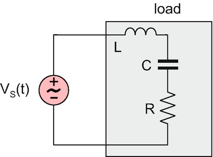
Problem 11.21
Determine the average power delivered to the load circuit shown in the figure below. The AC signal frequency is 106 Hz.

11.1.7. Average Power, Reactive Power, and Apparent Power
11.1.8. Power Triangle
Problem 11.22
Determine the resistance and the reactance of the circuit blocks (the load) shown in the figure. The AC angular frequency is 1000 rad/s.

Problem 11.23
Determine the resistance and the reactance of the circuit block (the load) shown in the figure in terms of R, L, and C in a general form. The AC angular frequency is ω.

Problem 11.24
Write the expressions (and show units) for the average power P and the reactive power Q in terms of:
-
A.
Phasor current I through the load and the load resistance R and the reactance X
-
B.
Phasor voltage V across the load, the load impedance magnitude |Z|, and the impedance phase (or the power angle) θ
Problem 11.25
For the circuit shown in the figure with the parameters \( {\displaystyle \begin{array}{l}{V}_{\mathrm{m}}=170\kern0.5em \mathrm{V},\omega =377\kern0.5em \mathrm{rad}/\mathrm{s},\\ {}L=26.5\kern0.5em \mathrm{mH},\kern1em R=25\kern0.5em \Omega \end{array}} \):
-
A.
Determine the power angle and the power factor.
-
B.
Determine the average (or true) power and the reactive power for the inductive load shown in the figure.
-
C.
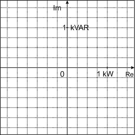
Construct the corresponding power triangle.


Problem 11.26
For the circuit shown in the figure with the parameters \( {V}_{\mathrm{m}}=170\kern0.5em \mathrm{V},\omega =377\kern0.5em \mathrm{rad}/\mathrm{s},C=500\kern0.5em \upmu \mathrm{F},\kern1em R=10\kern0.5em \Omega \):
-
A.
Determine the power angle and the power factor.
-
B.
Determine the average (or true) power and the reactive power for the capacitive load shown in the figure.
-
C.
Construct the corresponding power triangle.

Problem 11.27
For the circuit shown in the figure with the parameters \( {V}_{\mathrm{m}}=170\kern0.3em \mathrm{V},\kern3pt \omega =377\kern0.3em \mathrm{rad}/\mathrm{s},\kern3pt L=14.07\kern0.35em \mathrm{mH},C=500\kern0.5em \upmu \mathrm{F},R=10\kern0.5em \Omega \):
-
A.
Determine the power angle and the power factor.
-
B.
Determine the average (or true) power and the reactive power for the complex load shown in the figure.
-
C.
Construct the corresponding power triangle.


1.2 11.2 Power Factor Correction: Maximum Power Efficiency and Maximum Power Transfer
11.2.1 Power Factor Correction
11.2.3 Principle of Maximum Power Efficiency for AC Circuits
Problem 11.28
Correct the power factor for the inductive load shown in the figure below. The circuit parameters are \( {V}_{\mathrm{m}}=170\kern0.5em \mathrm{V},\omega =377\kern0.5em \mathrm{rad}/\mathrm{s} \) and \( L=53\kern0.5em \mathrm{mH},R=10\kern0.5em \Omega \):
-
A.
Present the circuit diagram of the modified load and determine the required capacitance.
-
B.
Determine average (true) power, reactive power, power factor, and amplitude of the circuit current before the power factor correction.
-
C.
Determine average (true) power, reactive power, power factor, and amplitude of the circuit current after the power factor correction.

Problem 11.29
Correct the power factor for the capacitive load shown in the figure that follows. The circuit parameters are \( {V}_{\mathrm{m}}=170\ \mathrm{V},\kern1em \omega =377\kern0.5em \mathrm{rad}/\mathrm{s} \) and \( C=265\kern0.5em \upmu \mathrm{F},\kern1em R=10\kern0.5em \Omega \):
-
A.
Present the circuit diagram of the modified load and determine the required inductance.
-
B.
Determine average (true) power, reactive power, power factor, and amplitude of the circuit current before the power factor correction.

Problem 11.30
A whip monopole antenna used in US Coast Guard ships has an equivalent electric circuit shown in the figure of the previous problem. Its (radiation) resistance is 1 Ω, and the reactance is −j1000 Ω. By modifying the antenna circuit with a lumped inductor, it is required to make the antenna impedance real and as large as possible:
-
A.
Present the circuit diagram of the modified load
-
B.
Determine the required impedance of the inductor.
11.2.4 Principle of Maximum Power Transfer for AC Circuits
Problem 11.31
Describe in your own words the difference between the concepts of maximum power efficiency and maximum power transfer for AC circuits.
Problem 11.32
A generator’s impedance is \( 50\angle {30}^{{}^{\circ}}\kern1em \left[\Omega \right] \). What should the load impedance be to allow the maximum power transfer to the load?
Problem 11.33
-
A.
A generator’s impedance is 50 Ω. The load impedance is 1 + j50 [Ω]. What percentage of the maximum available power (at the load impedance of 50 Ω) is transferred to the load?
-
B.
Repeat the same task for the load impedance of 1 − j50 [Ω].
-
C.
Repeat the same task for the load impedance of 5 + j50 [Ω].
Hint: Derive the general expression for the power ratio first and then plug in the numbers.
1.3 11.3 AC Power Distribution: Balanced Three-Phase Power Distribution System
11.3.1 AC Power Distribution Systems
11.3.2 Phase Voltages : Phase Sequence
Problem 11.34
Draw generic circuits for the following representative AC power distribution systems:
-
A.
Single-phase two-wire system
-
B.
Single-phase three-wire system
-
C.
Two-phase three-wire system
-
D.
Three-phase four-wire system
Show loads and phasor voltages with the corresponding phases.
Problem 11.35
Determine the phase sequence for the phase voltages given by:
To simplify the solution, construct the corresponding phasor diagram in the figure below:

Problem 11.36
Given \( {\mathbf{V}}_{\mathrm{bn}}=120\angle {45}^{{}^{\circ}}\left[\mathrm{V}\right] \), find Van and Vcn assuming:
-
A.
The positive abc phase sequence
-
B.
The negative acb phase sequence
Express your result in phasor form. Make sure that the phase ranges from −180° to +180°. To check the solution, you may want to use the corresponding phasor diagram shown in the figure for the previous problem.
11.3.3 Wye (Y) Source and Load Configurations for Three-phase Circuits
11.3.4 Application: Examples of Three-phase Source and the Load
11.3.5 Solution for the Balanced Three-Phase Wye-Wye Circuit
11.3.6 Removing the Neutral Wire in Long-Distance Balanced High-power Transmission
Problem 11.37
-
A.
Draw the circuit diagram for a generic three-phase four-wire balanced wye-wye power distribution system.
-
B.
Label phase voltages and phase impedances ( load impedances per phase).
-
C.
Label line currents.
Problem 11.38
A three-phase circuit is shown in the figure that follows:
-
A.
Is it a balanced wye-wye circuit?
-
B.
If not, show your corrections on the figure.

Problem 11.39
Repeat the previous problem for the circuit shown in the figure below:

Problem 11.40
Repeat Problem 11.38 for the circuits shown in the figure that follows:

Problem 11.41
Prove that Eq. (11.28) of this chapter for line voltages also holds for the negative phase sequence to within the substitution \( {30}^{{}^{\circ}}\to -{30}^{{}^{\circ}} \).
Problem 11.42
The local electric service in the European Union is provided by a three-phase four-wire abcn wye system with the line voltages equal to 400 V rms each (so-called Niederspannungsnetz):
-
A.
Determine the rms phase voltages.
-
B.
By connecting terminals abcn in any sequence of your choice, could you in principle obtain the rms voltages higher than 400 V?
Problem 11.43
Determine line currents in the balanced three-phase wye-wye circuit shown in the figure that follows. You are given the acb sequence of phase voltages \( {\mathbf{V}}_{\mathrm{an}}=170\angle {0}^{{}^{\circ}}\kern0.5em \left[\mathrm{V}\right] \), \( {\mathbf{V}}_{\mathrm{bn}}=170\angle {120}^{{}^{\circ}}\kern0.35em \left[\mathrm{V}\right] \), \( {\mathbf{V}}_{\mathrm{bn}}=170\angle -{120}^{{}^{\circ}}\kern0.35em \left[\mathrm{V}\right] \), and load impedance per phase, \( \mathbf{Z}=8 + j30\kern0.5em \Omega \).
Plot phasor currents on the phasor diagram that follows.


Problem 11.44
In the balanced three-phase wye-wye circuit shown in the figure that follows, the power line resistance and inductance are additionally included into consideration. The three-phase source operates at 60 Hz; \( R=2\kern0.5em \Omega \), \( L=9.6\kern0.5em \mathrm{mH} \). You are given the abc sequence of phase voltages \( {\mathbf{V}}_{\mathrm{an}}=170\angle {0}^{{}^{\circ}}\kern0.1em \left[\mathrm{V}\right] \), \( {\mathbf{V}}_{\mathrm{bn}}=170\angle -{120}^{{}^{\circ}}\left[\mathrm{V}\right] \), \( {\mathbf{V}}_{\mathrm{bn}}=170\angle {120}^{{}^{\circ}}\kern0.5em \left[\mathrm{V}\right] \), and load impedance per phase, \( \mathbf{Z}=7+j30\kern0.5em \Omega \).
-
A.
Determine line currents.
-
B.
Plot phasor line currents on the phasor diagram to the previous problem.

1.4 11.4 Power in Balanced Three-Phase Systems: Delta-connected Three-Phase Circuits
11.4.1 Intantaneous Power
11.4.2 Average Power, Reactive Power, and Apparent Power
Problem 11.45
In a three-phase balanced wye-wye system, the rms phase voltages are 120 V, and the rms line currents are 10 A. The impedance has the power angle of \( \theta ={75}^{{}^{\circ}} \). Find:
-
1.
The instantaneous load power
-
2.
The average load power
Problem 11.46
In a three-phase balanced wye-wye system, the rms line voltages are 400 V, and the rms line currents are 10 A. The impedance has the power angle of \( \theta ={60}^{{}^{\circ}} \). Find:
-
1.
The instantaneous load power
-
2.
The average load power
Problem 11.47
In the three-phase system shown in the figure that follows, \( \mathbf{Z}=40\angle {60}^{{}^{\circ}} \). The sources have the relative phases \( 0,\kern0.5em -{120}^{{}^{\circ}},\kern0.5em +{120}^{{}^{\circ}} \). The rms line voltages are 208 V. Determine:
-
A.
The type of the three-phase system
-
B.
Instantaneous power delivered to the three-phase load
-
C.
Average power delivered to the three-phase load

Problem 11.48
A balanced wye-wye three-phase system in the figure that follows uses lossless transmission lines and operates at 60 Hz. The line-to-neutral voltages have the amplitudes of 170 V, \( {V}_{\mathrm{m}}=170\kern0.5em \mathrm{V} \). Every phase impedance is a 92-mH inductance in series with a 20 Ω resistance. Find the instantaneous load power.

Problem 11.49
In the previous problem:
-
A.
Determine the load average power, reactive power, and the apparent power.
-
B.
Do these powers coincide with the corresponding source measures?
Problem 11.50
A three-phase induction motor is modeled by a balanced wye load. The motor (active) power is 2.5 kW; the line current is 10 A rms, and the phase voltage of a three-phase wye source is 120 V rms. Determine the power factor of the motor.
Problem 11.51
In the previous problem, the motor (active) power is 9 kW; the line current is 15 A rms, and the line voltage of a three-phase wye source is 400 V rms. Determine the power factor of the motor.
11.4.4 Balanced Delta-Connected Load
11.4.5 Balanced Delta-Connected Source
Problem 11.52
A three-phase balanced wye-wye system is shown in the figure that follows. Its delta-delta equivalent is sought, which is shown in the same figure. For the delta-delta system, write the corresponding voltage and impedance values in the phasor form close to every circuit element.

Problem 11.53
A three-phase balanced delta-delta system is shown in the figure that follows. Its wye-wye equivalent is sought, which is shown in the same figure. For the wye-wye system, write the corresponding voltage and impedance values in the phasor form close to every circuit element.

Problem 11.54
A balanced delta-delta system shown in the figure below operates at 50 Hz. The phase voltages of the delta source, Vab, Vbc, Vca, have the amplitudes of \( {V}_{\mathrm{m}}=563.4\kern0.5em \mathrm{V} \) each. Every phase impedance is a 0.21 H inductance in series with a 38-Ω resistance:
-
A.
Find the average load power,
-
B.
Find the instantaneous load power,
-
C.
Find the apparent load power.

Problem 11.55
A balanced wye-delta system shown in the figure below operates at 60 Hz. The phase voltages of the wye source, Van, Vbn, Vcn, have the amplitudes of \( {V}_{\mathrm{m}}=170\kern0.5em \mathrm{V} \) each. Each phase impedance is a 0.18 H inductance in series with a 90 Ω resistance:
-
A.
Find the average load power,
-
B.
Find the instantaneous load power,
-
C.
Find the apparent load power.

Rights and permissions
Copyright information
© 2019 Springer Nature Switzerland AG
About this chapter

Cite this chapter
Makarov, S.N., Ludwig, R., Bitar, S.J. (2019). AC Power and Power Distribution. In: Practical Electrical Engineering. Springer, Cham. https://doi.org/10.1007/978-3-319-96692-2_11
Download citation
DOI: https://doi.org/10.1007/978-3-319-96692-2_11
Published:
Publisher Name: Springer, Cham
Print ISBN: 978-3-319-96691-5
Online ISBN: 978-3-319-96692-2
eBook Packages: EngineeringEngineering (R0)