
Abstract
In the development and use of applications, the User Interface (UI) and User experience (UX) has become essential. The well-adjusted UI and UX are the key features to assess the completeness of the application. As the importance of the UI and UX increases, formal representation of the UI and UX become essential. This paper proposes a formal representation method for ICT application. The method models an ICT application using the discrete event formalism. By utilizing the hierarchically and modular features of the discrete event formalism, a developer or UX researcher may utilize the modeling method to represent and assess the UI and UX of the ICT application. As a case study, this research illustrates how to model a website by proposed modeling method. The case study shows the modeling method can capture the essential behavior of the ICT application.
You have full access to this open access chapter, Download conference paper PDF
Keywords
1 Introduction
As the Information, Communication, and Technology (ICT) become essential in daily life, the importance of ICT application is grown in modern society. In modern society, the ICT application has come a familiar tool to the various fields from agriculture to industry [1, 2], and it has become inevitable. As the growth of the ICT application market increase, application developers or service providers launch their ICT application to the ICT markets. However, as the growth of ICT application market increases, various application developers and service providers may mimic the popular ICT application. Therefore, there is various ICT application exists at the ICT market which has the identical functionalities but has a different design. Thus, the User Interface (UI) and User Experience (UX) have become one of the vital factors to the users to choose proper ICT application among the many similar kinds of applications.
In general, the definition of the UX is the overall experience that the users interact with products, services, and systems. Based on the definition of the UX, the UX can be formed from the interaction between a user and a product which includes the hardware and the software. Therefore, to model or assess the UX, a researcher should model a user and a system. Also, the researcher should consider the UI. The UI is the interface between human and the system. For example, when a user wants to navigate to the previous page on the smartphone, the user should touch a button or give specific gestures to the device. The UI is the method to trigger event to the ICT system, and the ICT system may react based on the event. During the interaction between the user and the system, the user may accustom to the UI. Therefore, the UX can be considered as accustomed experience from specific software and specific hardware which forms the UI. For instance, a user who uses iOS device may feel difficult when the user uses the Android device. Since the Android device has a physical back button, the UI of the Android device has different form compared to the iOS device. As a result, when the researcher wants to analyze the UX, the researcher should consider the hardware, software and the behavior of the users at the same time.
To model the characteristics of the hardware, software and the behaviors of the users, many researchers proposed various methods [3,4,5]. To model the characteristics, the researchers may use the natural language or use the graphical representation. For the natural language, researchers describe the characteristics of the UI, hardware specification, or behaviors of the users in the design documents as text or table form. The design documents help a developer and the designers to collaborate with each other to develop the ICT applications. However, the natural language has a critical disadvantage. Since the natural language has ambiguity, the researcher may experience difficulties to analyze the effects of the UI and the behavior of the users. On the other hand, the graphical form utilizes the graphical notations, such as nodes, which represents a state of the system, and arcs, which represents the event trigger. Therefore, the path from an initial state to the given node shows the event sequence of the ICT applications. The problem of the existing method utilizing the graphical notation is that a researcher should model the behavior of a user and the ICT application at the same time. As a result, the researcher should consider the interaction between human and the application and the result of the modeling may be complicated.
This research introduces the hierarchical modeling framework for ICT application to assist measuring the UX using graphical notation. The modeling framework has two components to model the behaviors: the behavior component and association component. The behavior component has two types. The first type of the behavior component models the behavior of the user and other type models the behavior of the application. Each component utilizes the node to represent the state of the system, and the arcs represent the event of the system. For example, when a user wants to navigate to given Uniform Resource Locator (URL) using web browser application on the smartphone, the user may touch the address bar and type the URL. Then, if the user wants to navigate to the previous page, the user may choose to touch the previous icon or the physical back button. To capture the behaviors, the researcher should consider the behavior of the user and the smartphone vendor at the same time. However, the approach of this research separates the hardware behavior and the human behavior. The human behavior of the scenario is that the user triggers the event to navigate to specific URL and navigate back. The physical back button or the previous icon is not essential to the user. The physical back button, the previous icon or the gestures are related to the hardware and the operating system based on the ICT device vendor. Therefore, a researcher may consider the device behaviors based on the hardware and separate them from the graphical notation. Lastly, the association components associate the human behavior model and the system model. The association component simulates the given human behavior model and the system model to analyze the UX. The association component first simulates the human behavior model and send the event to the device model. When the system model receives the event, the device model may choose event transition based on the graphical notation. After that, the device model sends the event to the association component, and the association component relays the events to the human model.
This paper contains five sections. Section 2 describes theoretical backgrounds, UI/UX of ICT application and the Discrete Event System (DEVS) formalism. Section 3 introduces the hierarchical modeling framework based on the DEVS formalism. Section 4 explains how a researcher model the ICT application using the proposed method, and Sect. 5 concludes this paper.
2 Background
2.1 UI/UX of ICT Application
ICT applications have become an essential part of our lives. It includes various types of mobile applications, a personal computer application, and even web services. Since the ICT applications cover various areas, a researcher may not easily define what the ICT application is. However, in general, the ICT application has the following characteristics. First, it is an interactive system; the user and application system exchange and reacts opponent action. Second, ICT applications are made up of segments. Segments work dependently or independently depending on application settings. Third, these segments may or may not respond according to the user input; so, user input is one of the factors considered. Fourth, the segments may or may not respond as time inside changes without input from the user (Fig. 1).

Example of ICT application
UI and UX are essential factors of an ICT application to differentiate with other ICT application. UX represents the overall experience of the perception, response, and behavior that the user thinks and feels as he or she uses a system or product or service directly or indirectly. That is, the design of UX takes into consideration the feelings and experiences one gain from interacting with objects, machines, and software. Even same ICT application may have different UX based on the hardware platform. Since the UI is a medium that allows interaction between the user and the application, the engineer may choose different implementation method to develop the UI of a system. Therefore, developers should express user-conscious UI and UX designs in their development of ICT applications. Otherwise, the app will be shunned by consumers in the application market.
2.2 Discrete Event System Specification
There are many formal methods to model something that happens in real world [7, 8]. Among them, the Discrete Event System (DEVS) formalism is one of the most popular modeling methods to capture the dynamic transition of system’s state by a specific event. The DEVS formalism can describe state transitions as they are transposed through an input event or as time flows internally. This is suitable for modeling ICT applications where the status is transposed by input from the user through the hardware or the status transition by changes in time without input from the user. Second, DEVS formalism decompose a system into small systems using atomic model. When a modeler decomposes a system into non-separable sub-systems, the modeler may use the atomic model to model the non-separable sub-system. The atomic model is used to express the behavior of a system. The coupled model of the DEVS formalism is used to aggregate non-separable sub-system to form a complex system. Therefore, the DEVS formalism is suitable to model a user, the ICT application, and interaction between them [9, 10]. Finally, the DEVS formalism may represent internal state translation based on the time changes, as compared to the Petri-net. The timed transition of the DEVS formalism enables to express state transition by internal time changes without user input, and it is ideal to model ICT application.
The atomic model is a model that describes the behavior characteristics of the system and consists of seven components which are input sets, output sets, status sets, transfer functions that describe the following states of the model, output functions, and time progression functions to produce an output.
-
DEVS-AM = <X, S, Y, S, δext, δint, λ, ta> where
-
X set of internal input events;
-
S set of state;
-
Y set of external output events;
-
δext Q ⨯ X → S, external transition function specifying state transitions based on the external events;
-
δint Q → S, internal transition function specifying state transitions based on the internal events;
-
λ Q → Y, output function generating external events as output;
-
ta S → R0,∞, time advance function.
-
▯ Q = {(s, e) │ s ⊆ S, 0 ≤ e ≤ ta(s)}
-
The coupled model consists of multiple component models, which can be the atomic models or coupled models. With these characteristics, the coupled model can be formed by each component model and the external inputs, output, and connections among internal component models.
-
DEVS-CM = <X, Y, DM, EIC, EIC, EOC, IC, Select>
-
X Set of input events
-
Y Set of output events
-
DM Set of component models of DEVS
-
EIC ⊆ X ⨯ ∪Xi: Coupling connection of external input
-
EOC ⊆ ∪Yi ⨯ Y: S, Coupling connection of external output
-
IC ⊆ ∪Yi ⨯ ∪Xi: Coupling connection of inside
-
Select: 2{DM} – ϕ → DM: Function of selecting one model of multiple models which generate output simultaneously.
-
More detailed description of the DEVS formalism and simulation algorithm can be found in [11].
3 Hierarchical Modeling Framework for ICT Application
As the ICT application can be decomposed into several components and may form a hierarchical structure, this research proposes a modeling rule set to model an ICT application and its behavior at the same time. Based on the modeling rules, ICT applications such as the web service or mobile application can be formally modeled. Each component of the ICT application has states to represent the current status of the ICT application. Then, an arc shows the state transition based on the user-generated event or system event, such as animation, sound, and pop-ups.
To model the ICT application, a modeler should characterize the behavior of an ICT application. To represent the application’s hierarchical structure, the researcher may divide the application into three categories using the proposed method: (1) full screen of the app, (2) specific region in the app, and (3) segments on a particular screen. The full screen of the app holds every component of the application. A specific region of the app is the component for the full screen. The specific region may have various segments of application. Finally, segments on a specific region are the non-separable component of the ICT application, and it may change the behavior of the ICT application. In summary, the full-screen of the ICT application is the frame that holds every component of the ICT application, and specific region is the group that contains segments. The segment is the behavior component that represents the action of the ICT application. Therefore, full-screen and region of the ICT application are structural components of the ICT application. Figure 2 shows the relationship among full-screen, region, and segments of an ICT application.

Example of application hierarchical structure
As shown in the Fig. 2, the outmost rectangular shows the full-screen that holds four regions, and region may hold one or more segments. As the definition of the segment is the components that changes the behavior, a modeler may model button, link, and animated components as segment. To capture the behavior of the ICT application, a modeler may use modeling rules to model the ICT application. Followings are the modeling rules to represent the hierarchical structure and the behavior of the ICT application.
-
ICT application should be decomposed into structural components and behavioral components.
-
Behavioral components should be modeled as the atomic model of the DEVS formalism, and structural components should be modeled as the coupled model.
-
Each behavioral component can be categorized by the functional distinction. Following Fig. 3 shows the classification criteria.
Fig. 3. 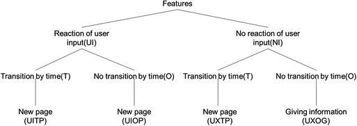
Classification criteria for segments

Based on the classification criteria, a modeler may select a proper pattern of the DEVS model to model the behavior of the segment. For example, the modeler may select modeling pattern; then the modeler may customize the segment by increasing the number of the states to represent the system state.
For UXOG, there is no transition by external input, and there is no transition of the state by any change in time (Fig. 4).

Function model of UXOG
For UXTP, there is no external transition; however, transition with changes in time occurs, resulting in output (Fig. 5).

Function model of UXTP
For UITP, the user input generates a translation. After the occurrence of the user input, the output is processed from the coupled mode, and atomic model takes input after the operation. Based on the input received from the combined mode, atomic model send output to upper model. There is also an internal transition over time (Fig. 6).

Feature model of UITP
For UIOP, the user input generates a translation. After occurrence of the user input, the output is processed from the coupled mode and atomic model takes input after operation. Based on the input received from the Combined mode, atomic model send output to upper model. There is not an internal transition by time changes (Fig. 7).

Feature model of UIOP
In this paper, if the other user input entered after the previous user input generates an output, the sequence is expressed by symbol of ‘→’ using feature name.
4 Case Study
Based on the proposed modeling method, this paper introduces an introductory example, which introduces modeling results of various websites. Two examples of websites will show how to model ICT application. One website is Samsung Display, and the other is Handong Global University. In these cases, they show the modeling results of screen and segment using hierarchical modeling framework (Fig. 8).

Main site of Samsung Display
The main site of Samsung Display is structured like Fig. 9. Except for ④, ① to ⑧ react to user input. Especially, ② reacts two times continuous reaction and enumeration can express it. Then, enumeration can show function inheritance of segment (Fig. 10).

Regions of Samsung Display main site

Main site of Handong Global University
Main site of Handong Global University is structured like Fig. 11. Except ④, ① to ⑦ respond to user input. They inherit no user input and react by only one reaction.

Regions of Handong Global University main site
The two main sites modelled are listed as Figs. 12 and 13. Looking at the two modeled sites, you can see that the structures of the remaining regions are very similar, with the exception of segment ②. In addition, for Samsung display main page, it can strongly simulate the main page of the Handong Global University.

DEVS model of main site of Samsung Display

DEVS model of main site of Handong Global University
The DEVS model of region ② on Samsung display is as follows. There are a total of five segments in region ②. Each segment can be processed on two inputs. That is, within the input model in C1 to C5, there is another model that handles the other inputs. To simplify it visually, it is expressed only on the C1 input model, and the rest of the C2–C5 input models have the same structure as the C1 input model (Fig. 14).

DEVS model of main site region ② of Samsung Display
Main site region ⑦ of Handong Global University has 6 segments and segments have each input model. Unlike Samsung displays, each segment only responds one input and release one output (Fig. 15).

DEVS model of main site region ⑦ of Handong Global University
5 Conclusion
This paper proposed a modeling method and introduced the relationship between hierarchical representations and ICT applications. A formal representation would allow this modeling method to be applied to a wide variety of ICT applications. Using the above model rules, a modeler can review an ICT application by setting up a UX rule and check the developed application that meets the goals of UX. The method would allow developers to deviate from the way in which they previously asked users to assess applications. This will help reduce the cost of the experiment group and assess as soon as possible whether applications have a good design.
References
Chauke, M.: An analysis of the effectiveness/impact of ICTs in dairy production- a case of Zimbabwe’s Mashonaland East’s Beatrice-Mariranwe Dairy Farmers. Graduate dissertation of University of Zimbabwe (2015)
Ghavifekr, S., Afshari, M., Siraj, S., Seger, K.: ICT application for administration and management: a conceptual review. In: 13th International Educational Technology Conference (2013)
Blythe, M., Hassenzahl, M., Law, E.L.-C., Vermeeren, A.P.O.S.: An analysis framework for user experience (UX) studies: a green paper. Towards a UX Manifesto (2007)
Ardito, C., Costabile, M.F., Lanzilotti, R., Montinaro, F.: Towards the evaluation of UX. Towards a UX Manifesto (2007)
Kort, J., Vermeeren, A.P.O.S., Fokker, J.E.: Conceptualizing and measuring UX. Towards a UX Manifesto (2007)
Orlova, M.: User experience design (UX design) in a website development: website redesign. Bachelor’s thesis Information Technology (2016)
Hack, M.: Petri Net Language. Technical report (1976)
Zeigler, B.P.: Multifaceted Modeling and Discrete Event Simulation. Academic Press, Orlando (1984)
Concepcion, A.I., Zeigler, B.P.: DEVS formalism: a framework for hierarchical model development. IEEE Trans. Softw. Eng. 14, 228–241 (1988)
Kim, T.G.: Hierarchical development of model classes in the DEVS-scheme simulation environment (1991)
Zeigler, B.P., Praehofer, H., Kim, T.G.: Theory of Modelling and Simulation, 2nd edn. Academic Press, Cambridge (2000)
Author information
Authors and Affiliations
Corresponding author
Editor information
Editors and Affiliations
Rights and permissions
Copyright information
© 2018 Springer International Publishing AG, part of Springer Nature
About this paper

Cite this paper
Jo, H., Choi, CB. (2018). Hierarchical Modeling Framework for ICT Application to Measure the User Experience. In: Marcus, A., Wang, W. (eds) Design, User Experience, and Usability: Theory and Practice. DUXU 2018. Lecture Notes in Computer Science(), vol 10918. Springer, Cham. https://doi.org/10.1007/978-3-319-91797-9_30
Download citation
DOI: https://doi.org/10.1007/978-3-319-91797-9_30
Published:
Publisher Name: Springer, Cham
Print ISBN: 978-3-319-91796-2
Online ISBN: 978-3-319-91797-9
eBook Packages: Computer ScienceComputer Science (R0)