
Abstract
Each business process management (BPM) approach requires a precise semantic specification scheme. Semantically, ambiguities can cause a lot of problems during the lifespan of a business process. As Abstract State Machines (ASMs) are grounded to subject orientation, we have explored their capabilities with respect to representing and executing Subject-oriented BPM (S-BPM) models. Based on the ASM method we implemented an interpreter which allows not only the proof of the S-BPM concept in terms of semantical preciseness, but also the automated execution of S-BPM models in terms of a workflow engine. This workflow engine serves as a baseline and reference implementation for further language and processing developments, such as simulation tools, as it has been developed within the Open-S-BPM initiative. This contribution focuses more on the use of the technique than on formal definitions.
You have full access to this open access chapter, Download chapter PDF
1 Setting the Stage
Industry 4.0 is currently one of the most widely used keywords in industry. There are many events and conferences regarding this topic. Alessandro frequently attends such conferences. He is responsible as head of production in a typical SME company in the automotive industry. Concerning new ideas he is open-minded and always searching for new technologies and approaches to improve processes in the company. At one particular conference, Alessandro attended a presentation about communication-based business process management (BPM). This concept differed from the classical approaches with which he had been familiar. His staff has to communicate a lot with other departments. They are well equipped with IT-Systems, but he is aware of the many difficulties concerning the communication between the involved employees. He is enthusiastic about the idea of modeling business processes from a stakeholder’s perspective.
After the presentation, Alessandro gets to know Bernardo. Bernardo is a scientist and is doing work in the field of S-BPM. After some general small talk they engage in an intense discussion. The following contains some parts of this conversation between Alessandro and Bernardo.
2 Conversation
-
Alessandro: I understood the general approach to S-BPM in the presentation, but I can’t imagine how this could be useful, particularly with the behavior diagram of the subjects.
-
Bernardo: In order to accomplish a business goal a subject has to perform a set of interrelated activities in a certain sequence. A subject can be a human or a system. Each subject has an internal behavior and communicates with other subjects. The latter requires the exchange of messages between subjects. With these messages, the subjects synchronize their work. Modeling a process means that you have to be aware of your activities and the necessary communication between the involved subjects. This is a kind of reflection and is the first step in discovering new potential for improvements and optimizations. Such a model can be used for the purpose of documentation (e.g., as requirement of ISO certification), for process improvement discussion, or for the introduction of new employees.
A model is a representation of what is currently happening or what is intended to happen. But an S-BPM model is executable (Fleischmann 2012). Execution denotes the interpretation of the model by a workflow engine. At runtime it generates an instance of the process model, allowing for real-time access in order to control, monitor and manage the progress of each subject to execute. The information collected from one process instance or a set of processes can be analyzed according to both quantitative and qualitative aspects.
-
Alessandro: Quite understandable, but how could we use this for our production?
-
Bernardo: I mentioned already that a subject can be a human or a system. Regarding your production environment, a system could be a computer system like an enterprise resource planning software (ERP) or a milling center, or even a sensor. The product itself could also be seen as a subject.
-
Alessandro: I see. I find this perspective quite enlightening. You told me that you are working with a special state machine. How is this relevant to S-BPM?
-
Bernardo: That’s a good question. For both modeling and execution you need a language. There are many such languages. Not all of these languages are applicable for both modeling and execution . The notation of the respective modeling approach has to be specified precisely, in order to enable proper usage, including communicating and sharing models. The lack of semantic precision entails the risk of misinterpretations in each phase of the lifecycle of the business process. For example, difficulties may arise in learning how to use a notation in the event that the notation itself is unclear. Different people could interpret the same model differently. At runtime several instances of the same business process could lead to inconsistent and unpredictable results. Finally, exchanging business models between different workflow engines could be hindered or could lead to unpredictable results. These are just a few examples of why precise semantics is necessary. S-BPM has been introduced to avoid the misinterpretations such as these in the various phases of the lifecycle of a process.
By means of validation , a process model is checked for whether it represents the intended process behavior. S-BPM validation can be supported by a tool featuring the direct execution of the model. I implemented such a tool. It is an interpreter which allows not only the proof of the S-BPM concept, but also the automated execution of S-BPM models in terms of a workflow engine . And this is where Abstract State Machines come into play.
-
Alessandro: Very informative! However, I am a little bit confused about the relationship between ASM and S-BPM.
-
Bernardo: OK, I will draw a sketch (Fig. 13.1) (Lerchner and Stary 2014) to show the components and their relations.
Fig. 13.1 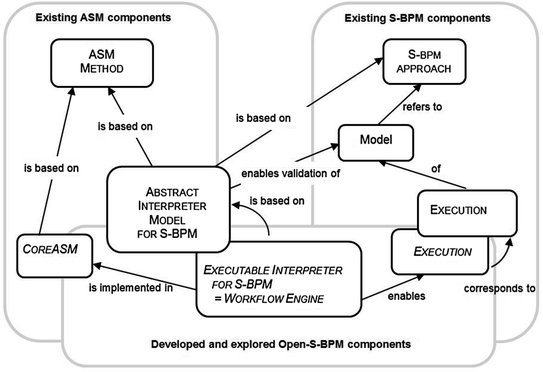
S-BPM and ASM components and their relations

On the one hand, a business process model based on the S-BPM approach can be processed automatically, as it covers a complete control flow specification for execution. This is the existing S-BPM part. On the other hand we have the existing ASM components. In the middle there is an existing Abstract Interpreter for S-BPM (Fleischmann 2012). In this case, “Abstract” has the meaning that the interpreter is on a high level and contains no detailed information for an actual implementation. Since this Abstract Interpreter is based on the S-BPM approach, it enables validation of an S-BPM model. The interpreter itself is based on the ASM method which offers a mathematical framework. This method has been developed for system engineering of complex, discrete, and dynamic systems like business process management systems. I will explain the basics of the theory behind ASM afterward. For now I will give you just an overview. The developments of the ASM method in the resent years have led to tools that allow for execution of ASM specifications. For several reasons I have chosen CoreASM as such a tool. I have used this tool to transfer the theoretical approach of the Abstract Interpreter in order to develop an executable interpreter. This interpreter allows not only the proof of the S-BPM concept, but also the automated execution of S-BPM models in terms of a workflow engine.
The concept of the Abstract State Machine was developed by Yuri Gurevich 30 years ago (Gurevich 1985). The Abstract State Machine is a scientifically well-founded system engineering method. It allows developing formal descriptions of algorithms, thus reducing unintended or erroneous system behavior. ASM is also a universal mathematical framework for semantic modeling of discrete dynamic systems. ASMs are based on mathematic algebras which consist of a nonempty set with a collection of operations defined over this set. Sets and relations are supported and therewith complex data structures like graphs can be built. Due to enhancements in the resent years, the ASM method has matured to an engineering method which can be utilized for the development of software and embedded hard-software systems (Börger and Stärk 2003). On the one hand, it is used for formal specification and on the other hand for analysis (verification and validation). With the semantically well-founded form of pseudo-code, system engineers are able to transform descriptions expressed in application domain terms into precise abstract definitions.
An ASM consists of a set of states and transition rules. Contrary to Finite State Machines (FSMs), a state is a structure in the sense of mathematical logics. Only one state is valid at a particular time. Starting from a defined initial state, a transition to a subsequent state occurs only under a certain condition. A transition from one state to a subsequent one is driven by transition rules.
Basic ASMs consist of a set of such transition rules of the following format (Börger and Stärk 2003):
If Condition then Updates
A condition (also called a guard) is a Boolean expression. Updates refer to a finite set of assignments which are performed in parallel in the course of the transition. An ASM computation step in a given state results in executing simultaneously all updates of all transition rules whose guard is true in the state if these updates are consistent, in which case the result of their execution yields the next state (Börger and Stärk 2003).
In addition to basic ASMs, which are executed as “single agent ASMs”, there exist enhancements to synchrony and asynchrony as well as “multi agent ASMs”. These enhancements include also additional transition rules which define the syntax of ASM programs. The “LET” rule is exemplarily for those powerful rules.
LET rule: let x = t in P
This rule allows for the assignment of the value t to x, followed by the execution of P. Variable x is a logical variable and cannot be updated by a transition rule. The scope of x is P. P is a transition rule and t may be a value or the result of a function.
Using ASMs, algorithms can be specified on the level of abstraction, as determined by the application domain. Hierarchical system design is supported by two concepts, namely ground model and refinement. Due to the abstraction and formalization with ASM, an efficient tool for requirements elicitation and precise modeling is available. Due to its versatility ASMs are used for analysis, design, and verification of complex, distributed, and discrete systems.
ASM as a method for software design and analysis has three constituents. Besides the concept of an abstract state machine, the ASM method has the two concepts ground model method, for capturing requirements, and the refinement method, for detailing ground models stepwise toward implementation (Börger and Stärk 2003).
A transformation of natural language into a formal precise description occurs in the course of requirements elicitation. Such a description as the result of the elicitation process is termed ground model (Börger and Stärk 2003). It serves the purpose of bringing the domain expert and system designer to a common understanding. The model can be verified and validated at the level of abstraction determined by the application domain (Börger 1999). “Ground models come with a sufficiently precise yet abstract and unambiguous meaning to carry out an implementation-independent, application-oriented requirements analysis (i.e., both verification and validation) prior to coding” (Börger and Stärk 2003).
The stepwise refining of higher abstraction ASMs leads to a lower abstraction level or even to executable code. This approach is well documented and can be readily inspected by mathematical means.
The “freedom of abstraction” (Börger 2003, p. 244) enables the designer to determine the vertical and horizontal refinement steps, in order to synchronize the different abstraction levels starting with customer expectations and ranging to final code. You are able to produce a high-level description of a system at a much earlier point in the design process, before all of the details have been decided.
The possibility of validating and verifying systems with ASM specifications has led to the development of ASM languages, enabling the execution of such specifications. In order to keep our implementation of the executable interpreter as close as possible to the abstract interpreter model for S-BPM, the instruction set of a corresponding tool needs to follow the mathematical definition of pure ASMs. In addition, as open source it facilitates exploration, adaptation, and enrichment. Finally, individual adaption of such a tool should be enabled, either to support users with a distinct user interface, or to integrate it with an existing framework.
Since CoreASM is an extensible ASM execution engine (Farahbod et al. 2007), it is utilized as a tool for the implementation of the executable interpreter. It is itself an interpreter.
-
Alessandro: I understood that S-BPM is an approach for BPM, and that ASM is a system engineering method, which sounds very theoretical. How can I imagine the relation to an S-BPM model.
-
Bernardo: Each BPM language has certain rules which describe the function of the specific language constructs and how to proceed with the modeled single process steps. Those rules are implemented in the Interpreter.
S-BPM is an approach for modeling business processes from a stakeholder’s perspective. It explicitly distinguishes between one’s individual work and the communication among the involved parties that is required to successfully accomplish a business goal.
Subject-oriented business process management (S-BPM) has been triggered by natural language constructs, namely standard sentences. They consist of subject, predicate and object (Fleischmann 2010). In the notation of S-BPM, subjects represent the active part of the process and can be a human or a system. Each subject has an internal behavior and communicates with other subjects. The latter requires the exchange of messages between subjects.
In order to accomplish a business goal a subject has to perform a set of interrelated activities in a certain sequence. S-BPM distinguishes between three fundamental types of activities for modeling the internal behavior. These types are sending messages to other subjects, receiving messages from other subjects, and executing internal actions like a program script if the subject is a system, or a manual task if the subject represents a person. Activities are denoted by predicates, and an object is the target of an activity. As in a natural language with subject-predicate-object (Fleischmann and Stary 2012), the object is the target of an activity and is not mandatory. Objects denoted as business objects can be manipulated in the course of the internal action or can be sent from one subject to another subject. But for further explanation I will focus only on subject and predicate.
-
Alessandro: I have a current situation from our assembly line in mind. For my understanding it would be very helpful to use an example with which I am familiar. I will give you a brief explanation of our production process. Please try to envision a product which is processed in sequence by several machine tools during a production process. The product communicates with a measurement machine and the transport system. First the product requests measurement. The measurement machine takes the product from the transport system and conducts the measurement. When the measurement machine has finished, it puts the product back on the transport system and sends a report with the result of the measurement to the product. The product knows about the tolerance range and compares this with the received report. In cases where the actual measurement is within the tolerance, the product informs the transport system to move forward to the next production step. Otherwise, the transport system receives a command to drop the product from the production sequence.
-
Bernardo: This is a good example which we can use for further explanations. For reasons of simplicity I suggest that we neglect other subjects like ERP systems or quality management systems.
Alessandro and Bernardo develop the interaction diagram and the behavior diagrams together. The following diagrams show the result (Figs. 13.2, 13.3, and 13.4).

Subject interaction diagram

Subject behavior diagram from subject measuring machine

Subject behavior diagram of the subject product
The behavior diagram of the subject Transport System is not depicted because it has no added value for further explanation.
-
Bernardo proceeds: For further explanation, I will focus on the behavior of the subject “Product,” which is detailed in the Subject Behavior Diagram we have modelled (Fig. 13.4). Such a diagram can be interpreted as directed graph. A graph consists of nodes connected by edges. A node has at least one ingoing and one outgoing edge. The basic structure of a node is depicted in Fig. 13.5.
Fig. 13.5 
Basic structure of a node

This concept must be extended (Fig. 13.6) because the behavior of a subject can be described using the three fundamental types of activities: send, receive, and action. Each node represents a state in terms of ASM. At each state the underlying subject performance of one of the three activities is assigned to the state. Only after you have finished an activity a subsequent activity can be started. One can understand an edge as a transition from one state to the next. A transition can only occur once the activity assigned to a node has been completed. In order to manage alternative transitions, each edge corresponds to an exit condition of the executed activity.

Extended structure of a node
-
Alessandro: With this information you are able to transfer the behavior diagram of a subject into a form which the interpreter can work with. Is that right?
-
Bernardo: That’s absolutely right. Let me draw the transformation for the subject “Product” (Fig. 13.7).
Fig. 13.7 
Transformation of the SBD from subject product into the graph structure

Mathematically speaking, a Subject Behavior Diagram (SBD) is a directed graph. Each SBD is assumed to be finite and to have one initial state and at least one end state. More than one end state is acceptable. Each path leads to at least one end state. At a definite time a subject can have only one single valid state. Unfortunately the ASM cannot interpret this figure of the graph so we have to use a proper notation. Therefore I will explain it for node “S2,” the most complex node in this example.
At first, we have to define general sets, which are a collection of possible values.
The set “State” contains all nodes of the SBD of the subject “Product.”
State = {S0, S1, S2, S3, S4, S5, S6}
The set “Services” contains all possible services or actions which can be performed.
Services = {send-S0, receive-S1, action-S2, send-S3, action-S4, send-S5, action-S6}
The set “Edges” contains all of the edges necessary for connecting the existing nodes in the given graph. An edge is denoted by the form fromNode_toNode. This means that the edge s0_s1 connects node S0 with node S1.
Edge = {s0_s1, s1_s2, s2_s3, s2_s5, s3_s4, s5_s6}
The possible exit conditions are enumerated in the set ExitCondition.
ExitConditions = {request_sent, report_received, drop_out, forward, drop_out_sent, forward_sent}
Each node has to know its incoming and outgoing edges. Therefore, we use the two sets “InEdge” and “OutEdge” to assign the ingoing and outgoing edges to each node, according to the given graph. We use predicates to depict this assignment. A predicate is a verb phrase template that describes a property of objects, or a relationship among objects represented by the variables. In our example the node S2 has one ingoing edge and two outgoing edges.
- InEdge(S2) := {s1_s2} :
-
read as: Node S2 has the ingoing edge s1_s2
- OutEdge(S2) := {s2_s3, s2_s5} :
-
read as: Node S2 has the outgoing edges s2_s3 and s2_s5
A service or activity is assigned to a node. A service can be one of the three fundamental types of activity (send, receive and action). ‘Service’ is not further specified for the function activity. In a function state, the assigned service could perform several tasks. For instance, a user interface (UI) or an external program could be invoked, or made to wait until a specific period of time has elapsed (like ripening in process industry). ‘Service’ needs to be specified with further refinements. For our purpose we have to define a predicate for the assignment of a service to a node. It works in the same way as for InEdge or OutEdge.
- Service(S2) := {action-S2} :
-
read as: action_s2 is the assigned service to node S2
Each edge needs to know its target node. Therefore, we use the predicate “target.”
- target(s2_s3) := {S3} :
-
read as: the target node from edge s2_s3 is node S3
It works the same way for all other nodes and edges.
-
Alessandro: Do I have to perform this transformation of the behavior diagram of a subject before I can use the interpreter?
-
Bernardo: No, you don’t have to transform the behavior diagram manually. Normally you will use a graphical editor to model the interaction diagram and the behavior diagrams of the subjects. The editor has to perform the transformation. The previous explanation was necessary for your understanding of the concept. The interpreter itself consists of a set of rules which are applied on such graphs. Based on these definitions for the graph, we can use the following ASM rule BEHAVIOR to show how to process the graph from the initial node to one of the end nodes. The rule BEHAVIOR is invoked with the underlying subject and a state. It uses the rules PROCEED, START, and PERFORM.
This ASM (Fig. 13.8) can be read in the following way: Each subject is in a given state at all times. This is termed SID_State, which is also a predicate. A transition from the current state to the next state within the Subject Behavior Diagram can only occur if the service (equal to the assigned activity) is completed. Therefore, the rule PERFORM will be executed until the predicate “Completed” confirms that the service has been completed. The edge to be taken to the successive state is selected by the function selectEdge.

ASM rule BEHAVIOR
When executing the transition to the successive state, the rule PROCEED sets the new current state of the subject (SID_State) and starts the service assigned to the successive state with the “START.” The rules PERFORM and START remain abstract at this time, as well as the functions Completed and selectEdge.
Due to the well-founded form of pseudo-code, the ASM rule BEHAVIOR is easy to read and understand. This rule for stepping through the graph is a fundamental rule of the interpreter. At this level an arbitrary behavior diagram in the form of a graph can be set up using the introduced structure of the nodes. This ASM can be stepwise refined.
Regarding our production example, the interpreter works as a workflow engine. Since there is no human involved the process runs automatically. If a human such as a quality employee would be involved in this process, the process would also run automatically. However, for activities which need human input the corresponding Subject Behavior Diagram awaits the input.
-
Alessandro: It is really manageable to follow the explanation on such an abstract level with the pseudo-code. How can I or others benefit from your work?
-
Bernardo: The result of this work will be accessible within the Open-S-BPM community. The Open-S-BPM project has been initiated to foster the spreading of the S-BPM concept and approach on a common theoretical and practical basis. It aims to establish a research platform for S-BPM developments. Within the S-BPM community, there are some projects focusing on the different activities of the S-BPM lifecycle (Fleischmann 2012). The development of the workflow engine is intertwined with some of these projects. The architecture is depicted in Fig. 13.9 (Schmidt and Fleischmann 2012).
Fig. 13.9 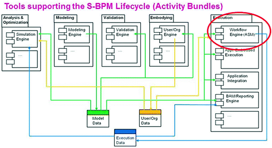
Architecture in Open-S-BPM

In BPM business processes pass several phases of deployment, ranging from analysis to design, modeling, validation, execution, monitoring, and optimization. This concept is commonly known as the BPM lifecycle. In Fig. 13.9 several components are depicted which are necessary to support such a lifecycle. Some of the components are implemented by current projects. The workflow engine is the main component which is necessary for execution. The Model Data is the basic input for the workflow engine. It contains the S-BPM process model which includes the interaction diagram and the behavior diagram of each subject. The storage format corresponds to the directed graph, which has been explained already in detail. The organizational structure of an organization is also relevant for execution. It is necessary to assign users to the subjects of the processes. Therefore, User/Org Data contains the required data. Those data are provided from an organization engine. When the workflow engine executes a process, many status data can be collected and held in a database. Those data can be used for monitoring or for the calculating of key performance indicators (KPI). All the information can be used to simulate changes in your processes. This mechanism allows you to evaluate the effects of the changes before you deploy the process.
The workflow engine serves as a baseline and as a reference implementation , ensuring semantic soundness for further language and processing developments of S-BPM. Here the strength and advantages of the ASM method can be utilized.
S-BPM and ASM are completely different methods from different fields. But, they have some similarities which make them worth dealing with.
You, Alessandro, can benefit from future developments in all of the areas of the S-BPM lifecycle. And you can contribute to these developments through active participation within the S-BPM community. Particularly, practitioners are welcome to bring their perspective.
3 Closing
In the meanwhile, the last presentation of the day on this conference has finished, and the participants are on their way to a common evening event. Alessandro and Bernardo join the other participants and are going to have some other fruitful and interesting discussions.
References
Börger E (1999) High level system design and analysis using abstract state machines. In: Hutter D, Stephan W, Traverso P, Ullmann M (eds) Applied formal methods—FM-trends 98, LNCS, vol 1641. Springer, Berlin, pp 1–43
Börger E (2003) The ASM refinement method. Formal Aspects Comput 15(2–3):237–257. doi:10.1007/s00165-003-0012-7
Börger E, Stärk R (2003) Abstract state machines. A method for high-level system design and analysis (19 tables). Springer, Berlin
Farahbod R, Gervasi V, Glässer U (2007) CoreASM: an extensible ASM execution engine. Fundamenta Informaticae 77(1):71–103
Fleischmann A (2010) What is S-BPM? In: Buchwald H, Fleischmann A, Seese D, Stary C (eds) S-BPM ONE—setting the stage for subject-oriented business process management, LNBIP, vol 85. Springer, Berlin, pp 85–106
Fleischmann A (2012) Subject-oriented business process management. Springer, Heidelberg
Fleischmann A, Stary C (2012) Whom to talk to? A stakeholder perspective on business process development. Univ Access Inf Soc 11(2):125–150. doi:10.1007/s10209-011-0236-x
Gurevich Y (1985) A new thesis. In: Abstracts, American Mathematical Society, vol 6, p 317
Lerchner H, Stary C (2014) An open S-BPM runtime environment based on abstract state machines. In: IEEE 16th conference on business informatics (CBI), pp 54–61
Schmidt W, Fleischmann A (2012) Open-S-BPM white paper. Goals and Architecture. http://www.i2pm.net/open-s-bpm
Author information
Authors and Affiliations
Corresponding author
Editor information
Editors and Affiliations
Rights and permissions
Open Access This chapter is distributed under the terms of the Creative Commons Attribution Noncommercial License, which permits any noncommercial use, distribution, and reproduction in any medium, provided the original author(s) and source are credited.
Copyright information
© 2015 The Author(s)
About this chapter
Cite this chapter
Lerchner, H. (2015). An Abstract State Machine Interpreter for S-BPM. In: Fleischmann, A., Schmidt, W., Stary, C. (eds) S-BPM in the Wild. Springer, Cham. https://doi.org/10.1007/978-3-319-17542-3_13
Download citation
DOI: https://doi.org/10.1007/978-3-319-17542-3_13
Published:
Publisher Name: Springer, Cham
Print ISBN: 978-3-319-17541-6
Online ISBN: 978-3-319-17542-3
eBook Packages: Computer ScienceComputer Science (R0)