
Abstract
We present a formal framework to certify k-induction-based model checking results. The key idea is the notion of a k-witness circuit which simulates the given circuit and has a simple inductive invariant serving as proof certificate. Our approach allows to check proofs with an independent proof checker by reducing the certification problem to pure SAT checks and checking a simple QBF with one quantifier alternation. We also present Certifaiger, the resulting certification toolkit, and evaluate it on instances from the hardware model checking competition. Our experiments show the practical use of our certification method.
You have full access to this open access chapter, Download conference paper PDF
1 Introduction
In many verification applications, k-induction [34] (also known as temporal induction) is used as a powerful technique that reduces model checking to a series of SAT problems. It has been extensively investigated as an effective approach for unbounded model checking [18, 22]. As a generalisation of simple induction, for a given safety property, the k-induction method concerns a base case and an inductive case: the base case is a bounded model checking problem with a depth of k; the inductive case assumes the property holds for k consecutive steps, then checks it also holds for \(k\,+\,1\) steps. The safety property is said to be k-inductive if both conditions are satisfied. The nature of the k-induction algorithm allows it to be integrated with modern SAT/SMT solvers. For example, reduction techniques such as preprocessing have been investigated with k-induction in an incremental setting [17]. The present state-of-the-art also concerns combining k-induction with existing SAT-based model checking (SMC) techniques including interpolation and property directed reachability [23, 27]. Furthermore, k-induction has also been extended to the context of infinite-state systems [13, 19, 26, 32], as well as software verification [16]. Another variant of this line of research is the use of k-induction in sequential equivalence checking [31].
Model checking has been an effective technique for the verification of safety-critical systems. In particular, applications deployed in industrial settings such as nuclear facilities, increasingly utilise model checking to gain trust in the correctness of their designs [20, 30, 36]. In such ultra safety-critical applications the certification that the model checking results are in fact correct is crucial. We argue that in model checking generic machine checkable certification is still in its infancy in contrast to related fields. For instance in SAT competitions [2, 24], certifiable proofs are mandatory. This has helped to improve the trust we have in SAT solving results as well as the quality of SAT solvers tremendously.
Even though counterexample validation is commonly used in model checking to certify negative verification results through simulation, producing a generic machine checkable proof on success is less straight-forward. To mitigate this problem, certification of model checking has been suggested earlier in [14, 21, 23, 29, 33, 36, 37], but the methods presented in these works are either not directly applicable to k-induction (in its vanilla form), produce k-induction specific certificates (fail to provide an inductive invariant), or are considered to have exponential certificates. This apparently made it hard to, e.g., require all model checkers to produce proofs in the hardware model checking competitions.
As symbolic model checking of bit-level properties for hardware circuits is PSPACE-complete, we introduce in this paper a novel certification framework for k-induction-based model checking. Our proposed approach generates a fixed number of SAT problems together with a one-alternation only QBF, which are verified by an independent certifier, thereby enabling the certification of k-induction proofs at lower complexity. Our method efficiently extends the given model checking problem to finding a simple inductive invariant of a larger circuit as a proof of k-induction of the original circuit. In particular, the certificate size (as a circuit) is shown to be linear in size of the given model, and the inductive depth. We present Certifaiger, which works as a complete tool suite for certification, independent of any model checker. Experimental results show that our technique works efficiently and can be adapted for practical use.
The rest of the paper is organised as follows: In Sect. 2 we introduce the notion of combinational simulation in the context of circuits. In Sect. 3, we study the formal property of combinational simulation and define k-induction-based model checking with an example. In Sect. 4, we present our proposed certification approach followed by theoretical results in terms of k-induction. We describe the implementation of our tool suite in Sect. 5, and report on experimental results in Sect. 6. Finally, we conclude in Sect. 7.
2 Circuits
In this section, we present a slightly non-standard notation to formalize systems. It allows us to represent systems and particularly circuits symbolically in a compact way and is crucial to reduce notational clutter in the following.
Let \(\mathbb {B}(V)\) be the set of Boolean expressions (propositional formulas) over the Boolean variables V. We also write \(\mathbb {B}(I,L)\) to denote the set of Boolean expressions over \(I \cup L\), where I and L are two sets of Boolean variables. Given two Boolean expressions f(V), \(g(V) \in \mathbb {B}(V)\) we call them equivalent, written \(f(V) \equiv g(V)\), if they have the same models. This notation is also applied to Boolean expressions over different sets of variables by simply interpreting them over the union of their variables. We use “\(\simeq \)” for syntactic equivalence [15], “\(\rightarrow \)” for syntactic implication, and “\(\Rightarrow \)” for semantic implication. To define semantical concepts or abbreviations we stick to equality “\(=\)”.
In the context of this paper, models are expressed in the form of finite logical circuits, where states can be seen as truth assignments to latches and inputs. Initial states are defined by the reset values of latches, in our case, represented by their reset functions. For each latch l in L, there is a reset function \(r_l(L)\) which is a formula (Boolean expression) over a set of latches L, thus allowing cyclic definitions. Note that a cyclic definition can lead to unsatisfiable reset formulas, in which case there are simply no initial states. Additionally, for some \(L''\subseteq L\), we define \(R(L'') = \bigwedge \limits _{l\in L''} l\simeq r_l(L)\) to allow us to analyse reset functions of individual subsets of latches. The transition relation is expressed as a “next state” formula associated with each latch, whereas non-determinism comes from inputs (which act as the environment). The successor value of each latch is defined by applying its transition function on the current values of latches and inputs. Intuitively, a safety property specifies that the system must not violate certain behaviours, i.e., only “good states” are reachable. In this paper we focus on such simple safety properties and leave liveness properties (see e.g., [29]) etc. for future work.
Definition 1
(Circuit). A circuit \(C=(I, L, R, F, P)\) is defined as follows:
-
1.
I: the set of Boolean input variables.
-
2.
L: the set of Boolean latch variables.
-
3.
\(R= \{ r_l(L) \mid l \in L\}\) is a set of reset function formulas.
-
4.
\(F=\{ f_l(I,L) \mid l \in L\}\) is a set of transition function formulas, such that for every latch \(l\in L\), there is a transition function formula \(f_l(I, L) \in \mathbb {B}(I,L)\).
-
5.
\(P(I,L) \in \mathbb {B}(I, L)\) is a formula encoding the (good states) property.
The reset functions characterise the initialisation of the circuit. Such definition of reset abstracts the way how circuits are reset. As a short-hand we use \(L'\simeq F(I,L)\) to denote a conjunction of the corresponding equivalences, i.e., it is interpreted as \(\bigwedge \limits _{l\in L'} l'\simeq f_{l}(I,L)\). For clarity, we use subscripts as in \(L_i\) to denote a copy of the latch variables L in the temporal direction at some timestamp i, where \(L_0\) is the set of latches at timestamp 0 when the circuit is supposed to be initialised. Note that, using such transition functions to describe transition relations implies that there will always be a successor state. The temporal evolution of a system is expressed using the notion of unrolling, which has a specific length and follows the transition relation at each step.
Definition 2
(Unrolling). For an unrolling depth \(m\in \mathbb {N}\), the unrolling of a circuit C of length m is defined as the formula \(U_m= \bigwedge \limits _{i\in [0,m)} (L_{i+1}\simeq F(I_i, L_i)) \).
Note that in this definition, we use \(I_i\) and \(L_i\) as sets of variables, whereas \(U_m\) is a formula. For \(m=0\), the conjunction is empty thus the formula is trivial.
Definition 3
(Initialised unrolling). An initialised unrolling of a circuit C, with \(C=(I, L, R, F, P)\), is defined as \(U_m\wedge R(L_0)\), where \(U_m\) is an unrolling.
We say an unrolling is safe if and only if the property holds at every timestamp along the whole length of the unrolling.
Definition 4
(Safe unrolling). Unrolling \(U_m\) of a circuit \(C=(I, L, R, F, P)\) is said to be safe if
Definition 5
(Safe initialised unrolling). An initialised unrolling \(U_m\wedge R(L_0)\) of a circuit \(C=(I, L, R, F, P)\) is said to be safe if
We are now ready to introduce the notion of a combinational extension between two circuits. It is purely syntactic based on sharing inputs and latches.
Definition 6
(Combinational extension). Given circuits \(C=(I, L, R, F, P)\) and \(C'=(I', L', R', F', P')\), \(C'\) combinationally extends C if \(I = I'\) and \(L \subseteq L'\).
As noticed above, this definition allows us to interpret the inputs and latches of a circuit as being part of another circuit. In practice for instance we simply assume that the first |L| latches of the circuit \(C'\) are mapped to those of C assuming some ordering of the latches, as it is for instance the case in the AIGER format [7] used in the Hardware Model Checking Competition (HWMCC) [5].
To tackle the problem of generating a proof certificate for k-induction of the safety of a circuit C, as is the main goal of this paper, we extend it to a larger circuit \(C'\) with additional “book-keeping” behaviours [1] for which we can show the same property by using standard induction. To ensure that the resulting extended circuit \(C'\) preserves the original property, we provide a formalization through a combinational simulation relation between two circuits, which needs to be formally verified by a certifier. One important aspect of our design principles is to keep the complexity of the required certification procedure low, in other words, to be done via pure SAT solver checks or by solving a QBF with at most one quantifier alternation. This leads to a more complicated non-standard design of the certification approach, the details of which will be described in Sect. 4.
From a practical perspective, under combinational simulation defined below in Definition 7, we require that the transition functions on the “common” parts of the two circuits are equivalent. For the new latches, the transition functions are always satisfiable (as they are functions), and thus we need no constraints on them. As second condition we require that if the safety property \(P'\) holds in the extended circuit, then the property P holds in the original circuit. The last condition we need to check is that all the new latches of the extended circuit can be initialised with some values whenever the original circuit can be initialised and using the same values for initialising the common latches. In other words, for all initialisations of the original circuit there is at least one initialisation of the extended circuit with the same values for common latches.
Under these conditions Theorem 1 in Sect. 3 shows that if the extended circuit (in this sense) combinationally simulates the original one and the extended circuit is safe then the original circuit is safe as well.
With some abuse of notation, we use \(\exists L\) in a Quantified Boolean Formula (QBF) to denote existential quantification over variables in L. As usual, free variables are (implicitly) assumed to be quantified universally.
Definition 7
(Combinational simulation). Given circuits \(C=(I, L, R, F, P)\) and \(C'=(I', L', R', F', P')\) where \(C'\) combinationally extends C, we say that \(C'\) combinationally simulates C, if the following holds:
-
1.
\(f_l(I, L)\equiv f'_l(I,L')\) for \(l\in L\), “transition”
-
2.
\(P'(I,L')\Rightarrow P(I,L)\), and “property”
-
3.
\(R(L) \Rightarrow \exists (L'\backslash L) R'(L')\). “reset”
In later context when verifying the combinational simulation relation between two circuits, we refer to Definition 7.1 as the transition check, Definition 7.2 as the property check, and Definition 7.3 as the reset check.
3 Model Checking
In this section, we consider model checking via k-induction. The model checking problem for safety properties concerns determining whether, given a circuit with a property P, it is the case that P holds in all reachable states, i.e., the initialised unrolling of a circuit of any arbitrary length is safe.
Definition 8
(Safe circuit). Let \(U_m\) be the unrolling of circuit C, C is safe iff \(U_m \wedge R(L_0) \Rightarrow \bigwedge \limits _{i\in [0,m]} P(I_i, L_i)\) holds for all \(m\in \mathbb {N}\).
Based on the above definition, we say the property P “holds” in C if the circuit is safe with respect to P.
Theorem 1
Assume that the circuit \(C'\) combinationally simulates the circuit C. If \(C'\) is safe, then C is safe.
Proof
We do a proof by contradiction. Let \(m\in \mathbb {N}\) be a bound for which the claim does not hold. Thus the unrolling of length m of \(C'\) is safe w.r.t. P, and therefore \(U'_m\wedge R'(L'_0)\Rightarrow \bigwedge \limits _{i\in [0,m]}P'(I'_i,L'_i)\) holds. To obtain the contradiction we assume there is a satisfying assignment s of \(U_m\wedge R(L_0)\wedge \lnot \bigwedge \limits _{i\in [0,m]} P(I_i,L_i)\), which would make C not to be safe. Thus \(R(L_0)\) needs to be satisfiable. Now the reset check of Definition 7.3 implies that \(R'(L'_0)\wedge R(L_0)\) is guaranteed to be satisfiable with \(L_0\) being a subset of \(L'_0\). Moreover, by Definition 7.1, the unrolling \(U'_m\) of \(C'\) is also satisfiable with the transition function F applied on the projected (“common”) component on both circuits. Also for the new latches the fact that we use a transition function for them, they are also satisfiable (transition functions guarantee that there is always a successor state for all states). Therefore the initialised unrolling \(R'(L'_0)\,\wedge \,U'_m\) is satisfiable. Furthermore, by our assumption, \(\bigwedge \limits _{i\in [0,m]}P'(I'_i,L'_i)\) holds. By Definition 7.1 and Definition 7.3, the projected latches of \(C'\) stay the same as \(L_i\) for all \(i\in [0,m]\), and thus by Definition 7.2 we have that \(\bigwedge \limits _{i\in [0,m]}P(I_i,L_i)\) holds. \(\square \)
As usual, we call a formula \(\phi \) to be an inductive invariant \(\phi \) of a circuit C if \(\phi \) satisfies the following conditions: (1) \(R(L)\Rightarrow \phi (I,L)\), (2) \(\phi (I,L)\Rightarrow P(I,L)\), and (3) \(U_1\wedge \phi (I_0,L_0)\Rightarrow \phi (I_{1}, L_{1})\). As a generalisation, k-induction looks at k steps of evolution rather than 1 step by assuming the property holds in k consecutive timestamps at the induction step.
Definition 9
(k-inductive). Given a circuit C with a property P, define the formula \(S_k = \bigwedge \limits _{i\in [0,k)}P(I_i, L_i)\). Then P is called k-inductive in C if and only if the following two conditions hold:
-
1.
\( U_{k-1} \wedge R(L_0) \Rightarrow S_k\), and “initiation”
-
2.
\(U_k\wedge S_k\Rightarrow P(I_k, L_k)\). “consecution”
The first condition Definition 9.1 in this definition is called initiation check, also bounded model checking check or simply BMC check on the initialised unrolling of length \(k-1\), whereas the second condition Definition 9.2 is referred to as the consecution check for the unrolling of k. Note that a 1-inductive invariant is equivalent to an inductive invariant when \(\phi (I,L)\equiv P(I,L)\).

The SMV code for the Counter example.

The transition diagram of the Counter example. The initial state is “000” (colored yellow). In the (gray) “bad” State “110” the property does not hold. (Color figure online)
Example 1
We consider a simple example of an N-bit counter, where the counter counts up to a modulo bound m, then it resets to zero. There is also a reset signal which works as an enabler, such that when the signal is set to 1, the counter is forced to reset. The property checks whether the counter value reaches b. Here the exact modulo check makes the model checking problem k-inductive (\(k = b - m + 1\)). More precisely, for \(N=3\), the formal description of a 3-bit counter is given in the SMV language in Fig. 1, where \(m=5, b=6\). (Note that our example can be easily extended to integers too.) The state diagram of this system is shown in Fig. 2. The input values are specified with the transition relations. This model is 2-inductive.
4 Certification
In our suggested approach, certifying model checking results concerns finding and checking an inductive invariant which implies the original specification, which in our case, is the safety property P. To tackle the problem of certifying k-induction-based model checking for any given circuit, in this section, we redirect the problem to generating a simple inductive invariant from a k-witness circuit, in which the original circuit is combinationally simulated.
We start by defining the formalism of a k-witness circuit. The main idea is to record the previous \(k-1\) states and inputs of the circuit observed during the execution, “flattening” the k-induction procedure back to normal induction of a larger circuit. As a result, the size of the circuit increases by a factor of k, where k is the constant used in the k-induction scheme. The k-witness circuit has k local components of inputs and latches. Each component can be seen as representing a state in the original circuit. Whenever a new state is saved, the oldest one is discarded.
One of the key technical challenges is the proper initialisation of the k-witness circuit. We use an additional k initialisation bits for indicating which components of the circuit have been initialised. This helps accomplishing the combinational simulation relation later. We say a component is initialised if its initialisation bit is \(\top \). At initialisation, the k-witness circuit can be either fully or partially initialised. Figure 3 displays three ways of initialising the components. In the case of full initialisation, the circuit pre-computes k steps of the original circuit as the initial state of the k-witness circuit. Thus intuitively in the full initialisation case the initial state of the k-witness circuit encodes the states reachable in the k-step initialised BMC unrolling of the original circuit. In partial initialisation scenarios the circuit instead pre-computes an initialised BMC unrolling for fewer steps, where some components are left uninitialised. In the final case where there are no pre-computed steps, the circuit simply runs from an original initial state, leaving all the other components fully uninitialised.
In the definitions below, we use the superscript of i in \(L^i\) to denote a copy of latches L in the spacial direction, such that we introduce a set of new latch variables for every \(L^i\), where \(l^i \in L^i\) is the corresponding copy of \(l \in L\), and similarly for inputs. We refer to \(l^i\) as some latch in \(L^i\), where i is the index of a latch set \(L^i\). The formal definition of k-witness circuit is given below. We continue to use subscripts for the temporal direction.
Definition 10
(k-witness circuit). Given a circuit \(C=(I, L, R, F, P)\), and \(k\in \mathbb {N}^+\), the k-witness circuit
 of C is defined as follows:
-
1.
 . For simplicity we also refer to \(I'\) as \(X^{k-1}\).
 -
2.
 , such that,
 -
(a)
\(X^i\) is a copy of the original inputs, for all \(i\in [0,k-2]\).
-
(b)
\(L^i\) is a copy of the original latches, for all \(i\in [0,k-1]\).
-
(c)
\(B=\{b^0,\dots ,b^{k-1}\}\) is the set of initialisation bits.
-
(a)
-
3.
The reset function
 is defined as follows:
 -
(a)
For \(x\in X^0\cup \dots \cup X^{k-2}, r'_{x} = x\).
-
(b)
For \(i\in [1,k-1)\), \(u^i=R(L^i)\vee u^{i+1},\) and \(u^{k-1} = R(L^{k-1})\).
-
(c)
For \(l \in L^0\), \(r'_{l} = \mathsf {ite}(u^1, l, r_l(L^0))\).
-
(d)
For \(i \in [1, k)\), \(r'_{l^i} = \mathsf {ite}(u^i, l^i, f_{l^i}(X^{i-1}, L^{i-1}))\).
-
(e)
\(r'_{b^{k-1}} = \top \).
-
(f)
\(r'_{b^0} =\lnot u^1\).
-
(g)
For \(i\in [1,k-1)\), \(r'_{b^i}= b^{i-1} \vee (R(L^i) \wedge \lnot u^{i+1})\).
-
(a)
-
4.
 is defined as follows:
 -
(a)
For \(i\in [0,k-1)\), \(f'_{x^{i}}(I',L')=x^{i+1}\).
-
(b)
For \(l\in L^{k-1}\), \(f'_{l}(I',L') = f_{l}(X^{k-1},L^{k-1})\).
-
(c)
For \(i \in [0,k-1)\), \(f'_{l^{i}}(I',L')= l^{i+1}\).
-
(d)
For \(i\in [0,k-1)\), \(f'_{b^i}(I',L') = b^{i+1}\), and \(f'_{b^{k-1}}(I',L') = b^{k-1} \).
-
(a)
-
5.
The property
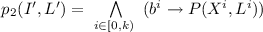
 is defined as \(P'(I',L') = \bigwedge \limits _{i\in [0,4]} p_i(I',L')\) such that:
 -
(a)
For \(i\in [0,k-1)\), \(h^i = (L^{i+1} \simeq F(X^{i}, L^{i}))\).
-
(b)
 .
. -
(c)
 .
. -
(d)
 .
. -
(e)
 .
. -
(f)

-
(a)
 . For simplicity we also refer to
  , such that,
  is defined as follows:
  is defined as follows:
  is defined as
  .
. .
. .
. .
.
In Definition 10 we list five parts of the k-witness circuit. For clarity, we explain each part in more details in the following text:
-
1.
The set of inputs is identical to that of the original circuit.
-
2.
The set of latches consists of the original latches, k initialisation bits, and an additional \(k-1\) copies of inputs and latches which are introduced to save observations of previous states.
-
3.
The reset function is defined to allow non-deterministic initialisation (see Fig. 3), where we use helper variables \(u^i\) for a more compact encoding. The formula \(u^i\) is satisfied whenever a component younger than the ith has the same reset value as the original circuit. The reset functions of the \(X^i\) latches (for \(i < k-1\)) ensure they are initialised in a non-deterministic fashion. As for the initialisation bits B, their reset values are deterministic, depending on the initialisation status of the components.
-
4.
The transition function of the \((k-1)\)th copy of latches is identical to the original transition function, while every older component simply saves the value of its one timestep younger component.
-
5.
Finally, the property is composed of five sub-properties, where \(h^i\) is satisfied whenever the two adjacent components follow the original transition relation.
Figure 4 illustrates a comparison of variable structures of the original circuit and its k-witness (this also suggests their combinational extension relation). The area marked yellow (left box and top right box on the right) consists of the same set of variables. We consider each pair \((X^i,L^i)\) as a component in the circuit and refer to \((X^{k-1}, L^{k-1})\) as the most recent component (youngest copy), and \((X^0,L^0)\) as the oldest component (copy). Additionally we also refer to the inputs \(I'\) as \(X^{k-1}\) for convenience.

The diagram shows three possible initial states of \(C'\). Here (1) illustrates 1-initialisation, (2) is i-initialisation, and (3) full initialisation. The grey area are the uninitialised components (the “don’t care”s).

The structure of input and latch variables in C and \(C'\). (Color figure online)
The property \(P'\) is comprised of five sub-properties. The monotonicity property \(p_0\) expresses the monotonic nature of the initialisation bits. Intuitively, if a component is initialised, all components younger than it should also be initialised. The transition property \(p_1\) expresses the property that every initialised component has to follow the transition relation in the original circuit. Of particular interest is the k-safety property \(p_2\), which says the original property P needs to be satisfied in every initialised component. The reset property \(p_3\) expresses the property that in the case of partial initialisation, the oldest initialised component needs to satisfy the original reset function. Finally, \(p_4\) expresses that at least the youngest component should have the initialisation bit set.
We now show the combinational simulation relation between the original circuit and its k-witness circuit.
Theorem 2
The circuit C is combinationally simulated by its k-witness circuit.
Proof
By the construction in Definition 10, the inputs stay the same in the k-witness circuit \(C'\), and the new latches are a superset of the original ones (the youngest component in \(C'\)). Thus by Definition 6, \(C'\) combinationally extends C. Based on Definition 10.4, the transition function of \(L^{k-1}\) is identical to the original one, which satisfies Definition 7.1. In the new property, \(p_4\) and \(p_2\) together imply \(P(X^{k-1}, L^{k-1})\). In other words, the original property holds in the most recent component. This then satisfies Definition 7.2. By Definition 10, for every satisfiable assignment of R(L), the same assignment satisfies \(R'(L)\) on the common latches (the youngest component). For all the new latches we observe the following. Because the reset of the newest component is satisfiable with the same assignment as in the original circuit, we can see that \(u^{k-1}\) is true in the k-witness circuit and therefore all other \(u^{i}\) are also true. Therefore all the \(\mathsf {ite}\)-statements of the reset definition become trivially satisfiable. To complete the argument, by Definition 10.3, all the initialisation bits can be now set to \(\bot \) except \(b^{k-1}\) which can be set to \(\top \). A satisfying assignment of \(R'(L')\) can thus be directly constructed (deterministically in polynomial time) from any satisfying assignment of R(L). This implies the reset condition of Definition 7.3 holds. (Sidenote: This implies that the QBF check needed in the combinational simulation relation could potentially be solved easily in practice for these k-witness circuits.) Therefore \(C'\) combinationally simulates C. \(\square \)
In the following, we present the main result of this paper on the relationship between a circuit C and its k-witness circuit \(C'\) in terms of k-induction.
Theorem 3
Given a circuit C, a fixed \(k\in \mathbb {N}^+\), and its k-witness circuit \(C'\), P is k-inductive in C iff \(P'\) is 1-inductive in \(C'\).
Proof
We consider the two k-inductive checks in Definition 9 for both directions. In Theorem 4 we show that the BMC check (of the initialised unrolling of length \(k-1\)) in C passes, if and only if the same check (of the initialised unrolling of length 0) in \(C'\) also passes. In Theorem 5 we prove that if the consecution check of \(C'\) passes, then the consecution check also passes in C. Lastly, Theorem 6 shows that if P is k-inductive in C, then the consecution check of \(P'\) using the unrolling of length 1 passes in \(C'\). By combining them together, we conclude P is k-inductive in C iff \(P'\) is 1-inductive in \(C'\). \(\square \)
For the BMC check in the two circuits, we need to analyse three separate cases as shown in Fig. 3, which correspond to Lemmas 2, 3, and 4, respectively. But before this we need a technical Lemma 1 on the initialisation bits. In the following context, we consider a given circuit C, and its k-witness circuit \(C'\) with a fixed k.
Lemma 1
For the initialised unrolling of length 0 of the k-witness circuit \(C'\), the reset values of the initialisation bits \(B_0\) are deterministic and depend only on the component with the largest index \(i\in [0,k)\) for which \(R(L^i_0)\) is satisfied.
Proof
Firstly, we define \(S=\{i\mid R(L^i_0)\}\), based on which we consider two cases.
(1). By Definition 10.3(c), if \(\lnot u^1_0\), then \(0\in S\). In this case, \(b^0_0= \top \) by Definition 10.3(f), and by Definition 10.3(e)(g), \(b^1_0,...,b^{k-1}_0\) are all set to \(\top \).
(2). Otherwise we consider \(u^1_0\), where S contains at least some \(i\in [1,k)\). Let m be the maximum index in S, and \(m\ne 0\). Since \(R(L^m_0)\), \(u^m_0\) is satisfied, so are \(u^{m-1}_0,...,u^1_0\), while \(u^{m+1}_0,...,u^{k-1}_0\) are not. In Definition 10.3(g), for all \(i\in S\), \(R(L^i_0)\wedge \lnot u^{i+1} \) is only satisfied when \(i=m\), thus \(b^m_0= \top \). Therefore \(b^i_0=\top \) for all \(i\in [m+1, k)\). By Definition 10.3(f), \(b^0_0=\bot \), therefore for all \(i\in [1,m), b^i_0=\bot \). \(\square \)
Initialisation bits are indicators for the initialisation status of the k-witness circuit. We observe that the sub-properties \(p_0,...,p_3\) of the k-witness circuit trivially hold for uninitialised components (i.e., those for which the initialisation bit is 0), while \(p_4\) solely depends on \(b^{k-1}\).
Lemma 2
If the initialised unrolling of length \(k-1\) of the original circuit C is safe, the initialised unrolling of length 0 of the k-witness circuit \(C'\) is also safe, in the case of 1-initialisation.
Proof
Assume \(U_{k-1}\wedge R(L_0)\Rightarrow \bigwedge \limits _{i\in [0,k)}P(I_i,L_i)\) such that the initialised unrolling of C is safe. In the case of 1-initialisation, we consider \(R'(L'_0)\wedge R(L^{k-1}_0)\) as the initialised unrolling of \(C'\), as \(U'_0\) is trivial. By Lemma 1 and Definition 10.3, for the initialisation bits, only \(b^{k-1}_0\) is set to \(\top \) and the rest remain \(\bot \). The values of \(B_0\) then satisfy \(p_0(I'_0, L'_0), p_1(I'_0, L'_0),p_4(I'_0, L'_0)\) trivially. Every satisfying assignment of \(R'(L'_0)\wedge R(L^{k-1}_0)\) satisfies \(R(L_0)\) with \(L_0= L^{k-1}_0, I_0= X^{k-1}_0\). Similar to our argument in Theorem 1, \(U_{k-1}\wedge R(L_0)\) is then also satisfiable. By our assumption, \(P(X^{k-1}_0,L^{k-1}_0)\) is thus satisfied. The premise of \(p_2(I'_0,L'_0)\) is only satisfied for \(b^{k-1}_0\), and with the same assignment satisfying \(P(X^{k-1}_0,L^{k-1}_0)\), \(p_2(I'_0,L'_0)\) is also satisfied. Lastly, the premise of \(p_3(I'_0,L'_0)\) is only satisfied for \(\lnot b^{k-2}_0\wedge b^{k-1}_0\), and since \(R(L^{k-1}_0), p_3(I'_0,L'_0)\) is satisfied. Therefore we have \(P'(I'_0,L'_0)\). \(\square \)
Lemma 3
If the initialised unrolling of length \(k-1\) of the original circuit C is safe, the initialised unrolling of length 0 of the k-witness circuit \(C'\) is also safe, in the case of i-initialisation.
Proof
Firstly, we assume \(U_{k-1}\wedge R(L)\Rightarrow \bigwedge \limits _{i\in [0,k)}P(I_i,L_i)\). In the case of i-initialisation, we consider \(R'(L'_0)\wedge R(L^m_0)\wedge \lnot u^{m-1}\) as the initialised unrolling of \(C'\), where \(m\in [1,k-1)\) is the largest index for which \(R(L^m_0)\) is satisfied. As we showed in Lemma 1, \(b^m_0,...,b^{k-1}_0\) are set to \(\top \) while \(b^0_0,...b^{m-1}_0\) are \(\bot \). Following Definition 10.3, \(L^i_0\simeq F(X^{i-1}_0,L^{i-1}_0)\) for all \(i\in (m,k)\), while all components older than m are uninitialised. Every satisfying assignment of \(R'(L'_0)\,\wedge \,R(L^m_0)\,\wedge \, \lnot u^{m-1}\) also satisfies \(\bigwedge \limits _{i\in [0,k-m-1)}(L_{i+1}\simeq F(I_i,L_i))\wedge R(L_0)\) with \(I_{i-m}=X^i_0, L_{i-m}=L^i_0\) for all \(i\in [m,k)\). In the rest of the proof, we fix the assignment satisfying \(R'(L'_0)\wedge R(L^m_0)\,\wedge \, \lnot u^{m-1}\). Similar to our argument in Theorem 1, \(U_{k-1}\,\wedge \,R(L_0)\) is satisfiable with our fixed assignment. By our assumption, \(\bigwedge \limits _{i\in [m,k)}P(X^i_0,L^i_0)\) is then satisfied. We now consider \(P'(I'_0, L'_0)\). As the premise of \(p_2(I'_0, L'_0)\) is only satisfied for \(b^m_0,...,b^{k-1}_0\), \(p_2(I'_0, L'_0)\) is satisfied. Similarly for the transition property, with \(L^i_0\simeq F(X^{i-1}_0,L^{i-1}_0)\) for all \(i\in (m,k)\), \(p_1(I'_0,L'_0)\) is satisfied. Given the values of \(B_0\), the monotonicity property is satisfied. In addition, \(p_4(I'_0,L'_0)\) is also satisfied as \(b^{k-1}_0=\top \). Finally, the premise of \(p_3(I'_0,L'_0)\) is only satisfied for \(\lnot b^{m-1}_0\wedge b^m_0\), and as we already have \(R(L^m_0)\), \(p_3\) is satisfied. \(\square \)
Lemma 4
If the initialised unrolling of length \(k-1\) of the original circuit C is safe, the initialised unrolling of length 0 of the k-witness circuit \(C'\) is also safe, in the case of full initialisation.
Proof
We assume \(U_{k-1}\wedge R(L)\Rightarrow \bigwedge \limits _{i\in [0,k)}P(I_i,L_i)\) for the original circuit. Since we consider full initialisation, \(R'(L'_0)\wedge R(L_0^0)\wedge \lnot u^1_0\) is the initialised unrolling of \(C'\). Following Definition 10.3, \(L^i_0\simeq F(X^{i-1}_0,L^{i-1}_0)\) for all \(i\in [1,k)\). Every satisfying assignment of \(R'(L'_0)\,\wedge \,R(L_0^0)\,\wedge \, \lnot u^1_0\) satisfies \(U_{k-1}\,\wedge \, R(L_0)\) with \(I_{i}=X^i_0, L_{i}=L^i_0\) for all \(i\in [0,k)\). The rest of the proof follows the same logic as in Lemma 3. \(\square \)
Lemma 5
If the BMC check for the unrolling of length \(k-1\) of the original circuit C passes, then the BMC check for the unrolling of length 0 of the k-witness circuit \(C'\) also passes.
Proof
Based on Definition 10.3, we consider the BMC check for all possible initial states. Lemma 2, 3 and 4 cover the case-split over all initial states of \(C'\) based on whether each component satisfies the original reset function \(R(L^i_0)\) or not. We show that the BMC check of \(C'\) passes under the same assumption for three initialisation cases respectively. In particular, our construction in Definition 10.3 does not allow all components to be uninitialised, in which case \(R'(L'_0)\) becomes unsatisfiable (more specifically, \(R'(L^0_0)\) is unsatisfiable). We conclude the BMC check of the initialised unrolling of length 0 passes in \(C'\). \(\square \)
We proceed to prove the opposite direction of the BMC check for C and \(C'\) by considering the reset status in the k-witness circuit.
Lemma 6
If the BMC check for the unrolling of length 0 of the k-witness circuit \(C'\) passes, then the BMC check for the unrolling of length \(k-1\) of the original circuit C also passes.
Proof
We assume the BMC check passes in the k-witness circuit, \( R'(L'_0)\Rightarrow P'(I_0',L'_0)\). We do a proof by contradiction by assuming the BMC check of length \(k-1\) fails for the original circuit. Thus there exists a satisfying assignment s of \(U_{k-1}\wedge R(L_0)\wedge \lnot \bigwedge \limits _{i\in 0,k)}P(I_i,L_i)\). We can construct a satisfying assignment of \(R'(L'_0)\) as follows. Let \(a\in [0,k)\) be some index for which \(\lnot P(I_a,L_a)\) is satisfied. Let \(m\in [0,a]\) be the index for which \(R(L_m)\wedge \lnot \bigvee \limits _{i\in (m,a]} R(L_i)\) is satisfied. Let \(X^{k-1-i}_0=I_{a-i}, L^{k-1-i}_0=L_{a-i}, b^{k-1-i}_0=\top \) for all \(i\in [0,a-m]\). The rest of initialisation bits of \(B_0\) are set to \(\bot \). By Definition 2, we have \(L_{i+1}\simeq F(I_{i}, L_{i})\) for all \(i\in [m,a)\), which satisfies Definition 10.3(d). As our construction satisfies \(R'(L'_0)\), by our assumption, \(P'(I_0',L'_0)\) is satisfied. By Theorem 2, \(P(I_a,L_a)\) is satisfied. Since we assume s satisfies \(\lnot P(I_a, L_a)\), we have reached a contradiction.
\(\square \)
As an immediate consequence of Lemma 5 and 6, the BMC check of C passes iff the same check passes in \(C'\). We record the result in the following Theorem.
Theorem 4
The BMC check for the unrolling of length 0 of the k-witness circuit \(C'\) passes, if and only if the BMC check for the unrolling of length \(k-1\) of the original circuit C passes.

The diagram shows the consecution check in C and \(C'\).
We show in Fig. 5 an illustration of the consecution check in both circuits.
Theorem 5
If the consecution check for the unrolling of length 1 of the k-witness circuit \(C'\) passes, then the consecution check for the unrolling of length k of the original circuit C passes too.
Proof
We assume \(U'_1\wedge P(I'_0,L'_0)\Rightarrow P(I'_1,L'_1)\) holds. We then do a proof by contradiction by assuming that the consecution check for the original circuit fails. Thus there is a satisfying assignment s of the formula \(U_k\,\wedge \,\bigwedge \limits _{i\in [0,k)} P(I_i, L_i)\,\wedge \, \lnot P(I_k,L_k)\). Based on s, we have a satisfying assignment for \(U'_1\wedge P'(I'_0,L'_0)\) as follows. Let \(X^i_0=I_i, L^i_0=L_i, \) and \(b^i_0=\top \) for all \(i\in [0,k)\). Let \(X^{i-1}_1=I_i, L^{i-1}_1=L_i, b^{i-1}_1=\top \) for all \(i\in [1,k]\). We now show this satisfies \(L'_1\simeq F'(I'_0,L'_0)\). Since \(X^{i-1}_1=I_i=X^{i}_0\) and \(L^{i-1}_1=L_i=L^i_0\) for all \(i\in [1,k)\), Definition 10.4(a) and Definition 10.4(c) are satisfied. Since s satisfies \(U_k\), by Definition 2, it satisfies \(L_{k}\simeq F(I_{k-1}, L_{k-1})\). With \(X^{k-1}_0=I_{k-1}, L^{k-1}_0=L_{k-1}\), and \(L^{k-1}_1=L_k\), we have \(L^{k-1}_1 \simeq F(X^{k-1}_0,L^{k-1}_0)\), and thus Definition 10.4(b). As for the initialisation bits, since all of them are set to \(\top \) in both \(B_0\) and \(B_1\), Definition 10.4(d) is satisfied. As a result, \(U'_1\) is satisfied, and we continue to show the same assignment satisfies \(P'(I'_0,L'_0)\). Similar to our proof in Lemma 3, the values of \(B_0\) satisfy \(p_0(I_0',L'_0)\) and \(p_4(I_0',L'_0)\) immediately. As the premiss of \(p_3(I'_0,L'_0)\) is unsatisfiable, \(p_3(I'_0,L'_0)\) trivially holds. Since \(U_k\) is satisfied, by Definition 2, we have \(L_{i+1}\simeq F(I_{i}, L_{i})\) which satisfies \(h^i_0\) for all \(i\in [0,k-1)\), thus also \(p_1(I'_0,L'_0)\). Lastly, since \(P(I_i,L_i)\) is satisfied for all \(i\in [0,k)\), the original property is satisfied in every component \(P(X^i_0, L^i_0)\), resulting in the satisfaction of \(p_2(I'_0,L'_0)\). By our initial assumption, \(P'(I'_1,I'_1)\) is satisfied. By Theorem 2, we have \(P(X^{k-1}_1,L^{k-1}_1)\), thus \(P(I_k,L_k)\). We reach a contradiction here. We can therefore conclude the consecution check of the original circuit passes. \(\square \)
Lemma 7
If the safety property P is k-inductive in the original circuit C, the consecution check of the unrolling of length 1 passes in the k-witness circuit \(C'\), given that \(L'_0\) is partially initialised.
Proof
Assume P is k-inductive in C. Let \(U'_1\) be the unrolling of \(C'\), and \(m\in [1,k)\) is some index such that \(b^0_0,...,b^{m-1}_0\) are set to \(\bot \), while \(b^m_0,...,b^{k-1}_0\) are set to \(\top \) (as we consider partial initialisation here). We do a proof by contradiction, and assume there is a satisfying assignment s of the negation of the consecution check formula \(U'_1\wedge P'(I'_0, L'_0)\wedge \lnot P'(I'_1,L'_1)\). Since we assume \(P'(I'_0, L'_0)\), it implies \(R(L^m_0)\), based on \(p_3(I'_0,L'_0)\). We also have \(L^{i+1}_0\simeq F(X^i_0, L^i_0)\) for \(i\in [m,k-1)\), based on \(p_1(I'_0,L'_0)\). Furthermore, \(U'_1\) implies \(L'_1\simeq F'(I'_0,L'_0)\), and by Definition 10.4, \(L^{k-1}_1\simeq F(X^{k-1}_0,L^{k-1}_0)\). Therefore the same assignment satisfies \(U_{k-1} \wedge R(L_0)\) where \(I_{i-m}=X^i_0, L_{i-m}=L^i_0\) for all \(i\in [m,k)\), and \(I_{k-m}=I'_1, L_{k-m}=L^{k-1}_1\). By our assumption that the BMC check passes in C, we have \(P(X^i_0,L^i_0)\) for all \(i\in [m,k)\) and \(P(I'_1, L^{k-1}_1)\).
We can then proceed to prove \(P'(I_1', L_1')\) is indeed satisfied. Similar to our proof in Theorem 5, based on Definition 10.4, \(b^{i}_1=\top \) for all \(i\in [m,k)\) while \(b^i_1=\bot \) for all \(i\in [0,m)\). Additionally, \(X^{i}_1=X^{i+1}_0, L^i_1=L^{i+1}_0\) for \(i\in [0,m-1)\). The rest of the proof follows the same logic as Theorem 5 for showing \(P'(I_1', L_1')\) is satisfied. We then reach a contradiction here, and thus conclude the consecution check for \(C'\) passes in this case. \(\square \)
Lemma 8
If the consecution check for the unrolling of length k passes in the original circuit C, the consecution check for the unrolling of length 1 passes in the k-witness circuit \(C'\), given that \(L'_0\) is fully initialised.
Proof
Let \(U'_1\) be the unrolling of \(C'\) with \(b^0_0,...,b^{k-1}_0\) all set to \(\top \). Similar to Lemma 7, we do a proof by contradiction, and assume there is a satisfying assignment s of \(U'_1\wedge P'(I'_0, L'_0)\wedge \lnot P'(I'_1,L'_1)\). By the transition property \(p_1(I'_0, L'_0)\), the components follow the transition function F, such that \(L^{i+1}_1\simeq F(X^{i}_0,L^{i}_0)\) for all \(i\in [0,k-1)\). Similar to our argument in Lemma 7, \(U'_1\) implies \(L^{k-1}_1\simeq F(I'_0, L^{k-1}_0)\). We also have \(\bigwedge \limits _{i\in [0,k)}P(X^i_0,L^i_0)\) based on \(p_2(I'_0,L'_0)\) and the values of \(B_0\). The same assignment thus satisfies \(U_k\wedge \bigwedge \limits _{i\in [0,k)}P(L_i,L_i)\) where \(L_i= L^{i}_0 \wedge I_i= X^i_0\) for all \(i\in [0,k)\) and \(I_k = I'_1, L_k=L^{k-1}_1\). Based on our assumption that the consecution of C passes, we have \(P(I'_1,L^{k-1}_1)\). Following the same reasoning in Lemma 7, after one transition, \(b^i_1=\top \) for all \(i\in [0,k)\), and \(X^{i}_1=X^{i+1}_0, L^i_1=L^{i+1}_0\) for \(i\in [0,k-1)\).
We can now show \(P'(I_1', L_1')\) is satisfied. The k-safety property \(p_2(I'_1,L'_1)\) is satisfied as we have proved \(p(X^i_1, L^i_1)\) for all \(i\in [0,k)\). The transition property \(p_1(I'_0,L'_0)\) is preserved, as \(U_k\) is satisfied which implies \(L^{i+1}_1\simeq F(X^i_1, L^{i}_1)\). Based on the values of \(B_1\), \(p_0(I'_1,L'_1),p_3(I'_1,L'_1),p_4(I'_1,L'_1)\) are satisfied immediately. We conclude the \(P'(I'_1, L'_1)\) is satisfied thus we reach a contradiction. Therefore the consecution check for \(C'\) passes in this case. \(\square \)
Theorem 6
If both k-induction checks pass in the original circuit C, then the consecution check of the unrolling of length 1 in the k-witness circuit \(C'\) passes.
Proof
First of all, we assume both checks pass in C. We then do a proof by contradiction by assuming there is a satisfying assignment s for the negation of the consecution check \(U'_1\wedge P'(I'_0,L'_0)\wedge \lnot P'(I'_1,L'_1)\). Since s satisfies \(U'_1\wedge P'(I'_0,L'_0)\), we consider two separate cases where the property \(P'(I'_0,L'_0)\) is satisfied: full initialisation or partial initialisation. Note when all \(b_0^0,...,b^{k-1}_0\) are set to \(\bot \), \(P'(I'_0,L'_0)\) is not satisfied. Therefore applying Lemma 8 and Lemma 7 together, we conclude if both k-induction checks pass in C, the consecution check of the unrolling of length 1 in the k-witness circuit also passes. \(\square \)
We briefly discuss why the k-witness circuit is linear in the size of the original circuit, and the value k. If we consider the circuit size in terms of gate numbers, the number of latches and inputs increase by a factor of approximately k. The transition functions are copied \(k-1\) times, i.e., \(k-2\) times for reset in Definition 10.3(d), and once more in 10.4(b), while the \(k-2\) copies in the property part 10.5(a) have the same arguments and can be shared. For the reset predicates, defining \(R(L^i)\) is linear in the number of the latches, while \(u^i\) is linear in k. We apply the same logic when defining the property, therefore we conclude our construction is linear in the size of the circuit and k.
5 Implementation
Based on our new construction we implemented Certifaiger [12], which works as a tool suite comprised of multiple components as shown in Fig. 6. The tool takes as inputs a circuit which contains a safety property given in AIGER format [7] and a value k provided by a k-induction-based model checker which outputs a positive model checking result. Upon invocation, internally the inputs are passed on to the k-witness generator that parses the AIGER file and generates a k-witness circuit as defined in Definition 10. The new safety property is a simple inductive invariant (to be verified) for the k-witness circuit. We extended the reset logic definition of the existing AIGER format defined by the authors of [7] to enable reset functions, whereas all previous AIGER versions only allow reset values to be 0, 1, or uninitialised. The k-witness circuit from the k-witness generator is given in this extended AIGER format.

The architecture of Certifaiger. C is the input circuit in AIGER format and k is the value given by a k-induction-based model checker. The final outputs of the SAT solvers are given in the form of S/U, for satisfiable or unsatisfiable. The QBF solver outputs true or false (T/F) as the result.
To verify the inductive invariant \(\phi (I,L)\), as discussed in Sect. 3, our certifier generates three conditions. (Note that here we are only looking at extended circuits, therefore we use L instead of \(L'\).)
Condition | Formula | The inductive invariant \(\ldots \) |
|---|---|---|
“initiation” | \(R(L) \Rightarrow \phi (I,L)\) | \(\ldots \) must hold at all initial states |
“consistency” | \(\phi (I,L) \Rightarrow P(I,L)\) | \(\ldots \) must hold at all good states |
“consecution” | \(U_1\wedge \phi (I_0,L_0) \Rightarrow \phi (I_1,L_1)\) | \(\ldots \) is preserved during the transition |
In our implementation, the latch variables used in the inductive invariant are updated with their next state literals after each transition. The consistency condition is rather trivial here, as the inductive invariant is exactly the property in the k-witness circuit, although this is only specific to our case.
Our certifier generates for each of the three conditions a (combinational) AIGER circuit which is then checked by a SAT solver. In our implementation, we used the SAT solver Kissat [6] for checking validity of the formulas after they have been converted to CNF by invoking aigtocnf from the AIGER library.
Furthermore, we implemented the combinational simulation checker for verifying the combinational simulation relation described in Definition 7. The checker takes as inputs the original circuit and the k-witness circuit. It generates two AIGER files for the transition check and the property check, as well as a QAIGER file for the reset check, as defined in Definition 7. Similar to the inductive invariant checker, the AIGER files are then converted to CNFs and verified by Kissat. QAIGER is a standard format used in QBF Competitions. In our experiments the formula is verified with the QBF solver QuAbS [35].
The tool Certifaiger returns “success” as a result if all six formulas hold, meaning that the circuit \(C'\) combinationally simulates C and \(C'\) is safe by the 1-induction proof. Thus by Theorem 1 the original circuit C is also safe. Note that this result holds regardless of how \(C'\) is constructed.
Given a scenario where we would want to place trust on the correctness of the extended circuit mapping inside the k-witness generator (to trust that the k-witness circuit construction of Definition 10 is correct and the program implementing it is also provably correct), all three combinational simulation checks (one QBF and two SAT checks) could be skipped in the certification procedure.
Intuitively, given a faulty generation of the k-witness circuit \(C'\), the error would either be caught by the combinational simulation check (due to an erroneous under-approximation of the set of reachable states) or the inductive invariant check (due to an erroneous over-approximation of the set of reachable states). Furthermore, we have also done a sanity check of certification on failure, where the model checking results are falsified by Certifaiger. An incorrect value of k is detected by a negative result of \(\varphi _{consec}\), whereas \(\varphi _{init}\) does not hold in cases where an initial state is a bad state.
6 Experiments
As described in previous sections, the complexity of extending the original circuit into k-witness is linear in the size of the circuit, and the inductive depth. To evaluate the practicality of our tool, we now report the experimental results obtained by evaluating Certifaiger against a number of widely used benchmarks. The benchmarks were first run on the open source k-induction-based model checker McAiger [3], which was modified to give the values of k explicitly. All experiments were carried out on an Intel\(^{\textregistered }\) Core\(^{\textsc {tm}}\) i9-9900 CPU 3.60 GHz computer with 32 GB RAM running Manjaro with kernel version 5.4.72-1.

The time (a) and file size (b) comparison results for the TIP suite. The benchmark names are shown on the x-axis. Average values are shown as the blue horizontal line in each plot. The y-axis of (a) displays the time ratio of total certification time and model checking time. The y-axis of (b) shows the expansion factor indicating the comparison of circuit sizes (k-witness circuit v.s the original). (Color figure online)
We start with the TIP suite benchmarks which were originally used in [18]. The benchmarks were converted from .smv to AIGER by invoking smvtoaig from the AIGER library. Table 1 reports the certification results obtained, where the file names are associated by the origin of the problems explained in [18]. The table displays the following information in each column:
-
1.
the name of the AIGER file,
-
2.
the verification time on McAiger,
-
3.
the size of the original circuit, in terms of the number of gates (thousands),
-
4.
the k-inductive value k given by the model checker,
-
5.
the size of the k-witness circuit,
-
6.
the time taken on the k-witness generator, and
-
7.
the size and solving time (seconds) of each condition.
Note here we selected benchmarks that gave a positive model checking result, only in which case the original property is k-inductive. Moreover, three instances that require simple paths constraints (also called \( loopFree \) constraints in [34]) were ruled out. Handling these constraints is an interesting area for future study. We retrieved the inductive depths k from the model checker McAiger, and compared with the results in [18] to ensure the values are identical. As shown in Table 1, the values of k vary between 4 and 96. The SAT solver was able to handle the proof checking without experiencing time-outs. We observe that the k-witness circuit generation time is rather small, compared with the model checking time as well as the proof checking time. In the proof checking stage, Table 1 suggests that the SAT-solving time for \(\varphi _{consec}\) is much higher than the rest of the formulas. This is as expected, as the formula \(\varphi _{consec}\) is in general more complicated than the rest, and appears to be the most difficult formula to solve. In addition, QBF solving times are also worth-noting: in a few cases QBF solving time is longer than for other formulas, however, in most cases, it is rather small. To compare certification time with model checking time, we plotted the results in Fig. 7a, where the y-axis shows the ratio of certification and model checking. Here certification time is the sum of time taken on each component, assuming the six conditions are computed in parallel. As shown in the diagram, the average time ratio is around 8, which is quite promising. Furthermore, Fig. 7b shows a comparison of circuit sizes, where the expansion factor \( \varepsilon \) is computed by \(\frac{\#C'}{\#C\times k}\)(alternatively, \(\#C' = \varepsilon \cdot \#C\cdot k\)). The average value observed here is around 1.5. This is consistent with Definition 10, as we expected the size of the k-witness circuit to grow linearly with respect to the original circuit and the value of k.

Certification time vs. model checking time obtained by running HWMCC’10 benchmarks.

The k-witness circuit size vs. the original circuit size.
We also used benchmarks from the Hardware Model Checking Competition (HWMCC) 2010 [4]. The benchmarks were pre-filtered by running on McAiger with a time-out of 15 min. A total of 513 instances were solved by McAiger, from which we selected from the 216 unsat instances with a meaningful k (i.e., \(k\ge 2\)). We also observed only 7 out of the 216 instances require simple path constraints. The results in Fig. 8 are sorted by the benchmark names, which enables us to compare individual benchmarks from the same family. In most cases, similar to our previous observation from the TIP suite, the SAT solving time of \(\varphi _{consec}\) takes much longer than the rest, while in very few cases it is less than the QBF solving time for \(\varphi _{reset}\). The average time ratio is 30, where we excluded 4 outliers in the plot coming from the pj20 family, that give a worse result (total certification time \(\ge \)15 min). We observe that this was due to the high format conversion time from QAIGER to QCIR [25] before the QBF solving handled by QuAbS, while the actual QBF solving time was significantly smaller and more feasible. We believe this can be overcome by generating an alternative format directly in practice. Finally, similar to our previous TIP results, Fig. 9 shows the values of the expansion factor with an average of 1.5.
In the final experiments, to further inspect the expansion factor, we generalise the Counter example in Example 1, where we scale the number of bits to 500 with a modulo value 32. To clarify the complexity of our construction for the k-witness circuit, we ran experiments with different values of k. The results are shown in Fig. 10, where the x-axis shows the values of b up to 431, meaning the value of k was scaled up to 400. The expansion factor gradually converges to a constant as we increase the value of b, as we expected.

The experimental results of the Counter example. The values of b are shown on the x-axis.
As noticed above, overall our approach works efficiently in the certification stage, in particular, in our implementation we adopted the linear construction of k-witness circuit in Definition 10, thus the size of the resulting AIGER circuit is linear in the size of the original circuit, and the value of k. Each component in the tool suite works independently from each other when performing verification, which increases trust in the verification results.
7 Conclusion
We propose an approach to certify k-induction-based model checking results, by extending the model to produce an inductive invariant. The resulting tool, Certifaiger, was evaluated experimentally on multiple sets of widely used benchmarks. The analysis showed our approach can be adapted to use in practice.
Our certificates are linear in size of the original problem and k. Validation requires several SAT checks and solving a simple QBF. In related work [8, 23] the worst case is considered to be exponential. It is an interesting open question whether our notion of combinational simulation requiring a QBF check for the reset condition can be changed to use only SAT checks.
Further, we only considered k-induction without simple paths constraints, even though such constraints on executions of the original model can in principle be handled by adding unique state constraints to our k-witness circuit. For simplicity we stick to models without such constraints, a restriction also made for instance in the hardware model checking competition. Thus certifying k-induction with simple path constraints is left to future work as well as handling different types of properties such as liveness properties.
We also want to extend our approach to common preprocessing techniques including temporal decomposition [11] or retiming [28] with the goal to obtain a single certificate (witness circuit). This goal is particularly challenging for complex multi-engine model checkers [9, 10]. Furthermore, we believe our approach can be extended to infinite-state systems, where k-induction is commonly used.
References
Abadi, M., Lamport, L.: The existence of refinement mappings. In: LICS, pp. 165–175. IEEE Computer Society (1988)
Balyo, T., Heule, M.J.H., Järvisalo, M.: SAT competition 2016: recent developments. In: Singh, S.P., Markovitch, S. (eds.) Proceedings of the Thirty-First AAAI Conference on Artificial Intelligence, pp. 5061–5063. AAAI Press (2017)
Biere, A., Brummayer, R.: Consistency checking of all different constraints over bit-vectors within a SAT solver. In: FMCAD, pp. 1–4. IEEE (2008)
Biere, A., Claessen, K.: Hardware model checking competition 2010 (2010). http://fmv.jku.at/hwmcc10/
Biere, A., van Dijk, T., Heljanko, K.: Hardware model checking competition 2017. In: Stewart, D., Weissenbacher, G. (eds.) Formal Methods in Computer-Aided Design, FMCAD, p. 9. IEEE (2017)
Biere, A., Fazekas, K., Fleury, M., Heisinger, M.: CaDiCaL, Kissat, Paracooba, Plingeling and Treengeling entering the SAT competition 2020. In: Balyo, T., Froleyks, N., Heule, M., Iser, M., Järvisalo, M., Suda, M. (eds.) Proc. of SAT Competition 2020 - Solver and Benchmark Descriptions. Department of Computer Science Report Series B, vol. B-2020-1, pp. 51–53. University of Helsinki (2020)
Biere, A., Heljanko, K., Wieringa, S.: AIGER 1.9 and beyond. Tech. rep. 11/2, Institute for Formal Models and Verification, Johannes Kepler University, Altenbergerstr. 69, 4040 Linz, Austria (2011)
Bjørner, N., Gurfinkel, A., McMillan, K., Rybalchenko, A.: Horn clause solvers for program verification. In: Beklemishev, L.D., Blass, A., Dershowitz, N., Finkbeiner, B., Schulte, W. (eds.) Fields of Logic and Computation II. LNCS, vol. 9300, pp. 24–51. Springer, Cham (2015). https://doi.org/10.1007/978-3-319-23534-9_2
Brayton, R., Mishchenko, A.: ABC: an academic industrial-strength verification tool. In: Touili, T., Cook, B., Jackson, P. (eds.) CAV 2010. LNCS, vol. 6174, pp. 24–40. Springer, Heidelberg (2010). https://doi.org/10.1007/978-3-642-14295-6_5
Cabodi, G., Nocco, S., Quer, S.: Thread-based multi-engine model checking for multicore platforms. ACM Trans. Des. Autom. Electr. Syst. 18(3), 36:1–36:28 (2013)
Case, M.L., Mony, H., Baumgartner, J., Kanzelman, R.: Enhanced verification by temporal decomposition. In: FMCAD, pp. 17–24. IEEE (2009)
Certifaiger: Certifaiger (2021). http://fmv.jku.at/certifaiger
Champion, A., Mebsout, A., Sticksel, C., Tinelli, C.: The Kind 2 model checker. In: Chaudhuri, S., Farzan, A. (eds.) CAV 2016. LNCS, vol. 9780, pp. 510–517. Springer, Cham (2016). https://doi.org/10.1007/978-3-319-41540-6_29
Conchon, S., Mebsout, A., Zaïdi, F.: Certificates for parameterized model checking. In: Bjørner, N., de Boer, F. (eds.) FM 2015. LNCS, vol. 9109, pp. 126–142. Springer, Cham (2015). https://doi.org/10.1007/978-3-319-19249-9_9
Degtyarev, A., Voronkov, A.: Equality reasoning in sequent-based calculi. In: Robinson, J.A., Voronkov, A. (eds.) Handbook of Automated Reasoning (in 2 volumes), pp. 611–706. Elsevier and MIT Press (2001)
Donaldson, A.F., Haller, L., Kroening, D., Rümmer, P.: Software verification using k-induction. In: Yahav, E. (ed.) SAS 2011. LNCS, vol. 6887, pp. 351–368. Springer, Heidelberg (2011). https://doi.org/10.1007/978-3-642-23702-7_26
Eén, N., Biere, A.: Effective preprocessing in SAT through variable and clause elimination. In: Bacchus, F., Walsh, T. (eds.) SAT 2005. LNCS, vol. 3569, pp. 61–75. Springer, Heidelberg (2005). https://doi.org/10.1007/11499107_5
Eén, N., Sörensson, N.: Temporal induction by incremental SAT solving. Electron. Notes Theor. Comput. Sci. 89(4), 543–560 (2003)
Gacek, A., Backes, J., Whalen, M., Wagner, L., Ghassabani, E.: The JKind model checker. In: Chockler, H., Weissenbacher, G. (eds.) CAV 2018. LNCS, vol. 10982, pp. 20–27. Springer, Cham (2018). https://doi.org/10.1007/978-3-319-96142-2_3
Ge, N., Jenn, E., Breton, N., Fonteneau, Y.: Integrated formal verification of safety-critical software. Int. J. Softw. Tools Technol. Transf. 20(4), 423–440 (2018)
Griggio, A., Roveri, M., Tonetta, S.: Certifying proofs for LTL model checking. In: FMCAD, pp. 1–9. IEEE (2018)
Große, D., Le, H.M., Drechsler, R.: Induction-based formal verification of SystemC TLM designs. In: MTV, pp. 101–106. IEEE Computer Society (2009)
Gurfinkel, A., Ivrii, A.: K-induction without unrolling. In: FMCAD, pp. 148–155. IEEE (2017)
Heule, M.J.H., Järvisalo, M., Suda, M.: SAT competition 2018. J. Satisf. Boolean Model. Comput. 11(1), 133–154 (2019)
Jordan, C., Klieber, W., Seidl, M.: Non-cnf QBF solving with QCIR. In: AAAI Workshop: Beyond NP. AAAI Workshops, vol. WS-16-05. AAAI Press (2016)
Jovanovic, D., Dutertre, B.: Property-directed k-induction. In: FMCAD, pp. 85–92. IEEE (2016)
Vediramana Krishnan, H.G., Vizel, Y., Ganesh, V., Gurfinkel, A.: Interpolating strong induction. In: Dillig, I., Tasiran, S. (eds.) CAV 2019. LNCS, vol. 11562, pp. 367–385. Springer, Cham (2019). https://doi.org/10.1007/978-3-030-25543-5_21
Kuehlmann, A., Baumgartner, J.: Transformation-based verification using generalized retiming. In: Berry, G., Comon, H., Finkel, A. (eds.) CAV 2001. LNCS, vol. 2102, pp. 104–117. Springer, Heidelberg (2001). https://doi.org/10.1007/3-540-44585-4_10
Kuismin, T., Heljanko, K.: Increasing confidence in liveness model checking results with proofs. In: Bertacco, V., Legay, A. (eds.) HVC 2013. LNCS, vol. 8244, pp. 32–43. Springer, Cham (2013). https://doi.org/10.1007/978-3-319-03077-7_3
Lahtinen, J., Valkonen, J., Björkman, K., Frits, J., Niemelä, I., Heljanko, K.: Model checking of safety-critical software in the nuclear engineering domain. Reliab. Eng. Syst. Saf. 105, 104–113 (2012)
Mishchenko, A., Brayton, R.K.: Recording synthesis history for sequential verification. In: FMCAD, pp. 1–8. IEEE (2008)
de Moura, L., et al.: SAL 2. In: Alur, R., Peled, D.A. (eds.) CAV 2004. LNCS, vol. 3114, pp. 496–500. Springer, Heidelberg (2004). https://doi.org/10.1007/978-3-540-27813-9_45
Namjoshi, K.S.: Certifying model checkers. In: Berry, G., Comon, H., Finkel, A. (eds.) CAV 2001. LNCS, vol. 2102, pp. 2–13. Springer, Heidelberg (2001). https://doi.org/10.1007/3-540-44585-4_2
Sheeran, M., Singh, S., Stålmarck, G.: Checking safety properties using induction and a SAT-solver. In: Hunt, W.A., Johnson, S.D. (eds.) FMCAD 2000. LNCS, vol. 1954, pp. 127–144. Springer, Heidelberg (2000). https://doi.org/10.1007/3-540-40922-X_8
Tentrup, L.: Non-prenex QBF solving using abstraction. In: Creignou, N., Le Berre, D. (eds.) SAT 2016. LNCS, vol. 9710, pp. 393–401. Springer, Cham (2016). https://doi.org/10.1007/978-3-319-40970-2_24
Wagner, L., Mebsout, A., Tinelli, C., Cofer, D., Slind, K.: Qualification of a model checker for avionics software verification. In: Barrett, C., Davies, M., Kahsai, T. (eds.) NFM 2017. LNCS, vol. 10227, pp. 404–419. Springer, Cham (2017). https://doi.org/10.1007/978-3-319-57288-8_29
Yu, Z., Biere, A., Heljanko, K.: Certifying hardware model checking results. In: Ait-Ameur, Y., Qin, S. (eds.) ICFEM 2019. LNCS, vol. 11852, pp. 498–502. Springer, Cham (2019). https://doi.org/10.1007/978-3-030-32409-4_32
Acknowledgement
This work is supported by the Austrian Science Fund (FWF) under the project W1255-N23, the LIT AI Lab funded by the State of Upper Austria, and Academy of Finland under the project 336092.
Author information
Authors and Affiliations
Editor information
Editors and Affiliations
Rights and permissions
Open Access This chapter is licensed under the terms of the Creative Commons Attribution 4.0 International License (http://creativecommons.org/licenses/by/4.0/), which permits use, sharing, adaptation, distribution and reproduction in any medium or format, as long as you give appropriate credit to the original author(s) and the source, provide a link to the Creative Commons license and indicate if changes were made.
The images or other third party material in this chapter are included in the chapter's Creative Commons license, unless indicated otherwise in a credit line to the material. If material is not included in the chapter's Creative Commons license and your intended use is not permitted by statutory regulation or exceeds the permitted use, you will need to obtain permission directly from the copyright holder.
Copyright information
© 2021 The Author(s)
About this paper

Cite this paper
Yu, E., Biere, A., Heljanko, K. (2021). Progress in Certifying Hardware Model Checking Results. In: Silva, A., Leino, K.R.M. (eds) Computer Aided Verification. CAV 2021. Lecture Notes in Computer Science(), vol 12760. Springer, Cham. https://doi.org/10.1007/978-3-030-81688-9_17
Download citation
DOI: https://doi.org/10.1007/978-3-030-81688-9_17
Published:
Publisher Name: Springer, Cham
Print ISBN: 978-3-030-81687-2
Online ISBN: 978-3-030-81688-9
eBook Packages: Computer ScienceComputer Science (R0)