
Abstract
In the previous chapter, we have seen that a photon in an interferometer can be a prototype for a qubit. Might there be any other prototypes for a qubit arising from other particles that we might know? In fact, an electron is another prototype for a qubit. An electron has many measurable properties such as energy, mass, momentum. But, for the purposes of creating a qubit, we want to focus on a property with only two measurable values. An electron has a two-state property which is called spin.
Electronic Supplementary Material The online versioLn of this chapter (https://doi.org/10.1007/978-3-030-61601-4_4) contains supplementary material, which is available to authorized users.
You have full access to this open access chapter, Download chapter PDF
In the previous chapter, we have seen that a photon in an interferometer can be a prototype for a qubit. Might there be any other prototypes for a qubit arising from other particles that we might know? In fact, an electron is another prototype for a qubit. An electron has many measurable properties such as energy, mass, momentum. But, for the purposes of creating a qubit, we want to focus on a property with only two measurable values. An electron has a two-state property which is called spin .
Classically, an electron’s spin can be visualized as a rotation about its own axis, like a spinning top or fidget spinner. You learned in high school physics that a moving charge creates a magnetic field according to the right-hand rule. By curling the fingers of your right hand in the direction of the electron’s rotation, your thumb points in the direction of the magnetic field created by the charge. Conceptually, an electron’s spin behaves somewhat like a tiny bar magnet. However, this classical picture is just an analogy. In reality, the quantum mechanical property we call “spin” is intrinsic to the electron (like its mass or charge). The property was called spin because it can be described mathematically just like orbital momentum, but spin does not actually correspond to the electron physically rotating.Footnote 1 Just like a lot of quantum phenomena, spin can be confusing at first. Exploring how the electron can be used as a qubit will provide further intuition into quantum phenomena such as quantum superposition, spin, and measurement.
4.1
 Stern–Gerlach Apparatus
 Stern–Gerlach Apparatus
The Stern–Gerlach apparatus (SGA) showed that the electron spin is quantized to only two values. This videoFootnote 2 explains the experimental apparatus used to measure the electron’s spin. The key point here is that the vertically oriented apparatus (called the z-direction by convention) only measures the spin as either up or down, not randomly oriented at any angle. Since the spin of an electron has two measurable states, it can represent a qubit with \(\lvert 0 \rangle \) as spin up and \(\lvert 1 \rangle \) as spin down (Fig. 4.1).

An electron can spin either up or down and produce a magnetic field.
Question 1
Open up the PhET Stern–Gerlach simulatorFootnote 3 and try sending electrons of various initial spins into the Stern–Gerlach apparatus (SGA).
Are the results what you would expect? The “up” and “down” directions are defined by the orientation of the apparatus, as in Fig. 4.2. There is nothing inherently special about the z-direction compared to the x- or y-direction. An SGA rotated horizontally would measure either spin left or spin right. An SGA rotated by 45∘ would measure the spin to be either diagonally up or diagonally down. What is particularly interesting is if we send a single spin up electron into a horizontally oriented SGA.

A cartoon picture of the Stern–Gerlach Apparatus. Electron spin produces a magnetic field either in the up or down direction.
Question 2
Where would you expect a spin up electron to land in Fig. 4.3 after passing through a horizontal SGA?

Choices for Question 2.
Classically, vertically oriented bar magnets in a horizontal magnetic field would land at the center of the screen. However, recall that the spin can only be measured as left or right and cannot possibly land in the center. The way quantum mechanics solves this problem is to have the electron land either on the left or the right with 50% probability. Sound familiar? Sending a spin up electron through a horizontal SGA puts the electron in a superposition state of left and right.
The Stern–Gerlach experiment shows that qubits in superposition are an accurate description of how nature truly operates. Therefore, one promising application of quantum computers is simulating systems that occur in nature such as electronic properties of a molecule for use in drug design.Footnote 4
4.2
 Measurement Basis
 Measurement Basis
Spin in the vertical direction can be represented as a superposition of spins in the horizontal direction. As shown in the simulation, an electron with vertical spin has a 50% chance of being measured as right or left:
In more traditional qubit notation, spin in the + z and − z axis is written as \(\lvert 0 \rangle \) and \( \lvert 1\rangle \), while spin in the + x and − x axis is \(\lvert + \rangle \) and \(\lvert - \rangle \):
This is non-classical because you cannot add or subtract horizontal magnetic field vectors to get a vertical magnetic field vector. One analogy might be to think about a person looking at a coin vertically to determine its state. If they see heads or tails, someone looking from the side would see a superposition. If they are forced to make a choice via measurement, they would say heads or tails with 50% probability (Fig. 4.4).

Analogy for how a definite vertical spin is seen as a superposition in the horizontal direction.
Example
Write the \(\lvert + \rangle \) state in terms of \(\lvert 0 \rangle \) and \(\lvert 1 \rangle \).
Solution
Adding Eqs. (4.3) and (4.4) we find
Rearranging, we get
Similarly, by subtracting Eqs. (4.3) and (4.4), we find
These equations show that a horizontal spin is a superposition of spin up and spin down. As we saw in the beam splitter example, the minus sign encodes information about the original state of the particle before it is put in superposition. As described and visually shown in Sect. 2.3, it is possible to choose other complex amplitudes that give the same probability, but the details are mathematically beyond our scope.
We reached the conclusion that spins in one direction can be written as a superposition of spins in another direction. Within the quantum computing field, the “z-basis” is composed of \(\lvert 0 \rangle \) and \(\lvert 1 \rangle \), while \(\lvert + \rangle \) and \(\lvert - \rangle \) compose the “x-basis.” A basis is analogous to a coordinate system for quantum states. Any state can be written in terms of a different choice of basis, similarly to how any vector can be broken down into components along a different choice of axes.
In Fig. 4.5, a box on a ramp is subject to a force. The vector decomposition of \(\vec {F}\) is shown for three different coordinate systems. All three coordinate systems are valid for describing the force, but only the first two are convenient to use in actual calculations. By choosing x–y to be perpendicular, you have made the components mutually exclusive: if a vector is horizontal, you know it’s definitely not vertical. The x- and y- directions can be treated as two independent problems. The mathematical term for expressing that the axes are independent is “orthogonal” . In quantum mechanics, there are an infinite number of possible choices for a basis. However, the basis should have two properties:Footnote 5
-
1.
The basis must describe all possible quantum states for the system.
-
2.
The basis must be orthogonal.

Rewriting quantum states in terms of a different basis is similar to decomposing a classical vector into a different choice of coordinate system.
Let us check these conditions for the z-basis, which consists of states \(\lvert 0 \rangle \) and \(\lvert 1 \rangle \):
-
1.
Because the Stern–Gerlach experiment shows that an electron is either spin up or spin down, the most general state of the electron would be a superposition of up and down:
$$\displaystyle \begin{aligned} \lvert \text{electron} \rangle = \alpha \lvert 0 \rangle + \beta \lvert 1 \rangle. \end{aligned} $$(4.8)A linear combination of \(\lvert 0 \rangle \) and \(\lvert 1 \rangle \) completely describes the electron’s state.
-
2.
If you measure the spin as \(\lvert 0 \rangle \), it is definitely not \(\lvert 1 \rangle \), therefore \(\lvert 0 \rangle \) and \(\lvert 1 \rangle \) are orthogonal.
The same argument can be made for the x-basis or any other angle of the SGA (Fig. 4.5).
4.3
 Geometric Representation of a Basis
 Geometric Representation of a Basis
In this geometric representation of the z-basis and x-basis, the orthogonal states are drawn perpendicular to one another. If the electron is in a particular state \(\lvert 0 \rangle \) in the z-basis, the state vector can be decomposed into \(1/\sqrt {2}\lvert + \rangle + 1/\sqrt {2}\rangle \lvert - \rangle \) in the x-basis. Physically turning the SGA from vertical to horizontal corresponds to changing the measurement from the z to the x-basis. Since \(\lvert 0 \rangle = 1/\sqrt {2}\lvert - \rangle + 1/\sqrt {2}\rangle \lvert - \rangle \), the spin up particle became a 50/50 superposition when the measurement device became horizontal.
Question 3
Use Fig. 4.6 and trigonometry to show that \(\lvert 1 \rangle = 1/\sqrt {2}\lvert + \rangle - 1/\sqrt {2}\rangle \lvert -\rangle \).

Geometric representation of the z-basis and x-basis. The state of a spin up electron is shown.
Often, there is hidden information about the state that cannot be measured unless we change to a different basis. In the x-basis, there is no measurable difference between \(\lvert 0 \rangle \) and \(\lvert 1 \rangle \). Both the \(\lvert 0 \rangle \) qubit and the \(\lvert 1 \rangle \) qubit would have measurement results of 50% left and 50% right in the x-basis. In the z-basis, \(\lvert 0 \rangle \) would have 100% probability of being measured up in the Stern–Gerlach and 0% being measured down, while \(\lvert 1 \rangle \) would have 0% probability being measured up and 100% down.
4.4
 Effect of Measurement
 Effect of Measurement
You learned that measuring a qubit collapses its superposition state into one of two possibilities. A spinning coin is in a superposition state, but once it lands, it becomes either heads or tails. The photon is in a superposition state after passing through a beam splitter, but once it reaches the detectors, we know for sure whether it was reflected or transmitted. To appreciate the truly strange nature of quantum measurement , let’s see what happens when electrons are sent through multiple Stern–Gerlach devices in a row.
Question 4
Open the PhET Stern–Gerlach simulatorFootnote 6 and send electrons with randomly oriented spins through a vertical SGA as in Fig. 4.7. What is the spin of the electrons that pass through the hole?
-
(a)
+ z
-
(b)
− z
-
(c)
Superposition of + z and − z

The z-axis SGA lets through spin up electrons but blocks spin down electrons.
Question 5
Add a second SGA, oriented horizontally as in Fig. 4.8. What is the spin of the electrons before entering the second SGA?
-
(a)
+ x
-
(b)
− x
-
(c)
Superposition of + x and − x

The z and x-axis SGA.
Question 6
What is the spin of the electrons after passing through the second SGA?
-
(a)
+ x
-
(b)
− x
-
(c)
Superposition of + x and − x
Question 7
What is the z-spin of the electron coming out of the second SGA? Design an experiment to confirm this in the simulation.
-
(a)
+ z
-
(b)
− z
-
(c)
Superposition of + z and − z
Given that only spin up electrons passed through the first SGA, one would expect that the electron is still spin up after the second SGA, no matter what is measured in x. However, if you measure the z-spin with a third SGA as in Fig. 4.9, it has a 50% chance of being up or down!

The first SGA selects for + z spin and the second SGA selects for − x. The third SGA shows that by measuring the − x in the z-basis then the electron is in a superposition of + z and − z.
By measuring the electron, we fundamentally changed its state. Measuring the x-spin of the qubit puts it into a superposition of up and down, even when it started as up to begin with. When you measure the length of an object with a ruler, you don’t expect the object’s length to change after you measure the it!
Quantum measurement collapse is used in many quantum applications such as cryptography, where one could detect if a message has been intercepted. This will be discussed in further detail in Chap. 5. Moreover, this property of quantum states implies that a qubit in an unknown state cannot be copied. This concept is known as the no-cloning theorem and has very important consequences. For example, classical computers can make a copy of lines of text and the original version of the text stays the same—there are now two identical copies of the same text. But, if you try to copy an unknown qubit you first have to measure it, which fundamentally alters it by collapsing its superposition state into a basis state. Therefore, since quantum computers cannot copy text as easily as classical computers can, they are unlikely to replace your laptop. However, for certain applications, the information in superposition states allows information processing beyond what is possible in a classical computer. This will be explored more in Chap. 9.
4.5 Big Ideas
-
1.
An electron has an intrinsic property called spin, which is quantized into two values called spin-up and spin-down.
-
2.
The measurement basis is important when interpreting results from experiments on quantum states. Two common basis are the z-basis (|0〉 and |1〉) and the x-basis (|+〉 and |−〉).
-
3.
The Stern–Gerlach apparatus (SGA) can be used to put the electron into a superposition state. The electron can be used as a qubit, and the SGA as a way to operate on this qubit. Together, they are a simple model of a quantum computer .
 :
: :
: :
:4.7 Check Your Understanding
-
1.
 The Stern–Gerlach apparatus is rotated by 90∘ so that the magnetic field is in the x-direction as shown in Fig. 4.10. If electrons from a random source are sent through the apparatus, what pattern would be formed on the screen?
Fig. 4.10 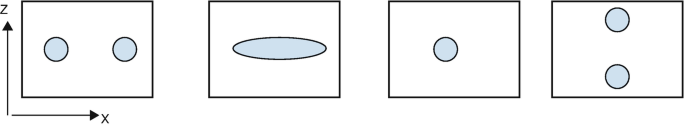
Stern Gerlach apparatus.
-
2.
 Would \(\lvert 0 \rangle \) and \(\lvert + \rangle \) together satisfy the criteria for a valid basis?
 -
3.
 An electron is in a superposition state shown in the geometric representation in Fig. 4.11.
Fig. 4.11 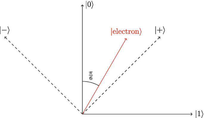
Superposition state of the electron.
-
(a)
What is the state of the electron in the z-basis? i.e. find α and β in \(\lvert \text{electron} \rangle = \alpha \lvert 0 \rangle + \beta \lvert 1 \rangle \)
-
(b)
What is the probability of measuring spin up?
-
(c)
What is the state of the electron in the x-basis? i.e, find α and β in \(\lvert \text{electron} \rangle = \alpha \lvert + \rangle + \beta \lvert - \rangle \).
-
(d)
What is the probability of measuring the spin in the \( \lvert - \rangle \) direction?
-
(a)
-
4.
 To measure the difference between an electron in a spin state \(\frac {1}{\sqrt {2}}\lvert 0\rangle + \frac {1}{\sqrt {2}}\lvert 1\rangle \) and one in \(\frac {1}{\sqrt {2}}\lvert 0\rangle - \frac {1}{\sqrt {2}}\lvert 1\rangle \), one could use:$$\displaystyle \begin{aligned} \begin{array}{rcl} \text{(I)} & &\displaystyle \text{A horizontal SGA.}\\ \text{(II)} & &\displaystyle \text{A vertical SGA.}\\ \text{(III)} & &\displaystyle \text{A}\ 45^\circ\ \text{diagonal SGA.} \end{array} \end{aligned} $$
-
(a)
I only
-
(b)
II only
-
(c)
I or III
-
(d)
II or III
-
(e)
I, II, or III
-
(a)
-
5.
 An electron with random spin is sent through two vertical SGAs as shown in Fig. 4.12. What would be the output of the second SGA?
Fig. 4.12 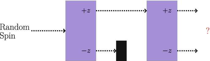
SGA setup for Problem 5.
-
6.
 An electron with random spin is sent through two vertical SGAs, where the second SGA is rotated upside down, or 180∘.
 -
7.
 An electron with random spin is sent through a horizontal SGA followed by a vertical SGA as in Fig. 4.15. What would be the output of the second SGA?
Fig. 4.15 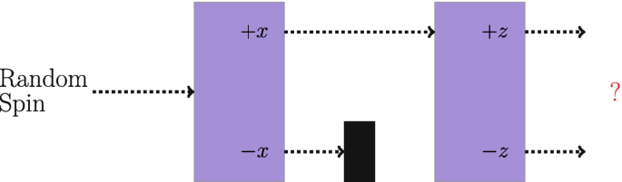
SGA setup for Problem 7.
-
8.
 An electron with random spin is sent through three SGAs as shown in Fig. 4.16. What would be the output of the third SGA?
Fig. 4.16 
SGA setup for Problem 8.
-
9.
 An electron with random spin is sent through three SGAs as shown in Fig. 4.17. What would be the output of the third SGA?
Fig. 4.17 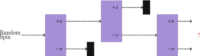
SGA setup for Problem 9.
-
10.
 An electron with random spin is sent through four SGAs as shown in Fig. 4.18. What would be the output of the fourth SGA?
Fig. 4.18 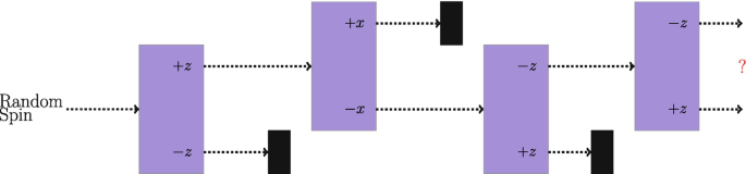
SGA setup for Problem 10.
 The Stern–Gerlach apparatus is rotated by 90∘ so that the magnetic field is in the x-direction as shown in Fig.
 Would
Would  An electron is in a superposition state shown in the geometric representation in Fig.
 To measure the difference between an electron in a spin state
  An electron with random spin is sent through two vertical SGAs as shown in Fig.
 An electron with random spin is sent through two vertical SGAs, where the second SGA is rotated upside down, or 180∘.

 An electron with random spin is sent through a horizontal SGA followed by a vertical SGA as in Fig.
 An electron with random spin is sent through three SGAs as shown in Fig.
 An electron with random spin is sent through three SGAs as shown in Fig.
 An electron with random spin is sent through four SGAs as shown in Fig.
Notes
- 1.
See https://en.wikipedia.org/wiki/Spin_(physics) for more details.
- 2.
- 3.
- 4.
- 5.
These two properties can also be used to form a basis in a classical system, where states should be swapped for vectors.
- 6.
Author information
Authors and Affiliations
Rights and permissions
Open Access This chapter is licensed under the terms of the Creative Commons Attribution 4.0 International License (http://creativecommons.org/licenses/by/4.0/), which permits use, sharing, adaptation, distribution and reproduction in any medium or format, as long as you give appropriate credit to the original author(s) and the source, provide a link to the Creative Commons license and indicate if changes were made.
The images or other third party material in this chapter are included in the chapter's Creative Commons license, unless indicated otherwise in a credit line to the material. If material is not included in the chapter's Creative Commons license and your intended use is not permitted by statutory regulation or exceeds the permitted use, you will need to obtain permission directly from the copyright holder.
Copyright information
© 2021 The Author(s)
About this chapter

Cite this chapter
Hughes, C., Isaacson, J., Perry, A., Sun, R.F., Turner, J. (2021). Creating Superposition: Stern–Gerlach. In: Quantum Computing for the Quantum Curious. Springer, Cham. https://doi.org/10.1007/978-3-030-61601-4_4
Download citation
DOI: https://doi.org/10.1007/978-3-030-61601-4_4
Published:
Publisher Name: Springer, Cham
Print ISBN: 978-3-030-61600-7
Online ISBN: 978-3-030-61601-4
eBook Packages: Physics and AstronomyPhysics and Astronomy (R0)