
Abstract
Oscillators deliver an essentially sinusoidal output waveform without input excitation. They are used in a wide range of applications including testing, communication systems and computer systems. Frequencies range from about 10−3 Hz to 1010 Hz, and in many applications a low distortion is required. There are two main classes of oscillators; RC oscillators in which the frequency determining elements are resistors and capacitors and LC oscillators in which the frequency-determining elements are inductors and capacitors. RC oscillators operate from very low frequencies up to about 10 MHz, making them very useful for audio frequency applications, while LC oscillators are useful for frequencies above about 100 kHz, and they are usually used in communications applications. This chapter explores the basic principles governing this class of circuits. The conditions required for oscillation are investigated and frequency and amplitude stability studied. At the end of the chapter, the student will be able to:
Access this chapter
Tax calculation will be finalised at checkout
Purchases are for personal use only
Bibliography
J. Millman, C.C. Halkias, Integrated Electronics: Analog and Digital Circuits and Systems (Mc Graw Hill Book Company, New York, 1972)
U. Tietze, C. Schenk, Advanced Electronic Circuits (Springer-Verlag, Berlin, 1978)
Author information
Authors and Affiliations
Problems
Problems
-
1.
State the Barkhausen criterion and discuss its meaning with respect to producing oscillation in a system.
-
2.
For the network shown in Fig. 12.60 determine the frequency at which phase shift through the network is zero and the magnitude of the associated transfer function at that frequency. Using this network design an oscillator to oscillate at a frequency of 15 kHz.
-
3.
Design a Wien bridge oscillator to oscillate at 10 kHz, and explain how a low-power incandescent lamp can be used to achieve amplitude stabilization.

Circuit for Question 1
-
4.
For the circuit shown in Fig. 12.61, find the frequency at which the output signal Vo is in phase with the input signal Vi and the transfer function value at this frequency. Hence design an oscillator using this circuit to have an oscillating frequency of 7 kHz.
-
5.
Draw the circuit of a phase shift lead oscillator, and describe its operation, referring to the Barkhausen criterion.
-
6.
Design a phase shift lead oscillator to oscillate at 5 kHz, and explain why this circuit is not suitable for a variable frequency oscillator.

Circuit for Question 4
-
7.
For the circuit shown in Fig. 12.62, determine showing all analysis the ratio RB/RA in order to achieve oscillation and the frequency of the oscillation. Hence design an oscillator using this circuit to have an oscillating frequency of 15 kHz
Fig. 12.62 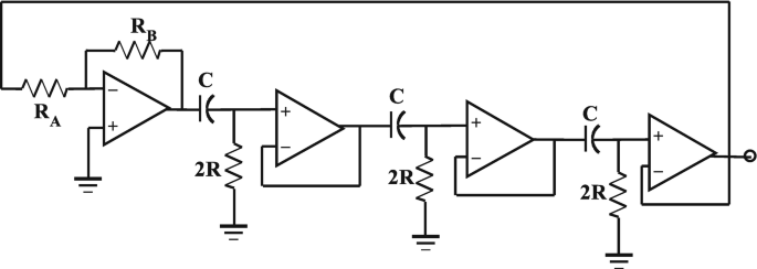
Circuit for Question 7
.

-
8.
For the circuit shown in Fig. 12.63, determine the inverting amplifier low-frequency gain in order to produce oscillation and the frequency of that oscillation. Hence design an oscillator using this circuit to have an oscillating frequency of 9 kHz.
-
9.
Draw the circuit of the Meacham oscillator, and briefly explain its operation. Using an operational amplifier, design a Meacham oscillator having an oscillating frequency of 6 kHz, and explain how oscillation can be maintained.
-
10.
Draw the circuit of a crystal oscillator using an operational amplifier as the active element. If the crystal is replaced by an inductor and capacitor in parallel, determine the condition for oscillation and the oscillating frequency of the circuit.

Circuit for Question 8
-
11.
For the circuit shown in Fig. 12.64 determine the ratio RB/RA for oscillation and the frequency of that oscillation. Using this circuit, design an oscillator with an oscillating frequency of 18 kHz.

Circuit for Question 11
-
12.
For the circuit shown in Fig. 12.65 determine the ratio R2/R1 in order to produce oscillation and the frequency of that oscillation. Hence design an oscillator using this circuit to oscillate at a frequency of 15 kHz.
-
13.
Design an LC resonant oscillator to operate at 50 kHz. Use a 2N3819 JFET and a 20-volt supply.
-
14.
Design an LC resonant oscillator using the AD844 to operate at 15 kHz.
-
15.
Explain the operation of the Hartley oscillator. Design a Hartley oscillator to operate at 50 kHz using a 2N3819 JFET. Use a supply voltage of 24 volts.
-
16.
Explain the operation of the Colpitts oscillator. Design a Colpitts oscillator to oscillate at 50 kHz using a 2N3819 JFET. Use a supply voltage of 24 volts.
-
17.
Determine the required capacitor, CT, to adjust the frequency of the Colpitts oscillators in Question 16 to 55 kHz.
-
18.
Using the circuit in Fig. 12.24, design a simple LC oscillator to oscillate at a frequency of 5 kHz.
-
19.
Design a crystal oscillator to oscillate at 75 kHz using an OP42 operational amplifier.
-
20.
Design a Miller oscillator using a 2N3918 JFET to oscillate at 110 kHz. Use a 25-volt supply.

Circuit for Question 12
Rights and permissions
Copyright information
© 2021 Springer Nature Switzerland AG
About this chapter

Cite this chapter
Gift, S.J.G., Maundy, B. (2021). Oscillators. In: Electronic Circuit Design and Application. Springer, Cham. https://doi.org/10.1007/978-3-030-46989-4_12
Download citation
DOI: https://doi.org/10.1007/978-3-030-46989-4_12
Published:
Publisher Name: Springer, Cham
Print ISBN: 978-3-030-46988-7
Online ISBN: 978-3-030-46989-4
eBook Packages: EngineeringEngineering (R0)