
Abstract
System quality is assessed with respect to the value of relevant properties of that system. The level of abstraction of these properties can be very high (e.g. usability) or very low (e.g. all the “Ok” buttons in the application have the same size). These properties can be generic and thus applicable to a large group of systems (e.g. all the interactive systems should be usable) or very specific to a system (e.g. the “Quit” button in my application should always be visible). While properties identification and verification is at the core of interactive systems engineering, much less attention is paid to properties that aims at characterizing a pair (or more) of systems. In this paper, we propose to study such properties (defined as across-systems properties) and propose a notation for representing them. We propose a process for the analysis of such properties using the proposed notation. This process and analysis can be used during systems design or integration. We also present several examples of across-systems properties and demonstrate their importance and use on a simple example of aircraft cockpits buttons.
You have full access to this open access chapter, Download conference paper PDF
Keywords
- Properties
- Within-system properties
- Across-systems properties
- Interactive systems
- Notation
- Aircraft cockpits
1 Introduction
The term property conveys multiple meanings in different domains. However, in computing systems domain [18], they are used to describe characteristics that the system should exhibit but their assessment (on a given system) is usually a complex and cumbersome activity. Formal description techniques are aimed at describing both the system and their expected properties and to demonstrate (or not) that the system really exhibits these properties.
Figure 1 presents the process advocated by DO178-C standard [22] for the design of computing systems in the aeronautics domain. That process highlights the need for explicit representation of expected properties for a given aircraft system (bottom of the Figure) and the formal methods supplement to this standard [17] even recommend the use of CTL (Computational Tree Logic) from [21] to represent them. The right-hand side of the Figure highlights the activity of formal verification that checks whether properties hold on the behavioral description of the system produced in the LLR phase (upper part of the Figure). Such approach follows the work done by Sistla and Pnueli [19] on the safety and liveness properties of reactive systems. Their focus, and the one of DO 330 standard, is on the representation of multiple properties for a single system under design or evaluation.

Formal Approach to System Design as in DO178C– Supplement 330 on Formal Methods [17]
The HCI community usually focusses on properties that characterize a single system in relation to the user and his/her environment. For instance, the well-studied usability property determines the effectiveness, the efficiency and the satisfaction according to standard ISO 9241 [7] of the system for a given user (or set of users). Other usability definitions add learnability [12] or accessibility [14] to the standard definition. Usability evaluation can be performed on one single system. In other words, the usability evaluation function needs one parameter (a system) and returns a set of value. This means that for usability evaluation would blend a value for the effectiveness of the system, a value for the efficiency of the system and one for the satisfaction of the user using the system. One important aspect of this is that the type of the values depends on the property. It can be Boolean (the property is true or false) but also enumerated type or a number (e.g. error rate). We call within-system property this kind of property for which the evaluation function needs one single system as parameter. User Experience [15], privacy [5], dependability and security [2] are other examples of within-system properties that can be evaluated on a single system. In contrast, other systems properties can be evaluated only with, at least, two systems as parameter. For instance, similarity property determines the distance between several interfaces in terms of orientation, order and density of their items (according to the definition in [6]). The evaluation function of similarity needs at least two parameters (two user interfaces) and returns a set of three values: one for the orientation, one for the order and one for the density. We call this kind of properties across-systems properties. Proximity [16] and congruence [3] are other examples of across-systems properties, as their evaluation function needs at least two parameters too. Less attention is paid to across-systems properties even though these properties can be extremely useful to characterize sets of systems as, for instance, in the prototyping phases of interactive systems development where multiple alternatives are designed and assessed. We propose to investigate and define different across-systems properties and a mean to describe explicitly these properties in interactive systems design process.
In the next section, we detail different examples of across-systems properties. In the third section, we propose QSCA notation supported by the DREAMER tool to represent across-systems properties. In the fourth section, we propose a process for the analysis of across-systems properties of systems using QSCA notation. The fifth section illustrates how this notation and process help in describing the across-systems properties of aircraft cockpit elements. Section 5 concludes the paper and highlights directions for future work.
2 Examples of Existing Across-Systems Properties
Across-systems properties are meant to characterize the quality of a set of systems. As mentioned in the introduction, Similarity is an across-systems property that aims at assessing the distance between the visual layouts of several systems interfaces in terms of orientation, order and density as introduced in [6], refined in [11] and more recently used for experience gathering [23]. This Similarity property can be included as a contributing factor of the Proximity property. The term Proximity is used by Wickens and Carswell [16] as compatibility principle between sets of displays for interface design. We propose to use the term Proximity as defined in [16] to be an across-systems property. The Proximity across-systems property is composed of Perceptual Proximity and Processing Proximity [16]. Perceptual proximity includes:
-
the spatial proximity of displayed items,
-
the visual connection between displayed items,
-
the similarity (e.g. color, orientation) between displayed items,
-
the homogeneous information display (i.e. all digital, all analogous, both),
-
the object integration (i.e. contiguity, contour and spatial integration) of displayed items.
Processing proximity includes:
-
the cognitive processing proximity of the tasks,
-
the similarity between units of the displayed parameters,
-
the temporal proximity of the task (i.e. the time to perform the task).
Another example of across-systems property is Congruence. Dekker and Hollnagel [3] define Congruence as the ability of the system to take into account the variation of user capabilities and needs depending on the current situation. Extending this proposal, we propose to consider congruence across a set of systems. In other words, Congruence property aims at characterizing the ability of a set of systems to maintain their input/output compatible with user capabilities and needs whatever the situation.
Finally, we propose a list of across-systems properties that are initially within-system properties but that can also be applied as across-systems properties:
-
Equivalency: One or several systems exhibit the same properties as another system or several systems.
-
Dependency: One or several systems depend on the outputs of other systems. For instance, a set of radio receptors are dependent from a radio transmitter, as receptors need the radio waves of the transmitter.
-
Complementarity: Each system belonging to a set of systems performs a share of the overall activity. The complete work is the union of each part. For instance, a set of factory robots of production line highly support complementary property, as each robot completes the work produced by the previous one.
-
Diversity: Each system of the set of systems is implemented in a different language or technology. A set composed of a C++ application, a JAVA application and a Python application highly supports diversity property [24].
-
Redundancy: Each system of the set of systems offers the same functions. For instance, a set composed of a computer extinguisher application and an extinguisher physical button of the computer highly support redundancy property for the shutdown function [26].
-
Equality: The control authority is equally distributed between the systems of the set. For instance, a set of systems under the so-called “master-slave” protocol have a very low equality property.
-
Uniformity: Each system of the set contributes with the same amount of work to the overall activity.
-
Concurrency: Each system of the set of systems work at the same time [25].
Defining properties of set of systems is useful to analyze how to integrate several systems for a particular function or to replace a system by another one inside an integrated set of systems. For example, in aircrafts, to integrate a system as a backup in case of a failure of another system, redundancy and diversity are important properties (that are related to the implementation of fault tolerance mechanisms [2, 4]). Another example is the replacement of a system by a newest one in a factory. In order to minimize the learning time for the operators, the proximity property has to be assessed (to ensure that the required number of new cognitive tasks to learn is low). In the same way that within-system properties may be used to define requirements for the systems and then drive the design of these systems, across-systems properties also may be targeted during the design of an integrated set of systems. In order to provide support for the comparison of design options with respect to a set of across-systems properties, we propose to extend TEAM design rationale notation (which is based on QOC [9]).
3 QSCA Notation: Extensions to the QOC and TEAM Notations
MacLean et al. [9] introduced the QOC (Question Option Criteria) notation for system design rational. QOC allows to document design choices with their explanations during the design process. This notation is also a tool for reasoning and communicating with various stakeholders as it uses very simple concepts. The TEAM (Traceability, Exploration and Analysis Method) [10] notation extends the QOC notation with the description of properties and factors associated to the criteria, as well as with the identification of design artefacts associated to the design options.
We propose to extend the TEAM notation to enable the representation of across-systems properties, in order to take into account across-systems properties when designing a set of systems. For that purpose, we propose to slightly adapt the TEAM notation to create QSCA notation:
-
Question: Design question about the system under design (Square in Fig. 2).
Fig. 2. 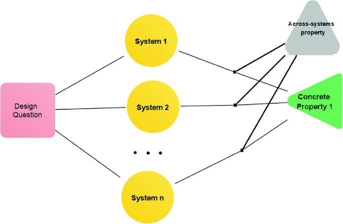
Main elements of the QSCA notation (extension to the notation TEAM) edited with the DREAMER tool
-
System: possible option for the system to answer the design question (Disc in Fig. 2) replaces design option of the TEAM notation.
-
Concrete property: Desired property met (or not) by the related set of systems (Lower right triangle in Fig. 2) replaces the desired property met by one or several design options of TEAM notation.
-
Across-systems property (Upper right triangle in Fig. 2) encompassing the concrete property of several systems. If a system option highly supports an across-systems property, a plain line is drawn between this across-systems property and the line that connect a system option and the concrete property associated to this across-systems property. If a system option gives few support to an across-systems property, a dashed line is drawn between this across-systems property and the line that connect a system option and the concrete property associated to this across-systems property. Across-systems property replaces the notation element Argument of the TEAM notation. The notation element Argument stands for the reason behind the choice of one design option in the TEAM notation.

The DREAMER (Design Rationale Environment for Argumentation and Modeling and Engineering Requirements) tool supports recording, edition and analysis of TEAM models [10]. We propose to use DREAMER to describe QSCA models.
4 From the Across-Systems Properties Description to a Process for the Analysis of Across-Systems Properties of Systems
In this section, we present the process for the analysis of across-systems properties of systems. This process presented in Fig. 3 can be used for various purposes during the design process (e.g. design choices or integration of systems).

Process for analysis of across-systems properties of systems.
During the first step, the involved stakeholders identify the design question related to the object of the analysis. For example, a design question can be “what are the most similar systems?”. They describe this design question in the QSCA model. During the step 2, they select the systems to compare. They describe these systems in the QSCA model. During the step 3, they identify the across-systems properties they want the selected systems to support. They identify the contributing factors of the selected across-systems properties as well. In the same way as the selection of within-system properties, the selection of across-systems properties can result from user studies, organizational or legal constraints. As for within-systems properties, it is possible that only some of the contributing factors of the across-systems property are identified relevant to support. For example, the appearance and identification contributing factors of UX within-system property can be identified relevant to the detriment of others during a user study. In the same way, the similarity of users tasks contributing factor of Proximity across-systems property can be identified relevant to the detriment of the others contributing factors. They describe the selected across-systems properties and/or across-systems property contributing factors in the QSCA model. During the step 4, they select the concrete properties to be measured on selected systems. For example, a concrete property of Similarity across-systems property is “same interface items orientation”. They describe these concrete properties in the QSCA model. During the step 5, they produce the final QSCA model. They describe how (strongly denied, denied, neutral, supported, strongly supported) the combinations of systems support each concrete property in the QSCA model and how these concrete properties support their relative across-systems properties. During step 6, they identify the combinations of systems that achieve across-systems properties. As a result, at the end of the process, the list of combinations of systems that achieve the across-systems properties is identified.
For the illustrative example of this paper, we follow this process and use the DREAMER tool [10] to analyze across-systems properties of different system designs of the FIRE push-button in an aircraft cockpit.
5 Representing Across-Systems Properties: Illustrative Example
In the A350 aircraft cockpit, there are guarded FIRE push-buttons on the overhead panel, one for each engine of the aircraft. These buttons are composed of a backlighting system, a guard and a toggle button (see Fig. 4). When a fire is detected in an engine, the backlighting system turns on and the pilot must raise the guard and press the toggle button [1] to acknowledge the alarm. When the button is pressed, all the systems that are connected to the engine are isolated and the fire extinguisher bottles are armed for a possible discharge [1].

Engine 1 FIRE push-button on the overhead panel.
In this example, we study the digitalization of such FIRE push-button (FIRE pb). Two different designs of the digital FIRE pb are proposed.
The first design option mimics all the graphical aspects and interactions of the physical FIRE pb. The difference is that the button is no more physical and user interactions must be performed with a mouse. The sequence of interaction is visible in Fig. 5. Like the physical FIRE pb, the user sees the backlighting system on, raises the guard and presses the button to isolate the engine and to prepare the bottles to discharge. We call this design option “overhead panel-like FIRE pb”.

Interactions sequence for pushing overhead panel-like FIRE push button
The second design option supports a different interaction sequence that still enables the guard of the button. This interaction sequence is similar to the GoProFootnote 1 unlock interaction and is called GoPro-like FIRE pb. This sequence of interactions is presented in Fig. 6 and is composed of the following steps: the user sees the backlighting system on, drags the button on the bolt area, maintains the button in this area until the animation finishes, releases and presses the button to isolate engine and prepare the bottles to discharge. For this proposed interaction design, the attention has been paid to respect the same interaction time to remove the guard and press the button as with the physical FIRE pb.

Interactions sequence for pushing GoPro-like FIRE push-button
We propose to analyze these different designs with the physical FIRE pb with respect to a subset of the across-systems properties presented in Sect. 2 in order to choose a digital design for the FIRE push-button. This goal is described by “which user control to perform an acknowledgment of fire?” design question (step 1 of the process described in Fig. 3). The systems to be compared are the physical, the overhead panel-like and GoPro-like fire push-buttons (step 2 of the process).
For this illustrative example, we choose to compare the push-buttons relative to their processing proximity, homogeneous information display, temporal proximity (contributing factors of Proximity across-systems property), redundancy and similarity (across-systems properties) (step 3 of the process). We choose “same graphical rendering”, “same functions”, “same time to perform tasks”, “same logical processing”, and the type of the output (physical and digital) as concrete properties to be measured on push-buttons (step 4). We describe in the QSCA model (Fig. 7) how the combinations of push-buttons support or not the concrete properties (step 5). The actual FIRE pb and overhead panel-like FIRE pb have the same graphical rendering. Then, they support the Similarity across-systems property (first multi-systems property from the bottom of Fig. 7) (step 6). All the systems have the same functions: fire alert, isolate engine and prepare the fire extinguisher bottles to discharge. Then, these systems support the Redundancy across-systems property (second multi-systems property from the bottom of Fig. 7) (step 6). All the systems are designed so that it takes the same time to perform the button push. Then, they support the temporal proximity across-systems property (step 6). The physical FIRE pb is physical whereas overhead panel-like and GoPro-like FIRE pb are digital. Then, they provide low support to the homogeneous information display across-systems property (step 6). Finally, all systems require the same logical processing user task: the button can be pushed to prepare fire extinguishing when the backlighting system is on and guard raised. Then, all the systems support the processing proximity across-systems property (step 6).

Representation of across-systems properties of FIRE pb, GoPro-like FIRE pb and overhead panel-like FIRE pb using extended QOC & TEAM notations to answer the design question “Which user control to perform acknowledge fire action?”
Across-systems properties can inform the design option decision if a single digital option must be chosen. In order to not modify the pilot training procedure as applied with the current physical FIRE pb, the preferred option should be the overhead panel-like FIRE pb one. Indeed, all of the design options are graphically alike and user cognitive tasks are close (similarity and processing proximity). Otherwise, despite the use of different input devices and interactions techniques used for the three design options, their across-systems properties indicate that they are alike. In this case, usability evaluation can be performed to discriminate the most suitable option according to the users.
6 Conclusion
This position paper introduces the concept of across-systems properties and proposes a mean to represent across-systems properties using QSCA notation based on TEAM and a process. It illustrates (on an example) how one can use it. This example is based on the physical FIRE push-button found in an aircraft cockpit and on its digital design alternatives (if we consider that future cockpits would replace such physical buttons with touch screen interactions). Even though, the physical FIRE push-button and digital alternatives seem to be very different, across-systems properties highlights their common characteristics and suitability to pilot tasks. In addition, if designers want to replace the current system by a digital one or want to integrate a redundant one, the representation of across-systems properties can guide design choices depending on the properties designers want to preserve and the ones they are ready to abandon.
In the same way as the pilot does not only use the FIRE push-button to deal with an engine fire (they could do testing for instance), it is common for users to manipulate several systems to reach a goal. In other words, users can use complex systems composed of several sub-systems to perform their work. For instance, an office employee use several systems such as a computer, a telephone and a printer to perform his/her work. All these systems compose a workstation complex system. For this reason, it might be interesting to investigate possible links between within-system properties of systems and across-system properties of the entire work environment. For instance, redundancy across-system property is also a fault tolerant technique to contribute to the within-system dependability [2] of a given system. Looking at each redundant component, we might want to identify within-system properties (e.g. performance). The variants used for redundancy must exhibit similar behaviors and thus similarity is, for them, an across-system property. If similarity is guaranteed then the fault-tolerant system embedding all the redundant ones will exhibit dependability as a within-system property.
One perspective to this work lays in the analysis of how within-system properties can help designers when they have to integrate several systems. For example, if several systems of the cockpit have a high proximity, the integration of these systems to support a user goal may enhance the usability of the whole cockpit, as pointed out by Huchins in the work on distributed cognition [27]. In other words, the description of the relationship between within-system properties and across-system properties can enable to understand how the first influences the second and to design systems with a more global integrated perspective.
Notes
References
Airbus A350 Flight Crew Operating Manual, 5T1 A350 FLEET FCOM. Technical Report. Airbus
Avizienis, A., Laprie, J.C., Randell, B., Landwehr, C.: Basic concepts and taxonomy of dependable and secure computing. IEEE Trans. Depend. Secure Comput. 1, 11–33 (2004). https://doi.org/10.1109/TDSC.2004.2
Dekker, S., Hollnagel, E.: Coping with Computers in the Cockpit. Routledge, Abingdon (2018)
Fayollas, C., Martinie, C., Navarre, D., Palanque, P., Fahssi, R.: Fault-tolerant user interfaces for critical systems: duplication, redundancy and diversity as new dimensions of distributed user interfaces. In: Proceedings of the 2014 Workshop on Distributed User Interfaces and Multimodal Interaction, pp. 27–30. ACM, New York (2014). https://doi.org/10.1145/2677356.2677662
Gerber, P., Volkamer, M., Renaud, K.: Usability versus privacy instead of usable privacy: Google’s balancing act between usability and privacy. SIGCAS Comput. Soc. 45, 16–21 (2015). https://doi.org/10.1145/2738210.2738214
Heil, S., Bakaev, M., Gaedke, M.: Measuring and ensuring similarity of user interfaces: the impact of web layout. In: Cellary, W., Mokbel, M.F., Wang, J., Wang, H., Zhou, R., Zhang, Y. (eds.) WISE 2016. LNCS, vol. 10041, pp. 252–260. Springer, Cham (2016). https://doi.org/10.1007/978-3-319-48740-3_18
International Standard Organization: “ISO 9241-11” Ergonomic requirements for office work with visual display terminals (VDT) – Part 11 Guidance on Usability (1996)
Lazar, J., Feng, J.H., Hochheiser, H.: Research Methods in Human-Computer Interaction. Morgan Kaufmann, Burlington (2017)
MacLean, A., Young, R.M., Bellotti, V.M.E., Moran, T.P.: Questions, Options, and Criteria: Elements of Design Space Analysis. Human-Computer Interaction. 6, 201–250 (1991). https://doi.org/10.1080/07370024.1991.9667168
Martinie, C., Palanque, P., Winckler, M., Conversy, S.: DREAMER: a design rationale environment for argumentation, modeling and engineering requirements. In: Proceedings of the 28th ACM International Conference on Design of Communication. pp. 73–80. ACM, New York (2010). https://doi.org/10.1145/1878450.1878463
Navarre, D., Palanque, P., Hamon, A., Della Pasqua, S.: Similarity as a design driver for user interfaces of dependable critical systems. In: Clemmensen, T., Rajamanickam, V., Dannenmann, P., Petrie, H., Winckler, M. (eds.) INTERACT 2017. LNCS, vol. 10774, pp. 114–122. Springer, Cham (2018). https://doi.org/10.1007/978-3-319-92081-8_11
Nielsen, J.: Usability Engineering. Elsevier, Amsterdam (1994)
Oxford Dictionary. https://en.oxforddictionaries.com/definition/property
Petrie, H., Kheir, O.: The relationship between accessibility and usability of websites. In: Proceedings of the SIGCHI Conference on Human Factors in Computing Systems. pp. 397–406. ACM, New York (2007).
Pirker, M.M., Bernhaupt, R.: Measuring user experience in the living room: results from an ethnographically oriented field study indicating major evaluation factors. In: Proceedings of the 9th European Conference on Interactive TV and Video, pp. 79–82. ACM, New York (2011)
Wickens, C.D., Carswell, C.M.: The proximity compatibility principle: its psychological foundation and relevance to display design. Hum. Factors: J. Hum. Factors Ergon. Soc. 37, 473–494 (1995)
DO-333 Formal Methods Supplement to DO-178C and DO-278A, published by RTCA and EUROCAE, 13 December 2011
Manna, Z., Pnueli, A.: A hierarchy of temporal properties. ACM Symp. Principles Distrib. Comput. 1990, 377–410 (1990)
Sistla, A.P.: On characterization of safety and liveness properties in temporal logic. In: Proceedings of the Fourth Annual ACM Symposium on Principles of Distributed Computing, pp. 39–48. ACM (1985)
Pnueli, A.: Applications of temporal logic to the specification and verification of reactive systems: a survey of current trends. In: de Bakker, J.W., de Roever, W.-P., Rozenberg, G. (eds.) Current Trends in Concurrency. LNCS, vol. 224, pp. 510–584. Springer, Heidelberg (1986). https://doi.org/10.1007/BFb0027047
Clarke, E., Emerson, E.A.: Design and synthesis of synchronization skeletons using branching time temporal logic. In: Logic of Programs: Workshop, Yorktown Heights, NY, May 1981, vol. 131 (1981)
DO-178C/ED-12C, Software Considerations in Airborne Systems and Equipment Certification, published by RTCA and EUROCAE (2012)
Zhao, X., Littlewood, B., Povyakalo, A.A., Strigini, L., Wright, D.: Conservative claims for the probability of perfection of a software-based system using operational experience of previous similar systems. Reliab. Eng. Syst. Saf. 175, 265–282 (2018)
Gashi, I., Povyakalo, A., Strigini, L.: Diversity, Safety and Security in Embedded Systems: Modelling Adversary Effort and Supply Chain Risks. EDCC 2016, pp. 13–24 (2016)
Best, E.: Semantics of Sequential and Parallel Programs. Prentice Hall International series in computer science, Prentice Hall, pp. I-XI, pp. 1–351 (1996), ISBN 978-0-13-460643-9
Avizienis, A.: The Methodology of N-version Programming. In: Lyu, M. (ed.) Software Fault Tolerance. Wiley, Hoboken (1995)
Hollan, J., Hutchins, E., Kirsh, D.: Distributed cognition: toward a new foundation for human-computer interaction research. ACM Trans. Comput. Hum. Interact. 7(2), 174–196 (2000)
Author information
Authors and Affiliations
Corresponding author
Editor information
Editors and Affiliations
Rights and permissions
Copyright information
© 2020 IFIP International Federation for Information Processing
About this paper

Cite this paper
Bouzekri, E., Canny, A., Martinie, C., Palanque, P. (2020). Characterizing Sets of Systems: Representation and Analysis of Across-Systems Properties. In: Abdelnour Nocera, J., et al. Beyond Interactions. INTERACT 2019. Lecture Notes in Computer Science(), vol 11930. Springer, Cham. https://doi.org/10.1007/978-3-030-46540-7_9
Download citation
DOI: https://doi.org/10.1007/978-3-030-46540-7_9
Published:
Publisher Name: Springer, Cham
Print ISBN: 978-3-030-46539-1
Online ISBN: 978-3-030-46540-7
eBook Packages: Computer ScienceComputer Science (R0)