
Abstract
The six components σx, σy, σz, τxy, τxz and τyz of the state of stress at a point in terms of a given cartesian coordinate system were defined in Chap. 2. In a state of plane stress, the only nonzero components are σx, σy and τxy. Let the x ‐ y plane lie in the plane of the page, with the z axis directed out of the page. Let a second cartesian coordinate system x′y′z′ be superimposed on the xyz system, then its orientation by rotating it about the z′ axis through a counterclockwise angle θ. By passing an oblique plane through a cubic element with its faces perpendicular to the xyz system and applying the equilibrium equations, expressions are obtained for the stress components σx′, σy′ and τx′y′ in terms of θ. Because of their importance in design, the maximum and minimum values of the normal stresses and the maximum value of the magnitude of the shear stress on any plane through the point are discussed. A graphical procedure known as Mohr’s circle, which helps in visualizing and interpreting the equations for determining the components σx′, σy′ and τx′y′ in terms of θ, is described. Attention is then given to the problem of determining the maximum and minimum normal stresses and the magnitude of the maximum shear stress for a general state of stress. The normal stresses are given by a cubic equation whose coefficients are functions of the components of stress. Its three solutions are called the principal stresses. The maximum magnitude of the shear stress is given by an expression in terms of the principal stresses. A special case called triaxial stress, in which the only nonzero stress components are σx, σy and σz, is discussed. Two applications giving rise to interesting states of stress, bars subjected to combined loads and pressure vessels, are then covered. The chapter closes with a discussion of the tetrahedron argument, which allows determination of the normal and shear stresses acting on any plane through a point in terms of the state of stress at the point.
Access this chapter
Tax calculation will be finalised at checkout
Purchases are for personal use only
Author information
Authors and Affiliations
Appendices
Chapter Summary
7.1.1 Components of Stress
In terms of a given coordinate system, the state of stress at a point p of a material is specified by the components of stress:
The directions of these stresses, and the orientations of the planes on which they act, are shown in Fig. (a). The shear stresses τxy = τyx, τyz = τzy and τxz = τzx.


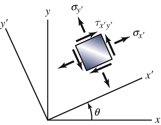
7.1.2 Transformations of Plane Stress
The stress at a point is said to be a state of plane stress if it is of the form
In terms of a coordinate system x′ y′ z′ oriented as shown in Fig. (b), the components of stress are


7.1.3 Maximum and Minimum Stresses in Plane Stress
The orientation of the element on which the principal stresses act (Fig. (c)) is determined from the equation


The values of the principal stresses can be obtained by substituting θp into Eqs. (7.6) and (7.8). Their values can also be determined from the equation
although this equation does not indicate the planes on which they act.
The orientation of the element on which the maximum in-plane shear stresses act (Fig. (d)) can be determined from the equation
or by using the relation θs = θp + 45°. The normal stresses σs acting on this element are shown in Fig. (d). The value of the maximum in-plane shear stress can be obtained by substituting θs into Eq. (7.7). Its value can also be determined from the equation
although this equation does not indicate the direction of the stress on the element.


The absolute maximumshear stress (the maximum shear stress on any plane through p) resulting from a state of plane stress is
7.1.4 Mohr’s Circle for Plane Stress
Given a state of plane stress σx, τxy, and σy, establish a set of horizontal and vertical axes with normal stress measured to the right along the horizontal axis and shear stress measured downward along the vertical axis. Plot two points, point P with coordinates (σx, τxy) and point Q with coordinates (σy, −τxy). Draw a straight line connecting points P and Q. Using the intersection of the straight line with the horizontal axis as the center, draw a circle that passes through the two points (Fig. (e)). Draw a straight line through the center of the circle at an angle 2θ measured counterclockwise from point P. Point P′ at which this line intersects the circle has coordinates \( \left({\sigma}_{x^{\prime }},{\tau}_{x^{\prime }{y}^{\prime }}\right), \) and point Q′ has coordinates \( \left({\sigma}_{y^{\prime }},-{\tau}_{x^{\prime }{y}^{\prime }}\right), \) as shown in Fig. (f).


7.1.5 Principal Stresses in Three Dimensions
For a general state of stress, the principal stresses are the roots of the cubic equation
where the stress invariants are
The absolute maximum shear stress resulting from a general state of stress is
The state of stress at a point is said to be triaxial if it is of the form
In triaxial stress, x, y, and z are principal axes, and σx, σy, and σz are the principal stresses. The absolute maximum shear stress in triaxial stress is
7.1.6 Tetrahedron Argument
Given the state of stress at a point p, the components of the tractiont at p acting on a plane through p whose orientation is defined by a perpendicular unit vector n (Fig. (g)) are
The normal stress at p is
and the magnitude of the shear stress is


Review Problems
-
7.106∗
The components of plane stress at a point p of a drill bit are σx = 40 ksi, σy = −30 ksi, and τxy = 30 ksi, and the components referred to the x′ y′ z′ coordinate system are \( {\sigma}_{x^{\prime }}=12.5\ \mathrm{ksi},{\sigma}_{y^{\prime }}=-2.5\ \mathrm{ksi} \), and \( {\tau}_{x^{\prime }{y}^{\prime }}=45.5\ \mathrm{ksi}. \) What is the angle θ?
Problems 7.106–7.107
-
7.107
The components of plane stress at a point p of the drill bit referred to the x′ y′ z′ coordinate system are \( {\sigma}_{x^{\prime }}=-8\ \mathrm{MPa},{\sigma}_{y^{\prime }}=6\ \mathrm{MPa} \), and \( {\tau}_{x^{\prime }{y}^{\prime }}=-16\ \mathrm{MPa}. \) If θ = 20°, what are the stresses σx, σy, and τxy at point p?
-
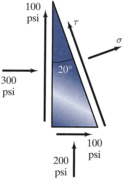
7.108
Determine the stresses σ and τ (a) by writing equilibrium equations for the element shown and (b) by using Eqs. (7.6) and (7.7).
Problems 7.108–7.109
-
7.109
Solve Problem 7.108 if the 300-psi stress on the element is in tension instead of compression.
-
7.110
For the state of plane stress σx = 8 ksi, σy = 6 ksi, and τxy = −6 ksi, what is the absolute maximum shear stress?
-
7.111
For the state of plane stress σx = 240 MPa, σy = −120 MPa, and τxy = 240 MPa, what is the absolute maximum shear stress?
-
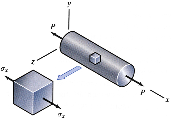
7.112
The components of plane stress acting on an element of a bar subjected to axial loads are shown. The stress σx = 4000 psi. Consider a plane through the bar whose normal is 20∘ relative to the x axis. Use Mohr’s circle to determine the normal stress and the magnitude of the shear stress on the plane.
Problem 7.112
-
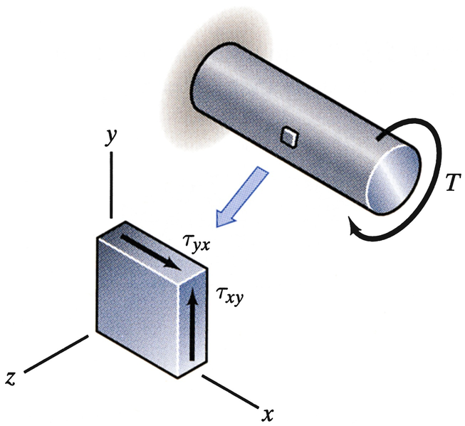
7.113
The components of plane stress acting on an element of a bar subjected to torsion are shown. The stress τxy = 4000 psi. Use Mohr’s circle to determine the principal stresses to which the material is subjected.
Problem 7.113
-
7.114
A machine element is subjected to the state of triaxial stress σx = 300 MPa, σy = −200 MPa, σz = −100 MPa. What is the absolute maximum shear stress?
-
7.115∗
At a point p, a material is subjected to the state of stress (in MPa):
$$ \left[\begin{array}{ccc}{\sigma}_x& {\tau}_{xy}& {\tau}_{xz}\\ {}{\tau}_{yx}& {\sigma}_y& {\tau}_{yz}\\ {}{\tau}_{zx}& {\tau}_{zy}& {\sigma}_z\end{array}\right]=\left[\begin{array}{rrr}4&2&1\\ {}2& -2&1\\ {}1&1& -3\end{array}\right] . $$Determine the principal stresses and the absolute maximum shear stress.
-
7.116
The cylindrical bar has radius R = 20 mm. It is subjected to a torque about its axis T = 60 N‐m and a couple My = 85 N‐m about the y axis in the direction shown. In terms of the coordinate system shown, determine the state of stress at point p, which is located at x = 60 mm, y = 0, z = 20 mm.
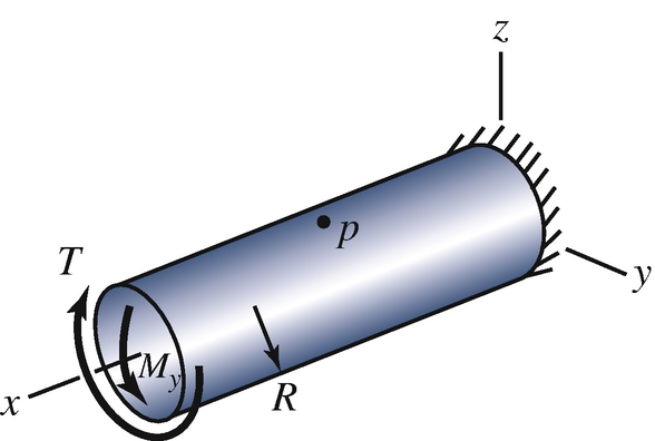
Problems 7.116–7.117
-
7.117
The cylindrical bar has radius R = 20 mm. It is subjected to a torque about its axis T = 60 N‐m and a couple My = 85 N‐m about the y axis in the direction shown. Determine the principal stresses and the maximum in-plane shear stress at point p, which is located at x = 60 mm, y = 0, z = 20 mm.
-
7.118
The beam is subjected to an axial load P = 1200 lb that does not act at the centroid of the cross section. The dimensions of the cross section are b = 4 in and h = 2 in. In terms of the coordinate system shown, determine the state of stress at point p, which has coordinates \( y=\frac{1}{2}h \) and \( z=\frac{1}{4}b \).
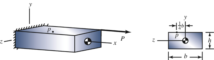
Problem 7.118
-
7.119
The spherical pressure vessel has a 1-m radius and a 0.002-m wall thickness. It contains a gas with pressure pi = 1.8E5 Pa, and the outer wall is subjected to atmospheric pressure po = 1E5 Pa. Determine the maximum normal stress and the absolute maximum shear stress at the vessel’s inner surface.
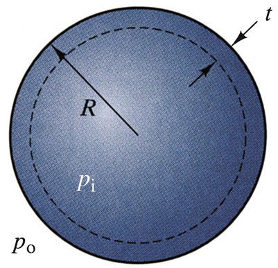
Problems 7.119–7.120
-
7.120
The spherical pressure vessel has a 1-m radius and a 0.002-m wall thickness. The allowable value of the absolute maximum shear stress is τallow = 14 MPa. If the outer wall is subjected to atmospheric pressure po = 1E5 Pa, what is the maximum allowable internal pressure?


Rights and permissions
Copyright information
© 2020 Springer Nature Switzerland AG
About this chapter
Cite this chapter
Bedford, A., Liechti, K.M. (2020). States of Stress. In: Mechanics of Materials. Springer, Cham. https://doi.org/10.1007/978-3-030-22082-2_7
Download citation
DOI: https://doi.org/10.1007/978-3-030-22082-2_7
Publisher Name: Springer, Cham
Print ISBN: 978-3-030-22081-5
Online ISBN: 978-3-030-22082-2
eBook Packages: EngineeringEngineering (R0)