
Abstract
Consider a straight, horizontal beam with arbitrary supports. Let a cartesian coordinate system be oriented with its origin at the centroid of the beam’s cross section, the x axis extending to the right along the beam’s axis, and the y axis upward. Assume that the external forces and couples on the beam and the reactions due to its supports exert a two-dimensional system of forces and couples in the x‐y plane. Let a plane be passed through the beam perpendicular to its axis, and consider the free-body diagram of the part of the beam to the left of the plane. The distribution of stress on the plane can be represented by an equivalent system consisting of two components of force and a couple. One of the force components is the axial force P perpendicular to the cutting plane, which is assumed to act at the centroid of the cross section and be positive in the positive x direction. The other force component is the shear force V tangential to the cutting plane, assumed to be positive in the negative y direction (downward). The couple is the bending moment M, assumed to be positive in the counterclockwise direction about the z axis. If the external loads on the beam and the reactions due to its supports are known, the equilibrium equations can be applied to the free-body diagrams on either side of the cutting plane to determine the internal forces and moment P, V, and M. Graphs of V and M as functions of x are called the shear force and bending moment diagrams, respectively. It can be shown that the shear force and bending moment in a beam subjected to a distributed load w satisfy the differential equations dV/dx = − w, dM/dx = V. In principle, these equations can be used to determine the shear force and bending moment as functions of x. The first equation is integrated to determine V, and then the second equation is integrated to determine x. In doing so, the effects of point forces and couples must be accounted for. A substantial complexity is that each time the equation describing the distributed force on the beam changes, or at each location where a point force or couple acts, a new free-body diagram must be used or new solutions of the two differential equations must be obtained. It would be convenient if the loading on an entire beam could be expressed by a single function. This can be done using what are called singularity functions. These are defined and it is shown how point forces are represented by delta functions, couples are represented by dipoles, and distributed forces are represented by Macaulay functions. Examples of using singularity functions to determine the shear and bending moment diagrams are presented.
Access this chapter
Tax calculation will be finalised at checkout
Purchases are for personal use only
Author information
Authors and Affiliations
Appendices
Chapter Summary
5.1.1 Axial Force, Shear Force, and Bending Moment
If the system of external loads and reactions on a beam is two-dimensional, the internal forces and moments can be represented by an equivalent system consisting of the axial force P, the shear force V, and the bending moment M (Fig. (a)). The directions of P, V, and M in Fig. (a) are the established positive directions of these quantities. The shear forceand bending moment diagrams are simply the graphs of V and M, respectively, as functions of x.


5.1.2 Equations Relating Distributed Load, Shear Force, and Bending Moment
In a segment of a beam that is subjected only to a distributed load (Fig. (b)), the shear force is related to the distributed load by


If there is no distributed load throughout the segment, the shear force is constant. If w is a constant throughout the segment, the shear force diagram for the segment is a straight line. The change in the shear force between two positions xA and xB is equal to the negative of the area defined by the loading curve between those positions:
Where a beam is subjected only to a point force of magnitude F in the positive y direction, the shear force diagram undergoes an increase of magnitude F (Fig. (c)). Where a beam is subjected only to a couple, the shear force diagram is unchanged (continuous).
In a segment of a beam subjected only to a distributed load, the bending moment is related to the shear force by


The change in the bending moment between two positions xA and xB is equal to the area defined by the shear force diagram between those positions:
Where a beam is subjected only to a counterclockwise couple of magnitude C, the bending moment diagram undergoes a decrease of magnitude C (Fig. (d)). Where a beam is subjected only to a point force, the bending moment diagram is unchanged.
5.1.3 Singularity Functions
The loads on a beam can be expressed as a distributed load in terms of the singularity functions summarized in Table 5.1. A delta function exerts a downward force of unit magnitude at x = a. A dipole exerts a counterclockwise couple of unit magnitude at x = a. The most common distributed loads can be expressed in terms of Macaulay functions. Once the loads on a beam are expressed as a distributed load in terms of singularity functions, Eq. (5.5) can be integrated to determine the shear force, and Eq. (5.7) can be integrated to determine the bending moment as functions of x.
Review Problems
-
5.67
(a) Draw the free-body diagram of the beam by isolating it from its supports. (b) Determine the reactions at the supports. (c) Determine the internal forces and moment at C by drawing the free-body diagram of the part of the beam to the left of C.
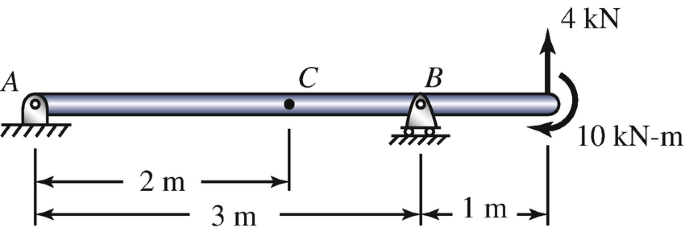
Problems 5.67–5.68
-
5.68
Determine the internal forces and moment at point C by drawing the free-body diagram of the part of the beam to the right of C.
-
5.69
If x = 3 m, what are the internal forces and moment at C?
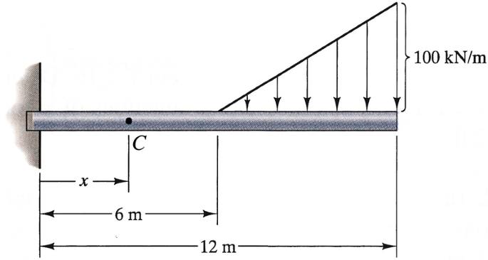
Problems 5.69–5.70
-
5.70
If x = 9 m, what are the internal forces and moment at C?
-
5.71∗
The loads F = 200 N and C = 800 N‐m. (a) By drawing free-body diagrams and applying the equilibrium equations, determine the internal forces and moment as functions of x. (b) Draw the shear force and bending moment diagrams.
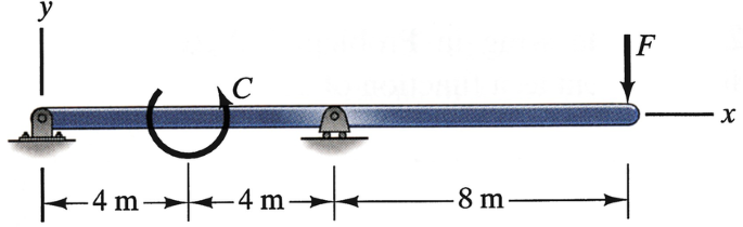
Problems 5.71–5.72
-
5.72∗
The beam will safely support shear forces and bending moments of magnitudes 2 kN and 6.5 kN-m, respectively. Based on this criterion, can it safely be subjected to the loads F = 1 kN, C = 1.6 kN‐m?
-
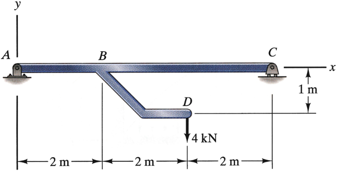
5.73
The bar BD is rigidly fixed to the beam ABC at B. Draw the shear force and bending moment diagrams for the beam ABC.
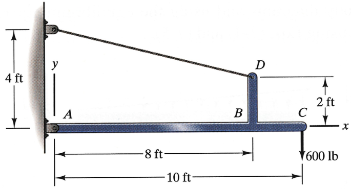
Problem 5.73
-
5.74∗
(a) By drawing free-body diagrams and applying the equilibrium equations, determine the internal forces and moment as functions of x for beam ABC. (b) Draw the shear force and bending moment diagrams.
Problem 5.74
-
5.75
Use singularity functions to solve Problem 5.71.
-
5.76
Use singularity functions to solve Problem 5.74.


Rights and permissions
Copyright information
© 2020 Springer Nature Switzerland AG
About this chapter
Cite this chapter
Bedford, A., Liechti, K.M. (2020). Internal Forces and Moments in Beams. In: Mechanics of Materials. Springer, Cham. https://doi.org/10.1007/978-3-030-22082-2_5
Download citation
DOI: https://doi.org/10.1007/978-3-030-22082-2_5
Publisher Name: Springer, Cham
Print ISBN: 978-3-030-22081-5
Online ISBN: 978-3-030-22082-2
eBook Packages: EngineeringEngineering (R0)