
Abstract
If a common hacksaw blade is held between the palms and a gradually increasing compressive load is applied, it quickly collapses into a bowed shape. This is an example of column buckling; the blade fails as a structural element under compressive loads that are tiny compared to the compressive loads necessary to cause yielding of the steel blade. The chapter begins with the derivation of the buckling load of a pin-ended prismatic bar subjected to compression, known as the Euler buckling load. In theory, the bar can buckle into a one-half cycle sine shape (the familiar bowed shape), a full cycle sine shape, a one-and-one-half cycle sine shape, etc., with increasing corresponding buckling loads. These different solutions are called buckling modes. (As intuition indicates, the higher modes are unstable and the bar actually buckles in the first mode.) Analyses are presented of the buckling of bars with other types of end conditions, which can greatly affect the resulting buckling load. A concept known as the effective length is introduced. Suppose that a given column buckles in a particular mode and the buckling load is P. The effective length is the length of a column whose Euler buckling load equals P. In some cases, the effective length of a buckled column can be determined or approximated by observation and used to determine the buckling load. The final topic is the behavior of a bar subjected to eccentric axial loads, that is, loads that are a specified distance from the centroid of the cross section. Such bars do not buckle but assume a bowed shape whose maximum deflection increases with the magnitude of the axial load. An expression for the maximum compressive stress in the bar, known as the secant formula, is derived.
Access this chapter
Tax calculation will be finalised at checkout
Purchases are for personal use only
Author information
Authors and Affiliations
Appendices
Chapter Summary
10.1.1 Buckling Loads
The buckling load for a prismatic column of length L that is free at the ends and buckles as shown in Fig. (a) is called the Eulerbuckling load:
Figure (a) is the first buckling mode for a column that is free at the ends. The distributions of the deflection for the second, third, and fourth modes are shown in Fig. 10.5. The buckling load of the nth mode is
First-mode buckling loads of columns with other common end conditions are shown in Fig. 10.16.


10.1.2 Effective Length
Suppose that a given column buckles in a particular mode and the buckling load is P. The effective length Le is the length of a column of the same flexural rigidity whose Euler buckling load equals P:
The ratio of the effective length to the column’s actual length is denoted by K and called the effective length factor:
For example, if a column of length L that is free at the ends buckles in the second mode, the effective length is Le = L/2 (Fig. (b)). The effective length factor is
and the buckling load is
In some cases, the effective length of a buckled column can be determined or approximated by observation, and Eq. (10.21) can be used to determine the buckling load.


10.1.3 Eccentric Loads and the Secant Formula
Consider a prismatic column that is free to rotate at the ends and is subjected to eccentric loads (Fig. (c)). The distribution of the deflection is
and the maximum deflection is
where λ2 = P/EI.


The maximum compressive stress in the column in Fig. (c) is given by the secant formula
where \( k=\sqrt{I/A} \) is the radius of gyration of the cross section. The parameter ec/k2 is the eccentricity ratio and L/k is the slenderness ratio. When the column’s dimensions, the modulus of elasticity, and the eccentricity are known and the maximum allowable compressive stress is specified, Eq. (10.32) can be solved numerically for the maximum allowable axial load.
Review Problems
-
10.55
The column is steel with elastic modulus E = 220 GPa. Determine its Euler buckling load.
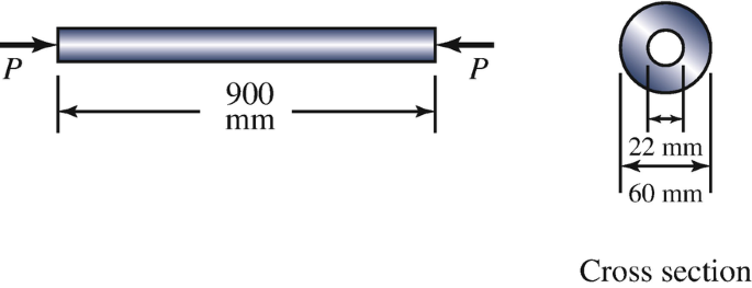
Problems 10.55–10.56
-
10.56
The column is steel with elastic modulus E = 220 GPa. Determine its second-mode buckling load.
-
10.57
The bar AB consists of material with elastic modulus E = 70 GPa. It has a hollow circular cross section with radii Ro = 20 mm and Ri = 8 mm. Can a horizontal force F = 120 kN be applied at A without causing bar AB to fail by buckling?
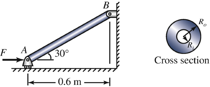
Problems 10.57–10.58
-
10.58
Suppose that the circular cross section of the bar AB has an outer radius Ro = 20 mm and you want to choose the inner radius Ri so that bar AB will buckle when F = 100 kN. What is the radius Ri?
-
10.59
The column supports an axial load P. The dimensions of its rectangular cross section are b = 180 mm and h = 360 mm. The column has a fixed support at its base. The support at the top allows rotation, prevents lateral deflection in the x–y plane, and allows lateral deflection in the x–z plane. The elastic modulus is E = 200 GPa. What is the column’s buckling load? Does it buckle by bending in the x–y plane or the x–z plane?
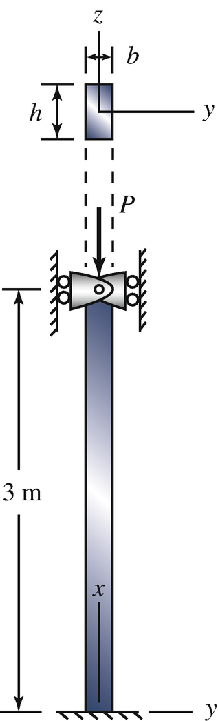
Problems 10.59–10.60
-
10.60
Suppose that you want to choose the dimensions b and h of the cross section of the column so that the buckling load of the column if the buckles by bending in the x–y plane is equal to the buckling load if it buckles by bending in the x–z plane. Determine the necessary value of the ratio h/b.
-
10.61
The cylindrical tube is subjected to eccentric axial loads P = 120 kN. It consists of aluminum alloy with modulus of elasticity E = 72 MPa. What is the maximum resulting deflection?
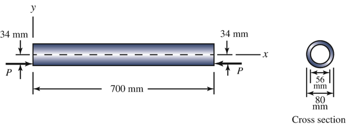
Problems 10.61–10.62
-
10.62
The cylindrical tube is subjected to eccentric axial loads P = 120 kN. It consists of aluminum alloy with modulus of elasticity E = 72 MPa. What is the maximum normal stress in the tube?


Rights and permissions
Copyright information
© 2020 Springer Nature Switzerland AG
About this chapter
Cite this chapter
Bedford, A., Liechti, K.M. (2020). Buckling of Columns. In: Mechanics of Materials. Springer, Cham. https://doi.org/10.1007/978-3-030-22082-2_10
Download citation
DOI: https://doi.org/10.1007/978-3-030-22082-2_10
Publisher Name: Springer, Cham
Print ISBN: 978-3-030-22081-5
Online ISBN: 978-3-030-22082-2
eBook Packages: EngineeringEngineering (R0)