
Abstract
Welding is an important process in manufacturing which enables large and complex shaped products to be divided into small and simple parts to be manufactured independently and later can be rigidly joined by fusion of the material at the interface between two metal pieces, stiff enough to operate as a single piece. Welding process is mainly characterized by the melting of the interface material between the two metals, fusion or mixing of the material and then solidifying to produce a rigid and high strength joint. In some cases or applications, even an axial or shear pressure may accompany the fusion phenomenon to trigger a plastic deformation of material at the interface for tight bonding. Some other important materials used in welding are filler metals and fluxes. Filler metals are employed to provide the same material (as that of the base metals) at the interface gap between them in molten condition. Fluxes are employed to remove oxide formations in the weld pool and other impurities and form a layer of slag above the molten pool, protecting it from further oxidation. In this chapter, the fundamental concept behind the various welding processes and how are these classified based on different heat source utilization and techniques of utilization are explained in detail.
1 Highlights
This chapter basically deals in the fundamental concepts of various techniques and processes employed in welding, the application of these processes and their classification based on different techniques of heat generation.
2 Introduction
There is a need of large size, complex and intricate shaped components that are difficult to manufacture as a single piece. To avoid such problems in material handling, the components are generally manufactured in parts which are much simpler to produce individually and can be later assembled by joining into the final products. Welding mainly employs the phenomenon of metal fusion at the interface between two fitted workpieces which upon solidification forms a rigid and strong joint. In many case, pressure is being applied along with the fusion process to produce a defect free and tight joint. Other joining process apart from welding, includes soldering, brazing, adhesives and mechanical fasteners. Soldering and brazing are employed when there is a need of a strong joint between two dissimilar metal without the fusion of the base metal and by only melting the filler metal to fill the gaps between the work pieces.
Welding processes like any other manufacturing process employ numerous techniques and types, each of which is unique in their utilization of the heat source, weld joint strength, ease of manufacture, welding speed and job materials. These processes can be mainly classified into 3 categories namely, fusion welding, solid state welding and soldering-brazing. Fusion welding basically utilizes the phenomenon of melting of metal surfaces at high temperature for joining and includes gas welding, arc welding, resistance welding, etc. On the other hand, in solid state welding the material is not melted by any heating source and the joining is done by applying external pressure or forces on the either side of the metal-metal interfaces. The extreme pressure deforms the interface material plastically to fuse together into one. Common examples of solid state welding are cold welding and friction welding. In the 3rd category, soldering and brazing employs the phenomenon of adhesion and diffusion between the molten filler metal and the faying surfaces of the fitted metal interface.
3 Welding Processes
Based on the characteristics of the heat source, welding processes can be classified into gas welding, arc welding, resistance welding, thermit welding, friction welding and laser beam welding. These are described in detail below.
3.1 Gas Welding
In Gas welding, dual gases are generally used which ignites to melt the metal around the joint forming an autogenous or homogenous weld joint. One of the gases is generally a fuel gas while the other gas is oxygen. Based on the combination of the type of these gases, gas welding can be distinguished into oxy-acetylene gas welding, air-acetylene gas welding and oxy-hydrogen gas welding. These are described below.
3.1.1 Oxy-acetylene Gas Welding
In oxy-acetylene gas welding, the acetylene is used as the fuel which is mixed with oxygen in desired proportion and released through the nozzle to produce different types of flames that are useful for joining different metals and alloys. Various ferrous and non ferrous metals are joined using this process and the equipment mainly consists of two cylinders (each of acetylene and oxygen), long hoses, welding torch, pressure gages and regulators. The weld torch releases the gases in desired proportion through the nozzle which ignites the flame. The flame is directed sharply over a narrow weld area to melt the metal around the joint and creating a fusion zone. The gases are delivered to the torch from the acetylene and oxygen cylinders via hoses and are connected to the pressure gages and regulators at the top of the cylinder to control the gas flow (Fig. 5.1).

Source Oxy acetylene welding (2008) Wikimedia commons
Oxy-acetylene welding [5].
The flames produced in the oxy-acetylene gas welding are of different types based on the amount of heat required to melt the joining metals and oxidizing properties of different metals. The reaction basically involves combustion of acetylene gas in presence of oxygen gas to produce heat, carbon-dioxide and water vapour as the final product. These are shown below [1]:
In the first reaction, the acetylene dissociates into carbon monoxide (CO) and hydrogen (H2), generating heat which is 1/3rd of the total heat produced and forming the inner core of the flame. In the second reaction, the carbon monoxide and hydrogen produced from the first reaction reacts again with the surrounding atmospheric oxygen for the final output products generating heat which is 2/3rd of the total heat. The temperature generally reaches to about 3300 °C in this process which is way above the melting temperature of most of the metals including the ferrous metals. As can be observed from the above equations, the ratio of the volumes of acetylene and oxygen is 1:1 which when supplied accordingly, there does not remain any extra oxygen and the concerned flame is termed the neutral flame. Neutral flames are generally used for welding majority of the ferrous and non ferrous metals including steel. When oxygen gas is released in excess, the metals to be joined especially steel tends to get oxidized around the weld region due to high temperature which is an undesirable outcome as it weaken the joint by forming oxides. This type of flame is called the oxidizing flame. Oxidizing flames are limited in its use and are generally used to join copper metals and alloys, the oxidized molten metal of which forms a protective layer on top of the weld pool, called slag [2]. The third type of flame is the reducing flame, which burns at a limited supply of oxygen producing low heat and high amount of soot. This flame is generally employed for low heat application such as soldering, brazing and flame hardening process.
An important material that is used which acts as a filler metal along the joints and are generally in the form of rods, sticks and wires, made of the same metal as that of the base metal and which is coated with flux. The forward end of the filler stick is placed on top of the joint, above which the flame is directed, melting the filler end to accumulate inside the weld pool, forming stiff joints upon solidification. The flux in the weld pool reacts with the surrounding oxides and other impurities which gets lighter and lifted up to the top of the weld pool surface preventing further oxidation. The flux also produces a gaseous envelope around the arc and weld region for shielding the molten metal from atmospheric oxygen.
3.1.2 Air-Acetylene Gas Welding
In air-acetylene gas welding, air is drawn into the torch, mixed with the fuel gas such as acetylene, propane, butane and natural gas, deriving the necessary oxygen from the air for combustion and igniting to produce flame. Since the heat produced is low, this welding process is employed for low melting temperature metals and alloys such as lead and for joining processes like brazing and soldering [3].
3.1.3 Oxy-hydrogen Gas Welding
In oxy-hydrogen gas welding, the setup is similar to oxy-acetylene gas welding with the only difference of installing a special regulator in the hydrogen metering unit and storing hydrogen in cylinder instead of acetylene. The heat produced in this case is low and therefore is employed for low melting temperature metals such as aluminium, magnesium and lead. The flame produced by hydrogen is not visible and so is difficult to adjust for the desired flame [3].
3.2 Arc Welding
With the development of the commercial electricity, people have started recognizing the potential of an arc between two electrodes produced by high voltage supply, to produce enough heat, raising the temperature of the medium between them to about 3900 °C. The earliest use of the welding process involved a carbon electrode and the workpiece served as the other electrode [4]. The arc between them produces heat which melts the workpieces to form rigid joints. The temperature of the arc depends on factors like current supplied, electricity supply type, voltage applied and the polarity of the current. The carbon electrodes were soon replaced by filler metal rods or wires (consumed in the process and having lower melting temperature than the arc temperature), whose properties are similar to the base metal with fluxes being provided in the wire for removal of impurities from the weld pool and protection from the atmospheric oxygen by formation of slag which remain floated above the fused region. This type of filler wires with a coating of flux and other elements are also called shielded metal electrodes which stabilizes the arc and protects the molten metal from oxidation. As the wire gets consumed gradually, proper feed mechanism is installed to maintain a constant stabilized arc length.
The temperature produced in the weld region by the arc can be controlled considering the polarity of the current in a DC supply. When the positive terminal of the DC supply is connected to the workpiece and negative terminal to the electrode, the temperature produced near the workpiece is maximum, facilitating quick melting of the metal joints. This is due to higher concentration of collision of electrons on the metal surface released through the arc from the negative electrode and this method is called straight polarity direct current (SPDC). Another alteration in characteristics of the welding process is observed when the positive terminal of the DC supply is connected to the electrode and negative to the work piece. This condition is called reverse polarity direct current (RPDC) which produces minimum heat near to the workpiece and vice versa near to the electrode end of the arc. Low melting temperature metals and alloys are generally welded using this method. Since, AC supply produces rapid fluctuation in the polarity of the current at high frequency, it distributes the heat generation equally towards both the ends of the arc.
The above described general welding process involves consumable electrodes, the materials of which get deposited in the weld pool by the heat of the arc. Another type of welding processes utilises tungsten electrodes which does not melt during the welding process but vaporizes slowly. These electrodes are called non consumable electrodes [4].
3.2.1 Arc Welding Processes with Consumable Electrodes
Below mentioned welding processes utilizes electrodes which are consumed by the heat of the arc and fills the weld pool producing a defect free and quality joints.
3.2.1.1 Metal Arc welding
Metal arc welding involves a bare metal (serving as a filler metal) electrode with special coating in case of a shielded metal arc welding and creating a shielding gas atmosphere in case of Gas metal arc welding [4].
In shielded metal arc welding (SMAW), a special coating around the metal electrode wire serves the purposes of providing various desirable functions such as arc stabilizing by vaporizing the coating material into shielding gas, removal of impurities from the molten weld pool (acting as a flux), preventing the molten pool from further oxidation by forming slag above it, reducing weld spatter, adding alloying elements, increasing efficiency of deposition of filler metal and enhancing penetration of heat for deeper welds. The special coatings can be of cellulose and titania which are composed of mainly SiO2, TiO2 with addition of small quantity of FeO, MgO and Na2O, and volatile materials. The volatile material releases hydrogen which might sometimes get dissolved into the weld pool causing embrittlements and cracks. Low hydrogen evolving coatings are available which eliminates this drawback and maintains a required level of shielding atmosphere around the arc and the weld pool. Electrodes are generally baked before using it for welding in order to remove the moisture content for limiting the evolving hydrogen during the reaction.
The operation of shielded metal arc welding involves touching of the electrode to the metal joint region to initiate the spark and then moving it back to maintain a stable arc length. The process is versatile and is economically efficient with low equipment cost. Stainless steel, carbon steel, alloy steel and cast steels are generally welded using this process and a welding voltage of about 15–45 V, welding current ranging between 10 and 500 A is utilized to produce an arc temperature of about 5000 °C. The filler metal wire has a diameter of about 1/16–1/4 in. and a length of about 9–14 in. (Fig. 5.2).

Source Equipment gas metal arc welding (2014) Wikipedia
Gas metal arc welding [6].
3.2.1.2 Metal Inert Gas Welding (GMAW)
In Gas metal arc welding (GMAW) or metal inert gas (MIG) welding, the bare metal wire used as electrode is similar to that in case of the shielded metal arc welding, the difference being in the fact that no coating has been provided in this welding process. Instead of the special coating in SMAW, all the various functions of arc stabilizing, penetration of the heat and protecting of the molten weld pool from the atmospheric oxidation are provided by gas shielding. The gases mainly used are inert and consist of a mixture of argon and helium (used for welding non ferrous metals) with addition of small amount of O2 and CO2 in case of ferrous metals.
The GMAW process is relatively fast and economical and there is no requirement of frequent alteration of electrodes as in the case of SMAW. No fluxes are required and hence no slag formation is triggered and concentrated heat quickly penetrates deep within the joints. It is due to this penetration capability, GMAW is generally used in reverse polarity direct current mode. Due to its smooth and clean weld formation and operational simplicity, the GMAW can be automated and robotic implementation is possible.
3.2.1.3 Submerged Arc Welding (SAW)
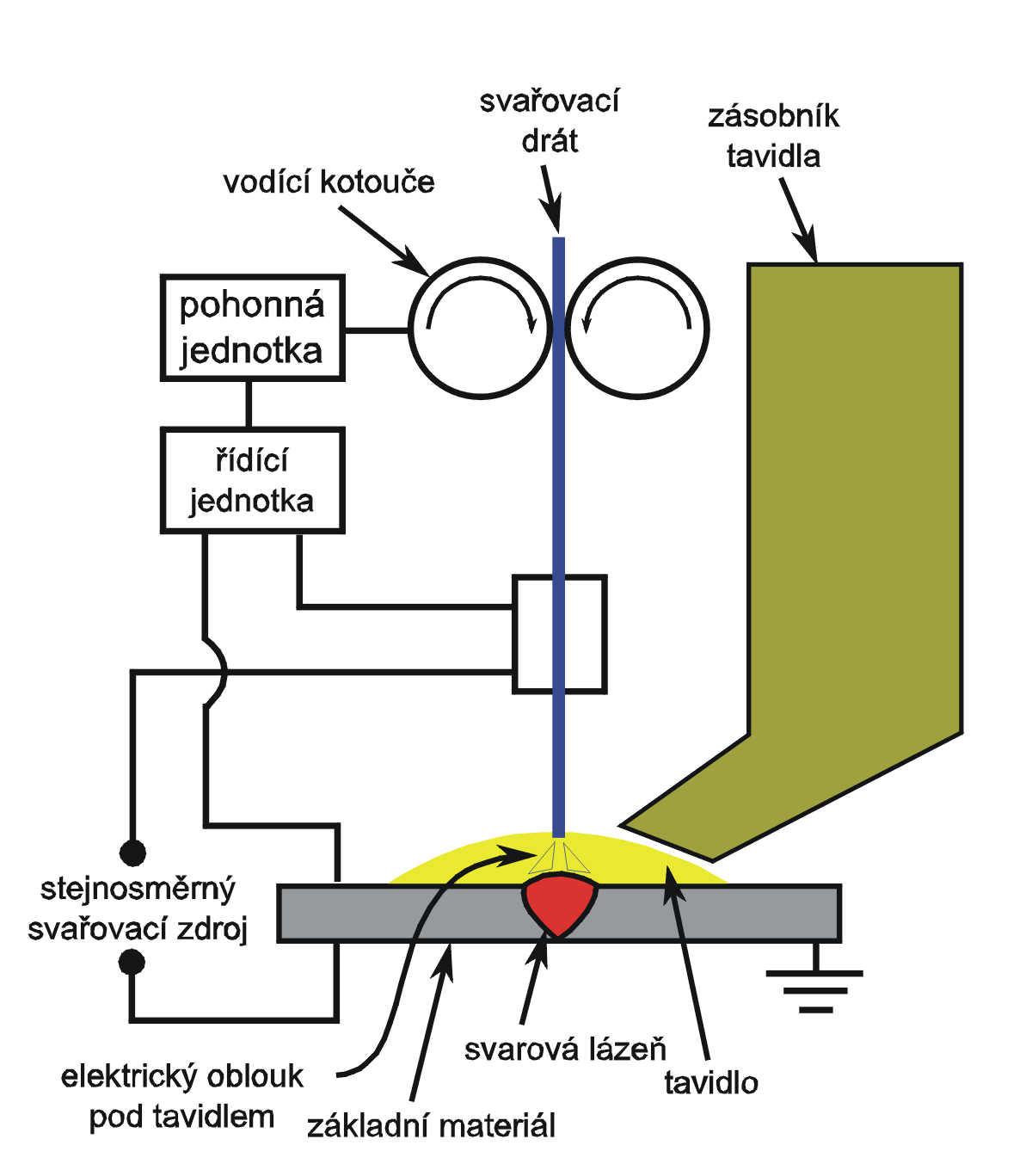
In submerged arc welding process, a bare metal electrode end is submerged inside the granular layer of fluxes (composed of lime, magnesium oxide, silica, calcium fluoride and other compounds) and electricity is switched on. The arc produced melts the electrode metal wire and a portion of the surrounding fluxes to get deposited into the weld pool. The deposited molten flux combines with the impurities in the weld pool to get lighter in weight which rises to the surface as slag. The remaining flux (including the molten flux layer on top of the weld pool and the un-melted portion of the flux granules) provides extra shielding from the atmospheric oxygen, preventing weld spatter, blocking ultraviolet radiations and fumes emitted in the process and lowers the rate of cooling of the metal in the joint to give a soft, ductile metal joint. The molten flux over the weld pool upon solidification becomes brittle and gets easily separated from the weld surface. A vacuum suction is used to remove the remaining unmelted flux granules which are then re-utilized for later processes. Since the fluxes and molten weld are held in its position under gravity, the process involves horizontal working (Fig. 5.3).

Source Submerged arc welding schematic (2010) Wikimedia commons
Submerged arc welding [7].
The suitable joints formed by submerged arc welding are butt joint and fillet joint. Multiple electrodes can also be used in this process when a higher deposition rate of welding is desired. Other significant characteristics of SAW are high welding speed, deeper penetration and clean operation. Electricity source used can be both DC and AC with currents ranging from 600 to 2000 A.
Submerged arc welding is mainly employed for welding low carbon steels but can also be used for medium carbon steel, cast irons, alloy steel, stainless steel, copper alloys and nickel alloys, with some pre and post welding measures.
Welding of high carbon steel, tool steel, aluminium, magnesium, lead, zinc and titanium are not recommended using this process due to unavailability of desired quality fluxes, high reactivity at higher temperature and low sublimation temperatures. Requirement of excess handling of fluxes and large volume of slag, need for horizontal placement of the workpieces, large grain structured joints obtained due to high temperature working and absorption of moisture by the flux materials (leading to porosity) are few other drawbacks of this process.
3.2.1.4 Electro Gas Welding
Electro gas welding is mainly employed for joining vertically placed pieces by their edges or in a butt joint technique using a special equipment consisting of a pair of water cooled shoes, one of which is fixed while the other moves vertically upward along the joint to be made (placed between the shoes) and at the same time depositing metal from a single flux cored electrode or single solid electrode (or multiple electrodes) into the weld pool by passing electric arc. The flux melted by the heat of the arc gets deposited in the weld pool and accumulates the impurities in the form of slag on top of the molten pool which is prevented from flowing out by the pair of shoes placed on either side of the joint. The slag provides protection to the molten metal from the atmospheric oxygen and the shielding is done by the gases evolved such as CO2, inert gases like argon and helium, etc. either from the cored flux or from external source.
Electro gas welding is extensively used in the construction of bridges, ships, thick and large diameter pipes, pressure vessels and storage tanks. Metals mostly welded using this process are structural steels, aluminium and titanium alloys. Apart from vertical edges, this process can also be employed for welding circumferential joints in large pipes by rotating it. The current for a flux cored electrode can reach up to 750 A while for a solid electrode it can reach up to 400 A with a power consumption of about 20 kW [1].
3.2.2 Arc Welding Processes with Non Consumable Electrodes
The arc welding processes that utilize electrodes which are not consumed by the heat of the arc produced and thus can be used for an extended period of time. These processes are described below.
3.2.2.1 Gas Tungsten Arc Welding (GTAW)
In GTAW, tungsten electrodes are used which is basically not consumed during the arc generation as in the case of any consumable electrodes and helps maintain a constant arc length throughout the operation. The shielding is done (without application of any flux material) by releasing inert gases like argon and helium around the weld region which prevents oxidation of the molten metal by contacting with the atmospheric air. The electricity supply used can be DC or AC depending on the nature of the metal to be joined. In case of DC supply, the current is kept at about 200 A while for AC supply, the current is kept at 500 A. The power supply ranges between 8 and 20 kW (Fig. 5.4).

Source GTAW setup (2005) Wikimedia commons
Gas tungsten arc welding [8].
For welding aluminium and magnesium, GTAW is commonly used with AC supply, the frequency of which has an effect on the cleaning of the weld surfaces by removing the oxides of these metals and impurities. This gives a good quality weld, defect free and smooth surface finish. Titanium and refractory metals are other materials which can be welded using GTAW.
A couple of major limitations of the GTAW are the contamination of the tungsten electrode during contact with the molten metal in the weld pool. This contamination effects the proper arc generation and can cause discontinuities in the weld bead. Another drawback is the cost of the inert gases is too high making it an expensive process. Some of the advantages of this process includes good surface characteristics of the weld surface or smooth surface finish is obtained, ability to weld a range of workpiece thicknesses and equipment portability.
3.2.2.2 Carbon Arc Welding
As already mentioned at the starting of the “arc welding” section, carbon (graphite) electrodes were the earliest used electrodes which generates an arc between the electrode and the workpiece to melt the workpiece edges, forming rigid joints. With the development of tungsten electrodes and application of these in welding processes like GTAW, PAW and AHW (atomic hydrogen welding), the use of carbon electrodes have almost declined which can otherwise be employed in brazing operations, repairing iron castings and depositing wear resistant materials on the surfaces.
3.2.2.3 Plasma Arc Welding (PAW)
Plasma arc welding involves an inert gas like argon which is passed through an orifice (between the tungsten electrode and the plasma gun or plasma nozzle) to produce a concentrated plasma gas on passing electric arc. This plasma beam can reach a temperature of up to 33,000 °C which can easily melt the edges of two metal plates fitted at a close proximity. The process begins with the generation of arc between the tungsten electrode and the plasma gun at the orifice which blocks the path of argon gas being forced to move through the orifice under a certain pressure. The argon gas absorbs the heat of the arc to ionize completely and in the process generates tremendous amount of energy in the form of plasma gas which moves down, transferring the energy to the workpiece for melting. Another opening around the plasma gas nozzle, releases shielding gas (argon or helium or mixture between them) which protects the molten weld pool from coming into contact with the atmospheric oxidation. The heat supplied to the workpiece depends on the pressure at which the plasma gases get released. With lower pressure of the plasma gas, the metal just gets melted and proper fusion and solidification of the weld region takes place. With increase in pressure, a depression begins to form on the surface of the weld pool leading to a keyhole through the joining metal plates just below the plasma orifice. With constant movement of the plasma gun along the metal joint, the keyhole formed is filled with the surrounding molten metal pool and solidifying upon cooling to form strong joint. As the pressure is increased to its maximum, the molten metal under the plasma orifice is thrown out from beneath (a keyhole) which is basically a plasma cutting operation (Fig. 5.5).

Source Non-transferred DC plasma torch (retrieved on 9th of April, 2019) Wikipedia
Non-transferred Plasma arc welding [9].
The above described plasma arc welding is basically a non-transferred plasma arc welding method which does not include the workpiece in its electrical circuitry and involves an arc produced between the tungsten electrode and the plasma gun nozzle with the heat being transferred to the workpiece by hot plasma gas. Another method called transferred plasma arc welding produces arc between the tungsten electrode and the workpiece, transferring heat directly.
Plasma arc welding finds its application in a variety of metals with part thicknesses not exceeding 6 mm and due to its advantageous characteristics like arc stabilizing, low distortion, concentrated heat supplied, deeper and narrow weld, the process is widely used for both butt and lap joints. Skilled personnel are required while carrying out operation in PAW.
3.3 Resistance Welding
In resistance welding, the heat energy required to melt the metal surfaces to be fused together for rigid joints, is obtained from the highly concentrated electrical resistance at various locations on the interface between the surfaces of the metal parts on passing electricity. Lap joints are mainly welded using resistance welding and electricity is passed between a pair of electrodes pressed tightly on top and bottom of the lap joint. With high resistance offered by interfaces between electrodes and metal surfaces, metal to metal surfaces and by the metal parts itself, the concentrated building of resistance between the electrodes heats up the metal-metal interface surfaces (at a small region) which melts to fuse together upon solidification. Since no contact with the atmospheric oxygen is made, the molten pool remains protected without the use of shielding gas and fluxes, provided the surface of the metals are cleaned and made free of any impurities (oils, paints, films, etc.) and oxide layers prior to the welding. There is also no requirement of filler metals as in the case of shielded arc welding processes or any other conventional welding processes.
Thermal conductivity and specific heat of the metals to be joined plays a vital role in deciding the temperature rise at the interface between them. Since in resistance welding, heat is concentrated around a small region or point, aluminium and copper metals are welded using resistance welding as they have higher thermal conductivities. Based on the type of electrodes used and methods implemented, resistance welding can be divided into resistance spot and seam welding.
In resistance spot welding, a pair of electrodes are used (tapered at the front) which are placed on either side of a lap joint (between two metal plates) and applies pressure during the time of current flow through the metal interface and remains pressed (forming a slight depression on the metal outer surfaces) until the molten bead solidifies at the interface. Then the pressure is released and moved to another position on the metal-metal interface for welding. The pressure may be applied by mechanical means (rocker arm type) or pneumatic means (press type) which are used for small and large workpieces respectively. Multiple pairs of electrodes can also be used simultaneously to perform spot welds and current provided through each pair ranges in (3000–40,000) A to obtain a weld nugget of 6–10 mm in diameter. The spot welding process is economical and easy to perform and the major application of this technology can be frequently seen in automobile industries and repairing shops.
Resistance seam welding is an extension of spot welding where the electrodes used are in the form of rotating and conducting wheels (and rollers) and continuous spot welds are being formed along the movement of the electrodes on the metal surfaces. AC current is generally used which on higher frequency (or slow rotational speed of the electrode wheels) produces continuous beads of spot welds, closely placed in the form of a seam. Resistance seam welding is mainly used for producing seam welds on cans, gasoline tanks and other household containers.
3.4 Laser Beam Welding (LBW)
Laser beam welding utilizes the heat from a high power concentrated laser beam to melt thin or thick metal interfaces for high strength joint. Due to high energy density of the beam, it has an excellent penetration characteristic and is generally used for producing narrow and deep joints of depth to width ratio ranging between 4 and 10. The joint produced is ductile, free from impurities, shrinkages or distortions and porosity, and the welding speed can vary from 2.5 m/min for thick metal joints to about 80 m/min for thin joints. For thin metal joints, power supplied by high energy dense laser beam ranges up to 100 KW with pulsed energy input in milliseconds. For thick metal joints, a multi KW continuous system of energy input is provided by the laser beam. LBW can be automated due to its processing nature, therefore minimum skill is required of the operator and can be performed in remote inaccessible locations. In automotive industries, LBW is mainly employed for welding of transmission components with high precision.
Laser beam welding has the advantage over electron beam welding in that it does not require vacuum atmosphere for operation, the beam can be optically focussed just like any other light beams so they are economical and can be robotized, weld quality is excellent with no porosity and complete fusion of metal joints takes place with no X-ray emission.
3.5 Friction Welding
Friction welding can be distinguished from all other welding processes by the fact that it does not require an external energy source for melting of the interface material in the welding procedure and can be directly joined, utilizing the frictional characteristics between two metal surfaces upon relative motion. The axis-symmetry piece of a pair of metal components is held on a rotating chuck while the other piece of metal (axis-symmetry or non axis-symmetry) remains stationary. The rotating piece is axially pressurized against the surface of the stationary piece of metal at a relative surface velocity of up to 15 m/s at the interface and when sufficient contact is made at the joint interfaces the rotation is suddenly bought to halt while the axial pressure compresses the plastic state of the material at the interface to form a properly fused strong joint. During the rotation of the workpiece at the interface the oxide layers gets eroded and thrown out radial by centrifugal action including all other impurities. A flash of material generally emerges out of the interface in radial direction due to plastic compression of the material and can be later machined out or grounded. The extent of the weld effected region in this process mainly depends on factors like conductivity of the metals to be joined, heat generated during frictional contact and mechanical properties of the metals (Fig. 5.6).

Source Rotary friction weld (2009) Wikipedia
Rotary friction welding [10].
Solid bars of diameter up to 100 mm, hollow cylinders having outer diameter of up to 250 mm and all other pairs of components consisting of at least a single piece of axis-symmetry work can be affordably and easily welded using friction welding.
3.6 Cold Welding
Cold welding is mainly employed by application of pressure at the interface between two dissimilar or similar (more preferable) metals without employing any heating source or frictional heat, but using pairs of rolls and dies. The process is completely based on the principle of plastic deformation and therefore it is desirable for at least a single metal piece to be ductile if not both of it. Since this process involves just the interface contact which merges into one on application of roll or die pressure due to plastic deformation and fusion, interface surfaces needs to be made free of oxide layers, contaminants, oil, grease and other particles, prior to the operation which ensures greater strength of the joint.
Joining of aluminium and steel by this process involves formation of intermetallic brittle compounds at the interface which makes the joint brittle and low in strength. Dissimilar metals that are mutually soluble into each other can produce weak joints leading to failure and due to which similar metal jobs are most preferred for this operation.
Roll bonding or roll welding is a common cold welding process which employs rolls (on either side of a sandwiched layers of two dissimilar or similar metals) to apply pressure on the surfaces to get bonded at desired locations on the interface that has been previously thoroughly cleaned. Common examples of roll bonding are bimetallic strips in thermos heaters and thermostats and roll welding of a layer of stainless steel on either surfaces of a mild steel [1].
Apart from the welding processes some other joining processes for metals and other materials are brazing, soldering and mechanical fastener.
3.7 Braze Welding
In brazing operation, a filler metal known as braze metal is used to fill the gaps between the two faying surfaces of the metal edges in molten condition without the melting of the base metals. The filler metal has a melting point of about 450 °C which is lower than the base metal (ensuring no melting of the base metal) and is melted by various external heat sources thus, penetrating into the gaps between the faying surfaces and later solidifying to produce high strength joints. Fluxes are used to remove oxides and impurities from the joint gap and are fed along with the filler molten metal into it. The filler metal used is generally made of brass and fluxes used are borax, fluorides, chlorides, boric acid and borates.
Braze welding is mainly employed for repairing works, joining intricate and lightweight shapes and for joining metals such as cast steel and iron. Thus with this process, joining between two dissimilar metals can be effectively performed having a good joint strength.
3.8 Soldering
Soldering is similar to brazing operation where filler metal in the form of solder (made of an alloy of tin and lead) is melted (using soldering torches and irons) along with the flux and then diffused into the gaps between two tightly fitted faying metal surfaces by capillary action. The flux reacts with the impurities and forms slag on the surface preventing oxidation of the joined metal surfaces. The filler metal upon solidification, thus make a high strength and defect free joint. One specific significant property of solder metal is its low surface tension or its wetting action which ensures proper filling of the gap between the metals (Fig. 5.7).

Source Soldering (2018) Pixabay
Soldering [11].
The melting point of solder alloy depends mainly on the composition and its eutectic point. Various other combination in alloys such as tin-zinc, zinc-aluminium, lead-silver and cadmium-silver are also commonly used as solder metal. As there is concern regarding the hazardous emission from lead compounds, solder alloys are generally nowadays lead free. Fluxes used can be inorganic acids and salts (zinc-ammonium-chloride solution), or resin based fluxes (used in electronic applications). When soldering is performed with inorganic acids and salts, the joints need to be made free of any flux residue from the surface to avoid corrosion.
3.9 Mechanical Fasteners
Mechanical fasteners include nut-bolts, nails, rivets, screws car bumper clips, mechanical seams, staples, stitches, crimping and any other specific mechanical fastening methods that involve formation of holes through both the mating metal pieces for a permanent or temporary joint.
4 Summary
From the above discussion, it is clear that simple to complex parts can be joined using traditional and advanced welding processes. Welding processes can be mainly classified into fusion welding, solid state welding and other joining processes like soldering and brazing. Fusion welding processes includes gas welding, arc welding and resistance welding which involves melting of the metal interfaces to fuse together forming a uniform strength joint but which varies in their heat sources. Gas welding employs thermal heat of the gases (oxygen and fuel gas) to melt the metal interfaces for fusion welding, arc welding employs heat from an electric arc to melt the metal at the interface using different modes of polarity (straight polarity direct current and reverse polarity direct current) and resistance welding employs resistance heat offered by the material of the metal pieces that has been lap jointed, between the two electrodes. Solid state welding includes friction welding and cold welding which does not require any heating source and can be joined while in a solid state. Friction welding employs heat generated by frictional stress subjected between the surfaces of the two joining metals and by plastic deformation. While on the other hand, cold welding involves application of pressure on top of a sandwiched layer of two metal parts. Soldering and brazing operations involve use of filler metals which melts and diffuses into the gap between tightly fitted metal plates. Mechanical fasteners are another mechanism of joining parts employing mechanical means.
References
Kalpakjian, S., & Schimid, S. R. (2009). Manufacturing, engineering and technology (p. 6). Prentice Hall.
Beddoes, J., & Bibby, M. J. (2003). Principle of metal manufacturing processes. Elsevier Butterworth Heinemann.
Hazra Choudhury, S. K., & Hajra Choudhury, A. K. (1986). Elements of workshop technology. In Manufacturing Processes (Vol. 1, No. 10). Media Promoters and Publishers Pvt. Ltd.
DeGarmo, E. P., Black, J. T., & Kohser, R. A. (2008). Materials and processes in manufacturing (p. 8). USA: Prentice Hall.
https://upload.wikimedia.org/wikipedia/commons/1/15/Oxy_acetylene_welding_rig.jpg.
https://upload.wikimedia.org/wikipedia/commons/e/e8/Equipment-gas-metal-arc-welding.png.
https://upload.wikimedia.org/wikipedia/commons/8/82/Submerged_arc_welding_schematic-cz.png.
https://upload.wikimedia.org/wikipedia/commons/5/5e/GTAW_setup.png.
https://upload.wikimedia.org/wikipedia/commons/b/bc/Nontransferred_DC_plasma_torch.png.
https://upload.wikimedia.org/wikipedia/en/d/dc/Rotary_friction_weld.jpg.
https://cdn.pixabay.com/photo/2018/04/01/06/13/soldering-3280085_960_720.jpg.
Author information
Authors and Affiliations
Corresponding author
Rights and permissions
Copyright information
© 2019 Springer Nature Switzerland AG
About this chapter

Cite this chapter
Kumar, K., Kalita, H., Zindani, D., Davim, J.P. (2019). Welding. In: Materials and Manufacturing Processes. Materials Forming, Machining and Tribology. Springer, Cham. https://doi.org/10.1007/978-3-030-21066-3_5
Download citation
DOI: https://doi.org/10.1007/978-3-030-21066-3_5
Published:
Publisher Name: Springer, Cham
Print ISBN: 978-3-030-21065-6
Online ISBN: 978-3-030-21066-3
eBook Packages: EngineeringEngineering (R0)