
Abstract
To meet a demand more and more personalized for different users, the products must be innovative but also reliable, modular with good maintainability. Considering all these requirements in the design and modeling process would facilitate an evaluation of the behavioral performance of the future product. Most works deal with aspects related to functional criteria whereas behavior is rarely taken into account in the search for solutions. In this paper, we propose a design approach for innovative modular products, easily maintainable and adaptable to different user profiles. In order to evaluate the modularity, we propose a method of semantic modeling. The semantic model obtained makes it possible to identify innovative modular solution concepts by solving technical contradictions taking into account both the functional characteristics and the behavioral performances. As an illustration, a case study is outlined.
You have full access to this open access chapter, Download conference paper PDF
1 Introduction
From the Russian acronym, TRIZ is a theoretical approach for inventive problem solving. Indeed, several works have been done in this direction, from the ontology proposal of the main notions of the concepts associated with the acquisition of knowledge [1], to the formal definition of the contradiction and its potential manipulations in the inventive conception according to the basic principles of TRIZ [2], the application of TRIZ to real industry problems [3] or the proposal for an integrated framework for systems to support individual creativity [4].
However, setting up a product requires consideration of several factors that will reflect the product. The complexity of the design lies in the fact that the products must be innovative and more efficient, that is to say more reliable, resistant, easy to assemble and disassemble, etc. It is in this sense that it is said in [5] that the designer must opt for product solutions that are simple to manufacture, ergonomic, very reliable, safe, easy to maintain and have an overall cost over the entire life cycle that is attractive to the consumer.
Being more and more complex, the products imply an interaction between several actors [6, 7]. Managing all the factors in the design process requires taking into account the environment and evaluating the performance of the future product or system [8, 9]. Thus, we intend to conduct a scientific and technical study to propose innovative products through a semantic modeling method and the identification of innovative modular solutions concepts by the resolution of technical contradictions. In this article, we propose to implement a semantic design approach for modularity and to identify innovation paths, in terms of both modularity and other product-related behaviors.
2 Start of the Art
Following a literature review [10,11,12], it should be said that design methodologies have been continuously improved in recent years. Thus it has been proposed in [13], the combination of the systemic model and the V-model. On the one hand, they focus on design and modeling, and on the other hand, they help to improve the evaluation of products in the early stages of their design [10]. Others have done a lot of research on design and methodologies [14, 15]. While some have highlighted the steps of the conceptual design of mechatronic products [16]. In addition, there are several product design models among which, V design, spiral design, unified methods, agile methods, etc., [17]. Being the result of the decomposition of a product or system, the modularity makes it possible to solve several aspects of the product manufacture. Various works have been carried out in this sense [18, 19] and approaches have been developed to make the systems modular and to simplify their links. Let us note generative grammars for generating and classifying the components or the use of the concept of “holons” to model the connections between structure and functions [19]. Boothroyd et al. [20] propose a systematic methodology to assess the influence of Geometry, Material, Tolerance effects on Assembly. In this methodology, the emphasis was to relate Product design, Assembly operations, and Assembly Method to the single decision factor: the cost. Hitachi Assembly Evaluation Method is another approach based on very similar principals. The basic idea is the reduction of cost of a product through simplification of its design by:
-
Reducing of number of components
-
Ensuring that parts are easy to assemble
-
Increasing the use of standardized parts across entire product range
-
Designing with widest possible tolerances
-
Material selection must consider manufacturing also, not just function.
Boothroyd-Dewhurst method includes:
-
Preliminary (rough) design
-
Selection of Assembly Method (manual, robotic, or high-speed automated)
-
Design/Redesign of product for selected method
-
The selection of assembly method must be done at an early stage in the product design process.
In most of these previous works, the authors highlight a structural and functional modularity of products or systems in order to obtain at a final product with a more flexible configuration. These different approaches were not intended to offer innovative and modular products in terms of new technological concepts. In this article we propose an approach of designing innovative and modular products based on the TRIZ method. Thus our design method allows to identify the problems, the solutions as well as the technical contradictions that result.
Our goal is to propose an innovative product design approach, modular, easily repairable and adaptable to different user profiles, we will in this article work on a semantic modeling method, in order to obtain modular solutions concepts innovative.
3 An Approach for Modularity Assessment
Starting from the conceptual design, the work in [6] defined a field of eligible solutions (instances, SS (Space of Solution), classes of solutions) respecting certain requirements and constraints as illustrated in the Fig. 1. We will consider a solution instance in the area of eligible solutions to highlight the modular aspect.

SS and DES
A solution instance will be represented by a graph G (C, L) with C the set of components and L the set of links. In this graph G (C, L), we have: C = {X1, X2, X3, X4} and L = {{X1, X2}, {X1, X3}, {X2, X4}, {X4, X2}} (Fig. 2).

Representation of a product instance by a graph G (C, L)
Moreover, to find the connected components, we will first build the adjacency matrix denoted M of the graph G and the matrix of the transitive closure of the same graph noted M *.

The adjacency matrix is obtained by noting:
-
✓ 1 if there is a relationship between two components
-
✓ 0 otherwise
Thus, we will be able to determine the matrix of the transitive closure denoted M *.
I: matrix unit (put on the main diagonal of the 1 and the rest we put 0) Mn−1: adjacency matrix (n−1) we stop at 3, since n = 4 for this graph So:

From the matrix of the transitive closure, we deduce the following connected components: {X1}, {X2}, {X3} and {X4} because the lines are not alike, which is why each line is considered as a component related in itself. To calculate the modularity of an instance, we will use analogy based on the cyclomatic number to determine the complexity of a program (computer) by counting the number of paths. The cyclomatic number is defined by the following equation:
with
- M::
-
cyclomatic complexity
- E::
-
the number of edges of the graph
- N::
-
the number of nodes of the graph
- P::
-
the number of connected nodes of the graph
In software engineering, a simple code with a low cyclomatic number is theoretically considered as easier to read, test and maintain.
It is in this same logic that fits our approach to define a product modularity with the same equation:
where
- M::
-
Modularity of the product
- E::
-
the number of links between components of the product
- N::
-
the number of components of the product
- P::
-
the number of connected components of the product
For that we will take into account two graphs representing two instances of products, then will determine the most modular between these 2 products. If we consider a first graph G (C, L) in Fig. 3, the connected components of the graph G are: {X1}, {X2}, {X3}.

Graphs (G (C, L)−G′ (C′, L′))
Then, consider a second graph G′ = (C′, L′) whose connected components: {X1, X2, X3}.
Modularity M
-
For the graph G we will have:
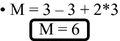
-
For the graph G’ we will have:
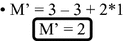


M′ < M so the solution M′ is theoretically more modular
In the next section, we discuss about the influence of the different parameters involved in the modularity expression.
4 Discussion and Contradictions in Design for Modularity
To improve the modularity it is necessary that the value of M is the smallest possible. When is the best modularity for a product reached? If we take the example above, it should be said that M’ of the graph G’ is more modular since it is less than M of the graph G. However if we come to find that the value of M is equal to 1 (M = 1), but we will have a monobloc product. On the other hand, if we increase the value of M by acting on its parameters (e.g.: M = N), we will arrive at a product that is too fragmented. In addition to what should we tend to have an optimum value of M in terms of modularity and it is in this sense that we will talk about the notion of contradiction in the inventive design. The optimal value of M would be a solution that would optimize the modularity. So would be a way to look for a solution of a product not too compact or too exploded.
Thus we can act on the variables of the equation (M = E - N + 2P) to make a product more modular. We have three variables in our equation. Indeed, let’s try to enlarge or minimize the modularity according to these parameters.
-
For P: the number of related components
-
P is minimized if P = 1
-
P is maximized if P = N therefore P: the number of connected components is the largest possible,
-
We will have: M = E - N + 2 N so M = E + N
-
-
For E: the number of links:
-
E is minimized if E = N-1 (allowing to traverse all the components of the product)
-
E is maximized if E > = N (E greater than or equal to N making it possible to cycle or even multi-instance links).
-
-
For P = N and E = N
-
Then M = 2 N (aberration)
-
-
For N: the number of components:
-
N must be different from zero (0), N ≠ 0
-
If N = 1 then M = 0-1 + 2 (1) => M = 1
-
5 Innovative Design for Modularity
Modularity remains one of the best ways to facilitate the maintainability of products once designed. The evaluation of the modularity in the above shows us that for n product we will be able to choose the most modular and therefore the most easily maintainable. However, the modularity must respect a certain threshold in order to reach a compromise with other behavior of the product. Because a product can be modular and less reliable or less ergonomic. It is in the sense that the resolution of technical contradictions takes into account all the functional characteristics and the behavioral performances. In our case, it would be important to act on the modularity by playing on the parameters of the equation of modularity.
Therefore, we will propose a case of illustration allowing implementing our solution of research of optimum modularity. For this, we will take the example of an electric wheelchair that allows people with reduced mobility to move.
6 Illustration Example
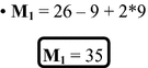
As an example, we will consider two wheelchairs (Instance I1 and Instance I2). Indeed these are manufactured with a mechatronic device to roll without help. The first chair Fig. 4. (Instance I1) comprises eight (8) components as illustrated in Fig. 5.

Wheelchair (Instance I1)

Wheelchair components
By applying the procedure proposed above to the instance I1 of Fig. 4, we will evaluate its modular. Thus for the chair we will take into account the components shown in Fig. 5.
If we consider the first instance I1 in Fig. 4 the matrix of the following transitive closure is obtained:

The related components of I1 are: {1}, {2}, {3.a}, {3.b}, {4}, {5}, {6}, {7}, {8}. Let’s not forget that for instance I1 component 3 (3. Arm + support) is multiplied by two (3.a, 3.b).
However, we will consider a second instance I2 having almost the same characteristics as the first but with a detail, the grouping of the component 3 of Fig. 5. (3. Arm + support) in one module. In this sense, we will act on the parameters of equation M to arrive at a more modular product.
After evaluation of the second, instance I2 in Fig. 6 we will have the following related components: {1}, {2}, {3}, {4}, {5}, {6}, {7}, {8} as shown in the following matrix

.

Wheelchair (Instance I2)
-
For instance, M1 we have:
-
For instance, M2 we have:
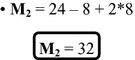


\( \varvec{M}_{2} < \varvec{M}_{1} \) so the solution I2 is more modular than \( \varvec{I}_{1} \)
Thus, we clearly see that Instance \( \left( {\varvec{I}_{2} ,\varvec{M}_{2} } \right) \) is more modular than Instance \( \left( {\varvec{I}_{1} ,\varvec{M}_{1} } \right) \), with fewer components because some are grouped into modules (3. Arm + support) and facilitate assembly and disassembly, hence the interest of maintainability.
7 Conclusions and Perspectives
The manufacture of innovative and modular products is a. good way to facilitate its maintainability, including the replacement of a defective part. Indeed, evaluating their behavior in the early stages of their design could help to improve the implementation of innovative products. Thus, these products will meet several requirements of the user before manufacture. This work will facilitate the use, maneuverability and especially the repair of future products. In our future work, we plan to carry out an ergonomic study of the products in order to alleviate the difficulty of use related to certain tools of work but also to solve the technical contradictions to get innovating products with respect to different behaviors.
References
Zanni-Merk, C., Cavallucci, D., Rousselot, F.: An ontological basis pour computer aided innovation. Comput. Ind. 60, 563–574 (2009). www.elsevier.com/locate/compind
Rousselot, F., Zanni-Merk, C., Cavallucci, D.: Towards a formal definition of contradiction in inventive design. Comput. Ind. 63, 231–242 (2012). www.elsevier.com/locate/compind
Sheu, D., Hou, C.T.: TRIZ-based trimming for process-machine improvements: slit-valve innovative redesign. Comput. Ind. Eng. 66, 555–566 (2013). www.elsevier.com/locate/caie
Wang, K., Nickerson, J.V.: A literature review on individual creativity support systems. Comput. Hum. Behav. 74, 139–151 (2017). www.elsevier.com/locate/comphumbeh
Menye, John the Baptist: Validation of maintainability and design availability of a multi-component system. Laval University (2009). http://www.exercicescorriges.com/i_107544.pdf
Diagne, S., Coulibaly, A., De Beuvron, F.: Towards a conceptual design for mechatronic product’s family development, pp. 94–99. IEEE (2014). https://doi.org/10.1109/idam.2014.6912677
Casner, D., Houssin, R., Knittel, D., Renaud, J.: An approach to design and optimization of mechatronic systems based on multidisciplinary optimization and based on the feedback of experiences. In: 21st French Mechanics Congress, 26–30 August 2013, Bordeaux, France (FR) (2013). http://documents.irevues.inist.fr/handle/2042/52520
Casner, D., Renaud, J., Knittel, D.: Design of mechatronic systems by topological optimization. In: 12th AIP-PRIMECA National Conference, AIP-Priméca (2011). https://hal.archives-ouvertes.fr/hal-00843025/
Coulibaly, A., De Beuvron, F.D.B., Renaud, J.: Maintainability assessment at early design internship using advanced CAD systems. In: Proceedings of IDMME-Virtual Concept, pp. 20–22 (2010)
Motte, D.: A review of fundamentals of systematic engineering design process models. In: International Design Conference - Design 2008, Dubrovnik, Croatia, 19–22 May 2008
Gausemeier, J., Mohringer, S.: Nes guideline VDI 2206 - a flexible procedure method for the design of mechatronic systems. In: Proceedings of the 14th International Conference on Engineering Design (ICED 2003), Stockholm (2003)
Ziemniak, P., Stania, M., Stetter, R.: Mechatronics engineering on the example of an innovative production vehicle. In: Proceedings of the 17th International Conference of Engineering Design (ICED 2009), 24–27 August 2009. Stanford University, Stanford (2009)
Rahman, R., Pulm, U., Stetter, R.: Systematic mechatronic design of a piezo-electric brake. In: Proceedings of the 16th International Conference of Engineering (ICED 2007), 28–31 August 2007. Design Society, Paris (2007)
Partto, M., Saariluoma, P.: Explaining failures in innovative throught processes in engineering design. Procedia - Soc. Behav. Sci. 41, 442–449 (2012)
Chandrasegaran, S.K., et al.: The evolution challenges and future knowledge representation in product design systems. Comput.-Aided Des. 45(2), 204–228 (2013)
Diagne, S., et al.: Towards a conceptual design for mechatronic products family development. In: 2014 International Conference on Innovative Design and Manufacturing, 13–15 August 2014, Montreal, Quebec, Canada (2014)
Diagne, S.: Conceptual semantic modeling for the behavioral performance engineering of complex products. University of Strasbourg, Graduate School of Mathematics Information and Engineering Sciences (MSII ED 269) UdS INSA Strasbourg Laboratory of Engineering Conception (LGeCo EA 3938). Doctor from the University of Strasbourg Discipline Engineering Sciences Specialty Computer Engineering Mechanical Engineering, July 2015
Baldwin, C., Clark, K.: Modularity in the design of complex engineering systems. In: Braha, D., Minai, A.A., Bar-Yam, Y. (eds.) Complex Engineered Systems, Science Meets Technology, pp. 175–205. Springer, Berlin (2006). https://doi.org/10.1007/3-540-32834-3_9
Homam_ISSA thesis dissertation: Contributions to the design of configurable products in advanced CAD systems, December 2015
Boothroyd, G., Dewhurst, P., Knight, W.: Product Design for Manufacture and Assembly. Marcel Dekker Inc., New York City (1994). ISBN 10: 0824791762, ISBN 13: 9780824791766
Author information
Authors and Affiliations
Corresponding author
Editor information
Editors and Affiliations
Rights and permissions
Copyright information
© 2018 IFIP International Federation for Information Processing
About this paper

Cite this paper
Aidara, C.A.T., Biaye, B.M., Diagne, S., Gaye, K., Coulibaly, A. (2018). Towards a Conceptual Design and Semantic Modeling Approach for Innovative Modular Products. In: Cavallucci, D., De Guio, R., Koziołek, S. (eds) Automated Invention for Smart Industries. TFC 2018. IFIP Advances in Information and Communication Technology, vol 541. Springer, Cham. https://doi.org/10.1007/978-3-030-02456-7_15
Download citation
DOI: https://doi.org/10.1007/978-3-030-02456-7_15
Published:
Publisher Name: Springer, Cham
Print ISBN: 978-3-030-02455-0
Online ISBN: 978-3-030-02456-7
eBook Packages: Computer ScienceComputer Science (R0)