
Abstract
Twin-Control (http://twincontrol.eu/) is a new concept for machine tool and machining process performance optimization. It is based on a new simulation model that integrates the different aspects that affect machine tool and machining performance. This holistic approach allows a better estimation of machining performance than single-featured simulation packages, including lifecycle concepts like energy consumption and end-of-life components. This theoretical representation of the machine is complemented with real process data by the monitoring of the most important variables of the machining process and machine condition. This monitored information, combined with the developed models, is used at machine level to perform model-based control actions and/or warn about damaged components of the machine tool. In addition, a fleet-level data management system is used for a proper health management and optimizes the maintenance actions on the machine tools.
You have full access to this open access chapter, Download chapter PDF
1 Introduction
Twin-Control (http://twincontrol.eu/) is a novel concept for machine tool and machining process performance optimization. It combines several features in the field of ICTs in manufacturing towards a better performance of machine tools [1]. A holistic simulation model, a so-called Digital Twin [2] of the machine tool, integrating most important features of machine tools and machining process, is combined with monitoring and data management capabilities.
Twin-Control will use a Digital Twin concept for the development of the simulation tool (Fig. 2.1). The Digital Twin is based on a combined application of the Cyber and Physical worlds, following the cyber-physical system (CPS) concept. The Cyber world consists in the computation, communication and control systems. The Physical world is composed by the natural and human-made systems governed by the laws of physics.

Twin-Control concept
A Digital Twin of the machine tool resulting from the combination of the different theoretical models that cover different aspects of the manufacturing process corresponds to the Cyber world, together with the cloud-based data management part, where machine fleet data is managed. The Physical world corresponds to the real machine that performs the real manufacturing process.
Both Physical and Cyber worlds will be interconnected. The Cyber world will make use of real machine tool and process data through all its life cycle. The Digital Twin of the manufacturing system has been created by combining the correspondent theoretical models according to machine tool design and process specifications. During part manufacturing, the holistic simulation model can be updated according to machine tool real condition using data obtained through monitoring and additional characterization tests designed for this purpose. This way, the virtual manufacturing system will be able to predict current machine/process performance in an accurate way.
In the same way, the simulation outputs obtained with the new Twin-Control tool will be useful through all machine tool life cycle. In the machine tool design stage, Twin-Control will be an extraordinary tool to predict the performance of projected machine tools. The same occurs with the process design, providing accurate estimation of cycle times and resultant part accuracy allowing a quick optimization procedure. By applying Twin-Control, machine tool and machining process set-up stage will be considerably reduced.
Finally, during machine tool usage period, process will be under control by the monitoring of the most important variables and the possibility to include simplified versions of the Digital Twin of the machine tool to perform model-based control actions [3]. According to machine tool health management, both local and fleet-level tasks will be implemented. On the one hand, variables like spindle temperature, power consumption and vibrations are monitored on machine level to control spindle’s condition. On the other hand, additional variables of the most important components of the machines will be also monitored and managed at fleet level.
The following pages provide an overview of the Twin-Control concept and its architecture and serve as introduction of the rest of the book, where developments are presented in detail. The first chapter introduces the Twin-Control concept. The second one presents an overview of the technical solution architecture of Twin-Control. Next, one of the highlights of the project, the industrial evaluation of Twin-Control is introduced. Finally, the conclusions are presented.
2 Twin-Control Architecture
Two separate application environments have been clearly defined: simulation, linked to a theoretical representation of the machine tool and the process; monitoring and control, linked to a real representation of the machine tool and the process. The fleet-based knowledge acts as a link between both representations by managing the real machine data (machine tool state, usage conditions, etc.) at a fleet level and using it to improve the accuracy of the simulation models. In the same way, simplified versions of the simulation part and results will be used in the real part to enhance monitoring and control activities (Fig. 2.2).

Main application environments of Twin-Control
The results of the project have been grouped using the same structure. This way, three main results have been obtained.
2.1 Integrated Simulation Tool
The application of complex theoretical models leads to very accurate estimations of process performance, allowing its optimization. A holistic simulation tool has been developed in the project to support machine tool and machining process design and optimization stages.
The core of the developed Digital Twin is a Virtual Machine Tool module based on SAMCEF Mecano [4] finite element (FE) software that is able to integrate the toolpath simulation and process effects (Fig. 2.3). This integration leads to a complete understanding of machine tool dynamic performance during real machining processes and will allow the prediction of the most important features like surface roughness and form errors. The integrated process models include features like cutting force estimation, stability analysis and even surface roughness estimation. The usage of ModuleWorks libraries provides advanced capabilities for tool-workpiece engagement calculation and also the possibility to visualize process results over workpiece geometry, improving user experience.

General overview of the simulation operation mode architecture
By using the results of this Virtual Machine Tool, some complementary features are studied through additional models. This way, energy efficiency of the simulated machine tool and/or process and end-of-life estimations of the most critical elements can be also provided by the developed Digital Twin.
End-of-Life module estimates the end-of-life of typically problematic machine tool components like bearings, linear guidelines and screw drivers. Based on the predictions of the integrated Virtual Machine Tool model, which will be able to estimate operating conditions of these elements, an accurate prediction of their end-of-life will be made based on the methods defined in the well-established standards defined by the International Standard Organization [5].
The energy efficiency module provides the energy consumption of machine tools. To gain a most wide transparency, the energy consumption is observed on a component level. This leads to the possibility to design energy efficient machine tools and processes. The Simscape model library to be developed will be the basis for the configurator. The physical input parameters are obtained from data sheets: if detailed characteristic curves are available, they are directly used for simulation; if less information is available, the behaviour will be modelled.
The link with the real world is obtained, in one direction, by the usage of the fleet-level knowledge stored in the cloud for validation (inputs and outputs for the simulations) and, in the other direction, by uploading simplified models or simulated results and parameters to the cloud (“reference” machine values).
By using the estimations provided by its different modules, Twin-Control will provide the chance to optimize the process by adapting the toolpath and/or cutting conditions. In addition, the analysis of the results provided by Twin-Control could be used to make changes at machine tool level. In addition, simplified versions of this Digital Twin will be integrated in the real world to improve machine tool and process performance.
Due to computational costs, this operation mode is oriented to offline simulations executed in a conventional PC. In the project, a simplified version based on the process models module has been also developed. This alternative version provides limited results, since does not include machine tool kinematics and dynamics, but allows faster configuration and simulation. Depending on the application, one of the two alternatives could be used.
2.2 Local Monitoring and Control System
The most important variables of the machine tool and machining process performance will be monitored and managed at machine and fleet level. For monitoring purposes, ARTIS Genior Modular is installed in the machines. This device allows direct exchange of CNC data at high real-time rate. Depending on the CNC model installed in the machine, CANOpen or Profibus communication protocol can be applied.
Additionally, an ARTIS OPR unit—Offline Process Recorder—will be used and connected via Ethernet to the Genior Modular to store the real-time data capturing and also to receive OPC data in non-real-time as a second data source. The OPR will act as a gateway by pushing real-time and OPC data to the remote or local service hosting the fleet-based database, in this case, KASEM® (Fig. 2.4).

Conceptual diagram of the monitoring architecture used in Twin-Control
The real-time local data management does not only monitor data, it allows implementing some intelligence that can be used to detect anomalous performance or even directly act on the machine controller to optimize its behaviour. For example, ARTIS process monitoring capabilities are used to safeguard production [6]. Spindle torque monitoring on all machines will be used to detect abnormal behaviour during processing. This could be a sudden action in case of tool breakage, delayed stop in the case of tool breakage during tapping operation or tool wear events. Currently, process monitoring is done based on a learning stage and, hence, can be only applied to medium-to-large batch sizes.
Within Twin-Control, the application of parts of the developed Digital Twin in the real world is proposed. The proposed monitoring hardware is the best environment to do this integration. For example, the integration of process models with real monitored data could be used for process monitoring [3], replacing the learning stage when it is not feasible, for example, in aerospace applications where batches are normally small.
A new energy monitoring system that avoids the extensive use of hardware (hall) sensors has been also implemented, leading to a drastic reduction in investment costs for an energy monitoring solution on component level. Using CNC and PLC data, the module will be able to determine energy consumption per component.
Other similar features like the integration of CNC simulation capabilities have been developed in the project and will be covered in specific chapters of this book.
The different features are visualized in a central HMI solution (Fig. 2.5). HMI will be enhanced by including PlugIns of additional features like fleet-level knowledge reports or graphical representation of simulation results. This machine tool control-based HMI could be also made available on a tablet, external PC, or smartphone, since Genior HMI product is available as Windows DLL. This way, operators that are not in front of the machines can receive information, including alarm signals.

Conceptual design of the ARTIS HMI including Twin-Control PlugIns
2.3 Fleet-Based Knowledge System
From Twin-Control point of view, fleet refers to a set of machine tools of different owners and builders. In addition to individual modelling and health monitoring, it is necessary to provide fleet-wide facilities. Towards this end, the platform integrates semantic modelling that allows gathering and sharing data, models and expertise from the different systems and equipments, using a fleet-wide approach. The fleet-based data management, depicted in Fig. 2.6, is built around a global methodology that allows guiding the proactive strategy definition all along the asset life cycle. It provides a consistent framework that enables coupling data and models to support diagnostics, prognostics and expertise through a global and structured view of the system and enhances understanding of abnormal situation (i.e. system health monitoring level).

Hierarchical approach of the proactive fleet management [7]
Starting from the definition of the system functioning in relation to its environment, the formalization of the system malfunctioning analysis is then considered. The corresponding knowledge (i.e. functioning and malfunctioning models) is incrementally built within a knowledge-based system that supports a structured and hierarchical description of the fleet. This formalization enables to reduce the effort for data consolidation within system health management as well as for knowledge aggregation within fleet health management, since it enhances understanding of the impacts between and within levels.
The fleet-level data management platform proposed for the Twin-Control project is based on KASEM® (Knowledge and Advanced Service for E-Maintenance) [8]. It is a collaborative e-maintenance platform, integrating engineering, proactive maintenance, decision-making and expertise tools [9] and used in former Power-OM project [10].
2.3.1 Data Exchanges with Machine Tools
Twin-Control’s fleet platform is in the “cloud”, i.e. on the Internet, and hosted to a predict secure server. Machine tools push data to the server to feed the knowledge base. Details of the proposed monitoring and data management architecture are presented in Sect. 3.1 of this book.
The concept of fleet data management is presented in Fig. 2.7. The different machines are monitored using the correspondent. A detailed architecture for each of the use cases of the project will be presented in Sect. 3.1.

Fleet data management approach used in Twin-Control
Figure 2.8 summarizes presents the architecture proposed for Twin-Control fleet data management. All collected, computed and extracted information by the platform will be stored in the knowledge base. For each machine tool, expected inputs of the fleet platform can be classified in two groups:

Architecture of Twin-Control fleet data management
-
Automatic inputs that are regularly pushed to the fleet platform. The automatic inputs are:
-
Collected data: raw data acquired directly from the machine tools with high and low sampling rate according to data dynamics.
-
Local processing information: locally computed information (in ARTIS), such as energy monitoring information.
-
Alarms: warnings generated by both CNC of the machines tools and monitoring hardware.
-
-
Manual inputs that are entered or uploaded by users. The manual inputs are:
-
Characterization tests: test results file and/or additional collected data from mobile equipment can be uploaded on the platform via a specific HMI represented by the bloc “Data importation”.
-
Machine references: To detect behavioural drifts, it is necessary to have reference behaviours, the fleet platform can learn references but also to use references extracted from the simulation environment.
-
Fleet platform will be powered by the KASEM® platform of predict. KASEM® will also provide generic and standard HMI that could be updated to fit project requirements. KASEM® is a Web platform with a service-oriented architecture (SOA). Following sub-sections explain main functions deployed in the fleet platform once machine tools knowledge will be formalized.
2.3.2 Health Assessment
Health assessment functionality consists of the correlation of various information computed by the fleet platform to evaluate the health status of one machine and health status of machines set. Health assessment is mainly based on a rating principle of different features:
-
Key performance indicators (KPIs): These indicators allow users to have a synthetic view of an equipment, a machine or a fleet of machines. They are computed at the equipment, and then they are aggregated to build higher-level indicators. Aggregation of equipment KPI gives machine KPI, and aggregation of machine KPI gives the fleet KPI.
-
Drift detection: this functionality is necessary to have early detections of machine non-nominal behaviours. Early detection is based on residual analysis of the difference between observed behaviour and reference behaviour. Early detection allows generating proactive alerts to anticipate fault occurrences and then to avoid machine tool down-time. Detection can be done on operating points but also on transient behaviours. Figure 2.9 depicts an early detection of a temperature transient drift according to spindle speed level. In this case, detection is based on a thermal model learned by the fleet platform.
Fig. 2.9 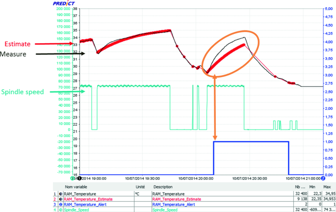
Example of drift detection on temperature measurement
-
Machine references: To detect behaviour drifts, it is necessary to have some reference behaviours. The fleet platform can learn references from the monitored data, but can also use simulation models to create these references. In this line, the fleet platform will take advantage of the simulation models developed within Twin-Control project.
-
Machine tool characterization tests: The periodic execution of the test procedure will allow obtaining a good source of information that reflects the condition of the different components of the machine tool without process effects.

A score is assigned to each component of the health status, and then scores are merged to compute the health status. This principle allows a graphical representation of machine’s health status on radar plot. Several machines can be overlaid to make a fleet comparison as depicted in Fig. 2.10.

Graphical representation of machine health status in KASEM®
2.3.3 Event’s Sequence Analysis
Events include both alarms from local monitoring and alerts from fleet drift detection. This module will oversee the interpretation of event sequences, i.e. the interpretation of frequency and order of the events. Information about event types and the time stamps of their occurrence will be used to analyse the time series data and thus finding dependencies between different alarms. Generic causal models, i.e. models shared by all machines of the fleet, will be used during the analysis. A causal model represents the relationship between the different event types. These causal relationships can be used to recognize an event sequence on a given period. Once the sequence is identified, causal models allow to identify the sequence root cause (diagnosis) but also to know what could be the next event (prognostic) of the sequence.
This module will use event sequences as signatures of machine situations. For each machine, past situations will be stored in the knowledge base with generic label to build the fleet experience feedback and thus to improve event’s sequence analysis.
2.3.4 Platform Portal and Outputs
For accessibility, all the functions of the platform are available through a Web portal. Results can also be made available directly on site by means of report, for instance, that can be sent (e.g. by mail) to the users and/or displayed on machine local HMI through ARTIS PlugIn. The platform Web portal will provide HMI to support decision-making for diagnosis activities, to visualize knowledge-based information with dynamics dashboards and static reports.
In addition, a functionality of data and knowledge extraction will be developed for both manually and automatically download information from platform to simulation environment and local monitoring environment.
3 Twin-Control Validation and Evaluation
The different Twin-Control features have been tested, first, at laboratory level, allowing a proper tuning, when needed, and validating their functionalities. Apart from that, one of the highlights of the project has been the evaluation of Twin-Control in industrial environment.
Different demonstrator scenarios have been implemented in two of the key industries for European economy: automotive and aerospace. These two sectors are very dependent on machine tool industry but show several differences with respect to the process types and requirements. Automotive sector typically deals with large batches of moderate cycle-time parts. Current major concerns are (1) to ensure part quality over time, (2) reduction of breakdowns and (3) energy efficiency. In aerospace, smaller batches are usually manufactured, but parts are normally bigger and with a complex geometry. There, new process set-up times and quality requirements are most important concerns.
The different requirements of such important industries have been taken as a reference to determine the Twin-Control concept and architecture. Apart from that, both use cases will be used for the evaluation of the different features of Twin-Control, not only at technical level, but also by studying the impact caused by the features in the end-users. For each automotive and aerospace sector, a tandem of end-users composed by a part manufacturer and one of its machine tool providers will be involved in this industrial validation (Fig. 2.11). Three machines will be monitored on each end-user installation to apply fleet-based knowledge management.

Industrial validation and demonstration in two industries: aerospace and automotive
-
For aerospace, Twin-Control will be implemented in several Gepro system machines in MASA Aerospace installations, in Logroño (Spain). Gepro system develops big-sized gantry type multi-spindle machine tools with which MASA aerospace machines medium-to-big size aircraft parts.
-
For automotive, Twin-Control will be implemented in several COMAU machine tools located in Renault plant at Cleon (France). In the manufacturing line selected for the automotive demonstration scenario, COMAU machine tools (medium-sized high-speed machining centres) are applied by Renault to machine housings of gearboxes.
The three main results of the project, presented in this chapter, have been evaluated in both validation scenarios, following a specific approach defined for Twin-Control project. Different Scenarios of Use have been defined by end-users, and the different functionalities that affect each scenario are independently evaluated. For each scenario, key performance indicators (KPIs) are defined to evaluate the impact of each Twin-Control feature implementation. The proposed scenarios are:
-
Scenario of Use 1: Machine tool design. The simulation capabilities developed in Twin-Control can improve the product development process of machine tool builders.
-
Scenario of Use 2: Machining process design. Twin-Control process simulation feature provides the chance to optimize process definitions of part manufacturers at design stage and, hence, minimize set-up times and reduce scrap parts in this process.
-
Scenario of Use 3: Process control. Suited for operator level in part manufacturer’s workshop, the Twin-Control monitoring and control device enhanced by embedded simulation models allow a better control of the manufacturing process.
-
Scenario of Use 4: Maintenance. Fleet knowledge system developed in Twin-Control will lead to a better maintenance strategy for end-users.
-
Scenario of Use 5: Quality. The combination of process and quality monitoring leads to a better control of part quality by reducing the amount of time spent in measurements.
Apart from that, three additional use cases have been defined this time for dissemination purposes. Twin-Control has been implemented in three pilot lines at reference-manufacturing research locations: The Advance Manufacturing Research Centre with Boing (AMRC) at Sheffield, United Kingdom, The Eta-Factory at Darmstadt, Germany, and the CFAA at Bilbao, Spain. Twin-Control can be presented to industrial partners in these relevant environments. Indeed, during the project, workshops have been organized at each pilot line (Fig. 2.12).

Twin-Control dissemination activities in relevant pilot lines: a Johannes Sossenhiemer (Technical University of Darmstadt) presents Twin-Control features linked with energy efficiency at the ETA-Factory (Darmstadt, Germany). b Luke Berglind (University of Sheffield) presents a demonstration of the integration of process models with monitored data at the Advanced Manufacturing Research Centre with Boing (Sheffield, UK)
4 Conclusions
Twin-Control (http://twincontrol.eu/) is a new concept for machining process performance optimization, covering ICT-related features like Digital Twin, condition monitoring, fleet data management and model-based control. This section presents the concept behind Twin-Control and the proposed architecture, defined after gathering requirements from end-users involved in the project. In addition, the industrial evaluation approach is also introduced. In the next chapters of the book, the presented features will be defined in detail.
References
Kagermann, H., Wahlster, W.: Recommendations for implementing the strategic initiative INDUSTRIE 4.0. Final report of the Industrie 4.0 Working Group
Boschert, S., Rosen, R.: Digital twin—the simulation aspect. In: Hehenberger, P., Bradley, D. (eds.) Mechatronic Futures. Springer, Cham (2016)
Denkena, B., Fischer, R., Euhus, D., Neff, T.: Simulation based process monitoring for single item production without machine external sensors. In: 2nd International Conference on System-Integrated Intelligence: Challenges for Product and Production Engineering. Procedia Technology, vol. 15, pp. 341–348 (2014)
Maj, R., Bianchi, G.: Machine tools mechatronic analysis. In: Proceedings of the Institution of Mechanical Engineers Part B Journal of Engineering Manufacture 220 (2016)
ISO 281:2007: Rolling Bearings—Dynamic Load Ratings and Rating Life
http://www.artis.de/en/technology/products/process-monitoring/
Monnin, M., Leger, J-B., Morel, D.: Proactive facility fleet/plant monitoring and management. In: Proceedings of 24th International Congress on Condition Monitoring and Diagnostics Engineering Management, 29th May–1st June, Stavanger, Norway (2011)
Léger, J-B.: A case study of remote diagnosis and emaintenance information system. Keynote speech of IMS’2004. In: International Conference on Intelligent Maintenance Systems, Arles, France (2004)
Prado, A., Alzaga, A., Konde, E., Medina-Oliva, G., Monnin, M., Johansson, C-A., Galar, D., Euhus, D., Burrows, M., Yurre, C.: Health and performances machine tool monitoring architecture. E-maintenance Conference from 17th to 18th of June 2014, Luleå, Sweden
Author information
Authors and Affiliations
Corresponding author
Editor information
Editors and Affiliations
Rights and permissions
Open Access This chapter is licensed under the terms of the Creative Commons Attribution 4.0 International License (http://creativecommons.org/licenses/by/4.0/), which permits use, sharing, adaptation, distribution and reproduction in any medium or format, as long as you give appropriate credit to the original author(s) and the source, provide a link to the Creative Commons license and indicate if changes were made.
The images or other third party material in this chapter are included in the chapter's Creative Commons license, unless indicated otherwise in a credit line to the material. If material is not included in the chapter's Creative Commons license and your intended use is not permitted by statutory regulation or exceeds the permitted use, you will need to obtain permission directly from the copyright holder.
Copyright information
© 2019 The Author(s)
About this chapter

Cite this chapter
Armendia, M., Alzaga, A., Peysson, F., Euhus, D. (2019). Twin-Control Approach. In: Armendia, M., Ghassempouri, M., Ozturk, E., Peysson, F. (eds) Twin-Control. Springer, Cham. https://doi.org/10.1007/978-3-030-02203-7_2
Download citation
DOI: https://doi.org/10.1007/978-3-030-02203-7_2
Published:
Publisher Name: Springer, Cham
Print ISBN: 978-3-030-02202-0
Online ISBN: 978-3-030-02203-7
eBook Packages: EngineeringEngineering (R0)