
Abstract
Suppose we progressively increase the velocity of fluid which is flowing upward through a batch of solids. The frictional resistance increases, and eventually a point is reached where the resistance just equals the weight of solids. At this point the solids become suspended—in other words, they
become “fluidized”—and the superficial velocity of fluid needed to just fluidize the solids is called the minimum fluidizing velocity u mf . As the flow rate of fluid is increased beyond this point, a liquid fluidized bed keeps expanding, while a gas bed expands only slightly. This progression is shown in Fig. 7.1. The fluidized state has many desirable liquid-like properties. For example, we can easily move solids about just by pumping or by gravity flow.
Keywords
These keywords were added by machine and not by the authors. This process is experimental and the keywords may be updated as the learning algorithm improves.
1 The Fluidized State
Suppose we progressively increase the velocity of fluid which is flowing upward through a batch of solids. The frictional resistance increases, and eventually a point is reached where the resistance just equals the weight of solids. At this point the solids become suspended—in other words, they
become “fluidized”—and the superficial velocity of fluid needed to just fluidize the solids is called the minimum fluidizing velocity u mf . As the flow rate of fluid is increased beyond this point, a liquid fluidized bed keeps expanding, while a gas bed expands only slightly. This progression is shown in Fig. 7.1. The fluidized state has many desirable liquid-like properties. For example, we can easily move solids about just by pumping or by gravity flow.

Transition from a packed to a fluidized bed as the velocity of upflowing fluid is raised. Note that the volume of solids in the vessel is
The progression from packed bed to fluidized bed is best followed on a pressure drop versus velocity graph, as shown in Figs. 7.2 and 7.3. The packed bed behavior, shown on the left of these figures, is reasonably represented by the Ergun equation (6.9)

Frictional loss in the packed and in the fluidized state

The pressure drop vs. velocity curve in more detail and on log–log coordinates
where the characteristic particle size d p is given by equations (6.3), (6.4), (6.5), (6.6), and (6.7). From this equation we see that
Point A in Figs. 7.2 and 7.3 represents the just fluidized bed; thus, it is at the minimum fluidizing velocity. To the right of point A, the bed is well fluidized. In the following sections we will find
2 Frictional Loss and Pumping Requirement Needed to Fluidize a Bed of Solids
Consider the setup of Fig. 7.4. Solids will just fluidize (u 0 = u mf , ε = ε mf ) when

Fluidized bed of solids
or
or, in symbols,
Writing the mechanical energy balance of equation (6.12) between points 1 and 2 of Fig. 7.4 and ignoring kinetic energy effects and the resistance of the distributor give for unit cross-sectional area of bed

The pumping requirement is found by writing the mechanical energy balance between points 0 and 2. This gives
Equations (1.9), (1.10), (1.11), (1.12), (1.13), and (1.14) deal further with pumping requirements.
In more realistic situations the frictional loss of the air distribution plate holding up the solids, the cyclone separator or bag filters above the bed, and the other equipment in the line between points 1 and 2 must be accounted for. Thus, in place of equation (7.3), we should more properly write
At flow velocities higher than u mf , the frictional loss per unit of fluid passing through the bed remains practically unchanged, as shown in Fig. 7.2 or 7.3; however, the pumping power needed will change in proportion to the fluidizing velocity u 0 .
3 Minimum Fluidizing Velocity, u mf
The intersection of equations (7.1) and (7.2) represents the condition where the solids just fluidize (point A of Fig. 7.2). So combining these two equations gives the following expression for finding the minimum fluidizing velocity:

In the special case of very small or very large particles, the above expression simplifies as follows: for very small particles
and for very large particles
If ε mf and/or sphericity \( \phi \) (which enters in d p ) is not known, we can use the observation of Wen and Yu (1966) that 1/ϕε 3 mf and (1 − ε mf )/ϕ 2 ε 3 mf are both close to constant for all systems. Chitester et al. (1984) summarized the reported studies and recommended using
Replacing these expressions in equation (7.4) and combining with equation (6.3) then give
For more on the flow characteristics of fluidized beds, see Kunii and Levenspiel (1991).
Example 7.1. Power to Run a Fluidized Incinerator for Municipal Garbage
Room temperature air (20 °C) is to be compressed and fed to a fluidized incinerator which operates at high temperature and uses sand as a carrier solid. Find the power requirement of the compressor if the unit is to operate at ten times the minimum fluidizing velocity.
Data:
-
Incinerator: 3-m-i.d., slumped bed height = 0.56 m
-
Solids: −28 + 35 mesh sand, ρ s = 2,500 kg/m3, \( \phi \) = 0.875.
-
Temperature of the bed = 850 °C. Because of its remarkably good heat distribution characteristics, a well-fluidized bed is close to uniform in temperature, so assume that the air reaches 850 °C as soon as it enters the bed.
-
Take μ air, 850 °C = 4.5 × 10⁻⁵ kg/m s.
-
Efficiency of the compressor and motor = 70 %.
-
Ignore the pressure drop of the distributor and of the cyclones.

Solution
Our strategy will be to determine, in turn, the pressure drop through the bed, the gas velocity through the bed, and finally, the power requirement. But let us first evaluate a few needed quantities.
Calculate Δp fr from equation (7.2)
and
Calculate u mf from equation (7.1)
Replacing known values gives
or
and solving gives
Hence, the velocity of gas entering the bed at 850 °C and 110 kPa is
Note 1: Instead of finding Δp fr and the u mf , we could have found u mf directly from equation (7.4). It will give the same answer.
Note 2: At the start we could have guessed that this was a fine particle system, in which case equation (i) becomes
A check of the Reynolds number then shows that Re p,mf < 20, which satisfies our original guess.
Note 3: If we were not given \( \phi \) and/or ε mf , we would have to use equation (7.7) to evaluate u mf . This gives
from which
Calculate the power requirement from equations (1.12) and (1.14) but first determine the molar flow rate of gas from the conditions of the gas just entering the bed. Thus,
and now an energy balance about the compressor gives
\( \begin{array}{c}-{\dot{W}}_s=\frac{k}{k-1}\cdot \frac{\dot{n}R{T}_1}{\eta}\left[{\left(\frac{p_2}{p_1}\right)}^{\left(k-1\right)/k}-1\right]\\ {}=\frac{1.4}{1.4-1}\frac{(88.5)(8.314)(293)}{0.7}\left[{\left(\frac{110,\kern-0.75pt 106}{101,\kern-0.25pt 325}\right)}^{\left(1.4-1\right)/1.4}-1\right]\\ {}=\kern0.5em 25,\kern-1pt 902\kern0.5em \mathrm{J}/\mathrm{s}=26\kern0.5em \mathrm{kW},\ \mathrm{to}\ \mathrm{gas}\end{array} \)
Problems on Fluidized Beds
-
7.1. Air at 20 °C passes upward through a bed (2 m high, 0.5 m i.d., ε m = 0.4, ε mf = 0.44) of limestone (d p = 2 mm, ρ s = 2,900 kg/m3). What inlet air pressure is needed to fluidize the solids (outlet pressure = 1 atm)?
-
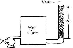
7.2. Air at 1.1 atm and 20 °C filters upward through a 10-m high bed of 1-mm solid silver spheres (ε mf = 0.4) and discharges to the atmosphere. Ten meters!! What a waste! Silver is valuable, so let’s sell some of it. No one will know as long as the remaining solids remain as a fixed bed. What height of silver should we leave behind so that the bed won’t fluidize?
-
7.3. We plan to pass air upward through a bed of solids resting on a screen. Will the solids fluidize?
-
Data:
-
$$ \begin{array}{c}\mathrm{Solids}:\ {\rho}_{\mathrm{s}} = 3,\kern-1pt 000\ \mathrm{kg}/{\mathrm{m}}^3,\ {d}_p = 2\ \mathrm{m}\mathrm{m},\ {\varepsilon}_m = 0.36\\ {}\mathrm{Bed}:\ 2\ \mathrm{m}\ \mathrm{high},\ 0.5\ \mathrm{m}\ \mathrm{i}.\mathrm{d}.\\ {}\mathrm{Air}:\ {p}_{\mathrm{inlet}} = 130\ \mathrm{kPa},\ {p}_{\mathrm{outlet}} = 100\ \mathrm{kPa},\ T = 100\kern0.3em {}^{\circ}\mathrm{C}\end{array} $$
-
7.4. Air at 150 kPa and 20 °C will flow upward at a superficial velocity of 1 m/s through a bed of solids.
-
(a) Will the solids fluidize?
-
(b) Find the outlet air pressure for this flow rate.
-
-
Data:
-
$$ \begin{array}{c}\mathrm{Solids}:\ {\rho}_{\mathrm{s}} = 4,\kern-1pt 500\ \mathrm{kg}/{\mathrm{m}}^3,\ {d}_p = 1\ \mathrm{m}\mathrm{m}\\ {}\mathrm{Bed}:\ {\varepsilon}_m = 0.36,1\ \mathrm{m}\ \mathrm{high},\ 0.3\ \mathrm{m}\ \mathrm{i}.\mathrm{d}.\end{array} $$
-
7.5. Air enters (u 0 = 1 m/s, p = 0.2 MPa, T = 293 K) and passes upward through a bed of packed solid (d p = 1 mm, ε m = 0.4, ρ s = 9,500 kg/m3, L m = 1 m) sandwiched and kept in place between two screens having negligible resistance to airflow.
-
(a) What is the outlet pressure?
-
(b) The upper screen is removed. Now what is the outlet pressure?
-
-
7.6. Air at about 20 °C and 1 atm passes upward through a fixed bed of solids.
-
(a) At what superficial air velocity will the particles just fluidize?
-
(b)At minimum fluidizing velocity what will be the pressure drop across the bed?
-
-
Data:
-
$$ \begin{array}{c}\mathrm{Solids}:\ {d}_{\mathrm{s}\mathrm{ph}} = 15\ \mathrm{m}\mathrm{m},\ \phi = 0.67,\ {\rho}_{\mathrm{s}} = 3,\kern-1pt 000\ \mathrm{kg}/{\mathrm{m}}^3\\ {}\mathrm{Bed}:\ {\varepsilon}_m = {\varepsilon}_{mf} = 0.4,\ \mathrm{height} = 0.5\ \mathrm{m},\ \mathrm{diameter} = 0.1\ \mathrm{m}\end{array} $$
-
7.7. Calculate u mf for a bed of irregular particles (take d p = d scr · \( \phi \) s ) fluidized by air at about 20 °C and 1 atm.
-
Data:
-
$$ \begin{array}{c}\mathrm{Solids}:\ {\mathrm{d}}_{\mathrm{scr}} = 100\ \mu \mathrm{m},\kern0.5em {\phi}_s = 0.63,\kern0.5em {\rho}_s = 5,\kern-1pt 000\ \mathrm{kg}/{\mathrm{m}}^3\\ {}\mathrm{Bed}\ \mathrm{voidage}:\ {\varepsilon}_m = {\varepsilon}_{mf} = 0.6\ \left(\mathrm{estimated}\right)\end{array} $$
-
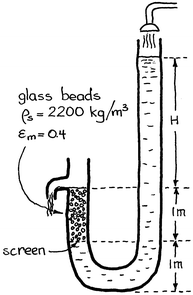
7.8. Water flows through a U-tube that has a section packed with 1-mm glass beads (ρ s = 2,200 kg/m3, ε m = 0.40) as shown below on the left. As the upper water level is changed so does the flow rate in the packed bed.
-
(a)At what height H will the spheres in this problem just lift up and wash away?
-
(b) What is the velocity of the water when this occurs?
-
-
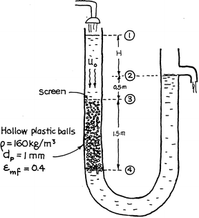
7.9.A packed bed flow experiment is sketched below on the right. As the water flow rate is increased, the water level at point 1 rises and H increases. Eventually, a point is reached when the plastic balls just fluidize downward. Determine the height H and the liquid flow rate when this should occur.
-
7.10. Here is a proposed ride for the Tokyo Disneyland. Crowd a group of 75 children into a Plexiglas cylinder 3 m i.d. and fluidize them. Hands and feet flying, what fun it would be. And we’d call it “Typhoon”, the Chinese word for “big wind.”
-
(a) What air velocity would be needed to just fluidize the children?
-
(b) What size of compressor at 50 % efficiency (to account for inefficiencies, distributor resistance, screen above the bed to catch the occasional blown-out child) is needed if u 0 = 1.1 u mf ?
-
-
Data: Children weigh from 25 to 50 kg with 40 kg as a mean. For suitably dressed screaming children (crash helmets, padding, and all) \( \phi \) = 0.22, ρ = 800 kg/m3, and I suppose that ε m ≅ 0.4, ε mf = ε f = 0.5 are fair estimates of the void fraction between children.
-
7.11. Example 7.1 made the simplifying assumption that the pressure drop of the distributor plate and of the cyclone are relatively small and can be ignored. Relax this assumption and repeat Example 7.1 with the more realistic assumption that Δ p distributor = 20 % Δ p bed and Δ p cyclones = 10 % Δ p bed.
-
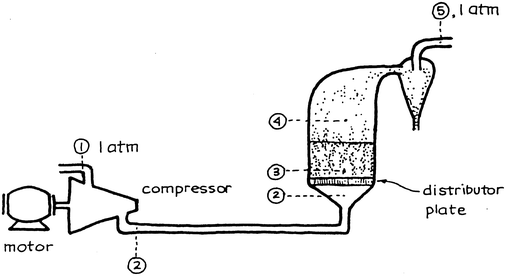
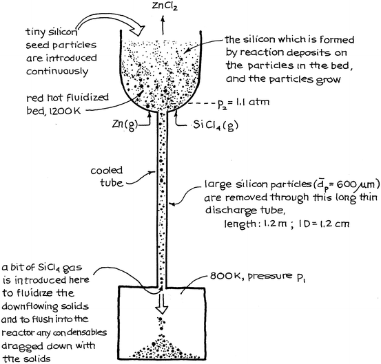
7.12.Production of ultrapure silicon. Battelle Memorial Institute is developing a fluidized bed process for producing ultrapure solar cell grade silicon. The reaction is to proceed at 1,200 K as follows:
-
$$ 2\mathrm{Z}\mathrm{n}\left(\mathrm{g}\right) + {\mathrm{SiCl}}_4\left(\mathrm{g}\right)\to\ 2{\mathrm{ZnCl}}_2\left(\mathrm{g}\right) + \mathrm{S}\mathrm{i}\downarrow $$
-
and the process looks somewhat as shown on the following page. If the discharge tube plugs up, the process is ruined. To avoid this plugging, sticking, or bridging of solids, we pass a bit of SiCl4 gas up the tube to fluidize the solids. This will insure smooth downflow of solids.
-
(a) How would you be able to tell whether the solids in the discharge tube are fluidized or not?
-
(b) What gas flow up the tube would you need to keep the downflowing solids fluidized?
-
-
Data: Silicon particles in discharge tube:
-
$$ {d}_p=600\kern0.5em \mu \operatorname{m},\kern0.5em {\rho}_s=2,\kern-1pt 200\kern0.5em \mathrm{kg}/{\mathrm{m}}^3,\kern0.5em {\varepsilon}_{mf}=0.4 $$
-
SiCl4 gas at average conditions (1,000 K) in the discharge tube:
-
$$ (mw)=0.170\kern0.5em \mathrm{kg}/\mathrm{m}\mathrm{ol},\kern0.5em \mu =4\times {10}^{-5}\mathrm{kg}/\mathrm{m}\kern0.5em \mathrm{s} $$
-
7.13.Cold model of an FBC (fluidized bed combustor). Our laboratory has a cold model of a tube-filled fluidized furnace for the generation of steam from the combustion of coal. The unit consists of a vessel 1 m2 in cross section, which fluidizes crushed rock, roughly 4 mesh in size, with a settled bed height of 0.5 m. Room temperature air (20 °C) enters the compressor, but it is estimated that the bed itself will be hotter, roughly 40 °C.
-
(a) Find the superficial gas velocity which will just fluidize the solids.
-
(b) We plan to operate the bed at four times the minimum fluidizing velocity. What size of pump–motor setup at 60 % overall efficiency will be needed? Assume that the pressure drop through the distributor plate and the cyclone will be 20 % and 10 % of the bed, respectively.
-
-
Data:
$$ \begin{array}{l}{\rho}_{\mathrm{s}} = 2,\kern-1.25pt 900\ \mathrm{kg}/{\mathrm{m}}^3,\ {d}_{\mathrm{s}\mathrm{cr}} = 5\ \mathrm{mm},\ \phi = 0.6\\ {}{\varepsilon}_m = 0.4,\ {\varepsilon}_{mf} = 0.5,\ {\varepsilon}_f = 0.6\\ {}{\mu}_{\mathrm{air}}\left(40\ {}^{\circ}\mathrm{C}\right) = 1.96 \times {10}^{\hbox{--} 5}\ \mathrm{kg}/\mathrm{m}\ \mathrm{s}\end{array} $$ -
7.14. Repeat the previous problem with one change: instead of using these large particles, use roughly 28 mesh solids (d scr = 0.5 mm).
-
7.15. Our university laboratory has a large fluidized test unit 1 m × 1 m in cross section and 7 m high. In this unit we plan to fluidize limestone (ρ s = 2,930 kg/m3, d p = 0.65 mm, ε bed = 0.5) at 1.5 u mf . The fluidizing air comes from a compressor which delivers just about any flow rate but with a maximum outlet pressure of 122 kPa. What height of solids can we fluidize with this unit?
-
Data: Room air is at 20 °C and the pressure here in Corvallis is about 100 kPa.


References
D.C. Chitester et al., Characteristics of fluidization at high pressure. Chem. Eng. Sci. 39(253) (1984)
D. Kunii, O. Levenspiel, Fluidization Engineering, 2nd edn, Chap. 3, (Butterworth, Boston, 1991)
C.Y. Wen, Y.H. Yu, A generalized method for predicting the minimum fluidization velocity. AIChE J. 12(610) (1966)
Author information
Authors and Affiliations
Rights and permissions
Copyright information
© 2014 Springer Science+Business Media New York
About this chapter
Cite this chapter
Levenspiel, O. (2014). Flow in Fluidized Beds. In: Engineering Flow and Heat Exchange. Springer, Boston, MA. https://doi.org/10.1007/978-1-4899-7454-9_7
Download citation
DOI: https://doi.org/10.1007/978-1-4899-7454-9_7
Published:
Publisher Name: Springer, Boston, MA
Print ISBN: 978-1-4899-7453-2
Online ISBN: 978-1-4899-7454-9
eBook Packages: Chemistry and Materials ScienceChemistry and Material Science (R0)