
Abstract
The current chapter presents a set of main aspects of timber building with a focus on timber-frame constructions. A brief description of timber’s material characteristics in Sect. 3.1 aims at getting acquainted with potential advantages and disadvantages of planning and designing timber buildings, in comparison with using other structural materials, such as concrete or masonry. Section 3.2 discusses predominantly used structural systems of timber construction along with the most important structural and technological characteristics and possibilities. Section 3.3 describes computational models and methods, with their limitations and application in practice. The influence of the sheathing material and the openings studied in our previous numerical and experimental research is additionally shortly presented in order to provide a better insight into a rather problematic area of applying the glazing to timber buildings, which is the main contents part of Chap. 4. Multi-storey prefabricated timber building is one of the increasing opportunities for the public, commercial and residential sectors in the future. Stability problems appearing due to heavy horizontal actions along with possible strengthening solutions already applied in practice are the topic of Sect. 3.4.
Keywords
These keywords were added by machine and not by the authors. This process is experimental and the keywords may be updated as the learning algorithm improves.
3.1 Timber as a Building Material
Timber is a live organisms’ product and thus a natural material exposed to parasites and bacteria. Alternate exposure to humidity makes timber unsustainable while its organic structure accounts for its inhomogeneity, which is a rather negative construction-related feature. Another specific area is timber’s fire resistance, a highly specific problem to which a more detailed approach follows further in this chapter. The three characteristics mentioned above are said to be the main drawbacks of using timber in construction. However, the listed disadvantages can be partially or even fully overcome with appropriate use of timber, which will be further discussed in Sects. 3.1.1, 3.1.2 and 3.1.3.
Timber has, on the other hand, excellent construction features. Its compressive strength is almost equal to that of concrete but its tensile strength is significantly higher. The most important advantage over concrete is its much lower weight. Moreover, if the weight of both materials is equivalent, timber satisfies almost the same construction requirements as steel. Nevertheless, on account of its relatively low value of the modulus of elasticity, which is approximately three times lower than that of concrete and twenty times lower than that of steel, timber is not suitable for structures with extreme spans or heights although it has become an ever more frequent material used in multi-storey prefabricated construction, which is a topic treated in Sect. 3.4.
Timber is, in addition, a non-demanding material for prefabrication due to its organic structure and low density. It is also an ideal construction material from the viewpoint of energy efficiency since CO2 emissions in production of a timber element tend to be approximately two times lower than that those present in manufacturing an equivalent brick element, three times lower than in the case of a concrete element and six times lower than CO2 emissions in steel element production. The reason lies in photosynthesis enabling a growing tree to store CO2 which is then released only in the burning process of the timber mass. Since the above-described characteristics of timber frequently reoccur in Chap. 4, the following subsections aim at their more specific presentation.
3.1.1 Inhomogeneity of Timber
Timber is an organic substance, inhomogeneous in the organic, anatomical and physical sense. Most of its physical and mechanical properties differ depending on the grain direction, which is seen in the pronounced anisotropy. Timber’s properties are generally best in the direction parallel to the grain, with their intensity decreasing proportionally to the deviation from the longitudinal axis, reaching bottom qualities perpendicularly to the grain. These are typical features distinguishing timber from other construction materials.
A detailed analysis of wood structure needs to be preceded by a definition of a set of terms to be used in our further discussion. In contrast to some tropical and subtropical trees (palm tree, bamboo), European trees’ growth is characterized by a simultaneous increase in the tree height and width, with the height growth being typical of the juvenile phase followed by the diameter growth in the full vigour phase. The latter results in cylinder-shaped growth layers called annual rings. Clearly visible boundaries between the layers are called annual ring boundaries. They appear as concentric circles arranged around the stem core called the pith in the cross section and look like axial, almost parallel lines (Fig. 3.1) in the radial section. Annual ring boundaries typically have a more distinctive definition in conifers than in deciduous trees. The width between annual ring boundaries is referred to as annual ring width.

Cross section of the wood element
As seen in the cross section, annual ring width becomes larger every year which is seen in progressive distribution of the annual rings ranging from the narrowest ones around the pith where timber is the oldest and most compressed to the widest annual rings on the bark side where timber is the youngest. With annual ring width becoming larger the levels of timber density, strength and elasticity decrease proportionally to the distance from the pith. Timber whose annual ring width exceeds 5 mm tends to be rather soft and is normally not used for load-bearing elements. The figure also clearly shows larger distances between annual ring boundaries in the tangential section as compared to the radial section. Timber strength is thus slightly higher in the radial than in the tangential direction.
Timber is a natural material and the pace of growth in conifers differs from that in deciduous trees. It is generally true that conifers grow faster which is the reason for deciduous trees to have narrower annual ring widths. As a consequence, the density (as well as the strength) of deciduous trees is on average higher (than that of conifers). In addition, there is a difference in the seasonal growth pace of conifers and deciduous trees. Conifers grow faster in spring than in autumn, while the opposite is true of deciduous trees (Fig. 3.2).

Spring and autumn growth in conifers and deciduous trees
Observing an individual annual ring (Fig. 3.2) leads to an additional conclusion claiming that timber behaves as inhomogeneous material. Spring (early) timber of conifers tends to be more porous than autumn (late) timber and the strength of spring timber of conifers is thus lower. The reverse is true of deciduous trees whose spring timber is less porous and has higher strength than autumn timber. The difference between spring and autumn growth is slightly more evident in conifers.
Timber-stem-structure-related descriptions above prove the fact that timber is a rather inhomogeneous material. Its inhomogeneity is seen not only in the stem structure following individual annual ring boundaries ranging from the pith and out but also inside the annual ring (annual ring width) itself. Inhomogeneity in the cross section of the stem is seen in a decrease in density from the pith to the bark, while it depends on the type of tree (conifers or deciduous trees) within a single annual ring width and differs in spring and autumn growth periods.
3.1.2 Durability of Timber
Durability is defined as a period during which most natural properties (anatomical structure, colour, strength, etc.) of timber remain unaltered. Durability of timber is subject to changes since it ranges from a few months to a hundred years and even more (e.g. timber piles in Venice). Durability depends primarily on weather conditions (changes in humidity) and protection against humidity as well as on timber species. Table 3.1 lists Campredon’s average durability values for raw timber of different species, in dependence on climate conditions. Factors of timber protection to increase its durability are not taken into account.
As seen in table, the environment where timber once cut is stored plays a vital role. Changes in humidity which mostly affect elements in permanent contact with the soil cause significant decrease in timber durability. On the contrary, timber kept in places well protected from humidity will retain its properties.
Data referring to timber permanently soaked in fresh water seem to be of particular interest. They point to durability of certain species (oak, chestnut, elm, hornbeam, pine) which is practically limitless while that of other species (beech, poplar, willow, linden, spruce fir, and fir) does not exceed 50 years. It follows that the most decisive factor in reducing timber’s durability is not permanent water content but the change in humidity. Therefore, if we want timber to have a long life span, we need to protect it from humidity changes and not from permanent water content.
Durability also strongly depends on timber species. Based on the above data, timber species could be classified into three different durability groups:
High-durability species | Good-durability species | Low-durability species |
Oak | Spruce fir | Beech |
Elm | Fir | Maple |
Hornbeam | Pine | Birch |
Ash | Linden | |
Chestnut | Poplar | |
Willow |
It would be difficult to set a standard defining durability of conifers on the one hand and deciduous trees on the other. Nevertheless, there is rule of not using low-durability species of timber in construction but only for manufacturing furniture and similar elements which are well protected from humidity changes throughout their exploitation period. In contrast, we mostly use high- and good-durability timber species solely for the construction purposes.
All in all, a matter of utmost importance is proper drying of timber to be used in construction when it needs to have the expected humidity level. The latter must be lower than the admissible level of humidity defined by regulations (based on European regulations to be applied in particular cases of the use of timber), which deprives pests from one of their basic life requirements.
3.1.3 Fire Resistance of Timber Structures
Lack of fire resistance is said to be one of the main deficiencies of timber structures, which is a reproach based on insufficient knowledge of the behaviour typical of timber elements under fire load. Appropriate design and planning of timber elements can almost completely overcome these alleged disadvantages.
Fire characteristics of construction elements can be defined by the following parameters:
-
Combustibility
-
Smoke content level
-
Toxicity
-
Material decay due to internal tensile stress
-
Ability to change phases—from solids to liquids or gases.
The listed parameters are not all equally important for timber as a construction material. Factors of toxicity, fusibility and decay classify timber ahead of other construction materials, while the factors of combustibility, expanding flame speed and smoke content level undoubtedly place timber in a subordinate position. Timber is organic material characterized above all by inflammability and combustibility. It consists mainly of cellulose and lignin, two organic substances containing a high percentage of carbon, which explains why insisting on the definition of the onset of timber burning at increased outside temperature is wrong since the concept of combustibility cannot be treated separately from that of timber oxidation. The presence of the latter phenomenon at any temperature accounts for the change of timber colour at normal day temperatures. Timber behaviour at temperatures below 275 °C has not been researched enough but timber changes are obvious. Timber loses its weight and undergoes a pronounced colour change, which can also be merely a consequence of certain chemical reactions.
Timber is a combustible material causing a high smoke content level in the building on fire. Combustibility is the reason why people might feel reluctant to use timber in construction, especially in Central Europe but less in Scandinavian countries and overseas—in Canada and the USA. Nevertheless, as far as toxicity and decay are concerned, timber has considerable advantages over other materials.
During the process of burning, it forms a charred layer on the surface, a layer having a self-protective function (Fig. 3.3). The usual layer thickness of 5–10 mm is generally very small in comparison with dimensions of the cross section of a substantial size. Mechanical properties of timber exposed to high temperatures can thus remain almost unaltered for a longer period of time than those of other materials but the problem of smoke causing suffocation remains unsolved. Furthermore, renovation of such timber elements is rather simple. A charred layer can be easily removed and all the steel connections need to be replaced, which was evident in the case of renovating the small thermal swimming pool at Zreče Thermal Spa, located at the foot of the Pohorje Mountain, Slovenia (Fig. 3.4).

Charring of the glued-laminated beams after a fire incident in Hotel Dobrava (Zreče Spa)

Charring of the glued-laminated beams and bending of the steel beams
As inferred from the above statements, timber has a higher fire load capacity than concrete or steel, i.e., it reaches its yielding point much later. Timber structures usually remain non-deformed in the fire aftermath, which cannot be said of steel structures. The proof is seen in numerous cases of fire damage observed on timber and steel structures, in addition to instances of timber and steel elements being located close to each other and thus exposed to the same fire and temperature loads. It would be therefore incorrect to define timber structures as non-resistant to fire.
A clear example in support of the previous claim was seen in the consequences of a large fire at two of the pools in the Dobrava Hotel at Zreče Thermal Spa, on 8 April 2001, where the primary timber elements suffered no extensive damage. Glued-laminated beams above the pools were completely charred (Fig. 3.3), which was an unpleasant sight suggesting the roof structure was unusable. Nevertheless, the removal of the upper charred layer showed that elements suffered only 5 mm outer surface damage, which could have been observed on the paned parts of the primary glulam beams (Fig. 3.3). The outer surface charred layer acts as protection of the inner parts that remain unburnt.
A detailed examination showed no other damage except for the charring of the glued-laminated beams, not even the increase in bending. It can be subsequently concluded that there was no major decrease in the load-bearing capacity of the beams. On the other hand, steel components sustained certain deformation at individual connections, which is an outcome that could affect the static system. Unfortunately, steel beams underwent heavy deformation whose occurrence in such mixed systems is not unusual (Fig. 3.4).
The load-bearing capacity of the primary glued-laminated beams did not significantly decrease and made the renovation quick and easy since it only encompassed the removal of the charred layer (Fig. 3.5). Replacing the beams would have been unnecessary from the economical point of view, however, all steel connections definitely needed replacement (Fig. 3.6).

Renovated primary glued-laminated beams in the smaller thermal pool

Renovated steel connection
Secondary roof beams along with their timber panelling, in addition to roofing and insulation were completely replaced or renovated. The process of renovation included problematic steel connections, where all damaged steel parts were replaced with new ones (Fig. 3.6).
The renovation of the fire-damaged glued-laminated beams and the damage sustained by metal roof beams presented above serve as a proof that timber structures cannot be classified as non-resistant to fire. On the contrary, proper design and planning (cross sections of adequate size) ensure a sufficient fire-resistant level. Methods for planning and designing fire-resistant structures are defined in »Eurocode 5, Part 1–2: General rules—Structural fire design« which prescribe three alternative computation methods to ensure fire resistance of timber structures.
3.1.4 Sustainability of Timber
Being a natural raw material requiring minimal energy input into the process of becoming construction material, timber represents one of the best choices for energy-efficient construction, since it also functions as a material with good thermal transmittance properties if compared to other construction materials. Moreover, timber has good mechanical properties and ensures a comfortable indoor climate in addition to playing an important role in the reduction in CO2 emissions. Trees absorb CO2 while growing (estimated CO2 absorption of conifers is approximately 900 kg per 1 m3 with that of deciduous trees being 1,000 kg per 1 m3), which makes timber carbon neutral; a building made of an adequate mass of timber can thus have even a negative carbon footprint.
Table 3.2 shows the grey energy consumption, also called LCA or a “cradle-to-grave analysis”, of a selection of most frequently used building materials and their end product elements. As the density of the materials varies, the values of the energy consumption per kg and m3 are given separately.
It is evident from the data above that the grey energy consumption in producing 1 kg of the timber element is the lowest of all, having a value nearly 5 times lower than that of brick, 6 times lower than in the case of cement and approximately 50 times lower in comparison with steel.
It is also interesting to compare the data for CO2 emissions assessed in the production of 1 m2 of timber wall elements on the one hand and the same size of brick wall elements on the other, where the same type of insulation is inserted. Manufacturing 50 m2 of timber wall elements will emit around 1.5 tonnes of CO2, a quantity that roughly amounts to 5 tonnes in the case of brick wall elements. It is therefore clear that using timber in the construction of residential, commercial and public buildings leads to substantial reductions in CO2 emissions.
3.1.5 Timber Strength
One of the biggest advantages of timber is definitely its relatively high strength in respect to its rather low density. A comparison of the moduli of elasticity and density shows that a ratio of timber is twice as favourable as that of concrete, while a comparison of their compressive strength proves an even better ratio in favour of timber.
Example
A comparison of timber of the strength class C30 according to Ref. [35] and concrete of the strength class C30/37 according to Ref. [34]. Basic material characteristics are given in Table 3.3.
Based on the calculated results, the compressive strength to density ratio shows a 4.16 times higher value in timber, while the modulus of elasticity to density ratio proves to be 2.07 times higher in timber. As far as the modulus of elasticity is concerned, it needs to be pointed out that it is 3 times lower than that of concrete, which certainly assigns a subordinate position to timber when it comes to structures with extreme spans.
Since Chap. 4 lays a stronger focus on selected timber strength characteristics as, only basic property details of the tensile, compressive and bending strength of timber in addition to the modulus of elasticity and the shear modulus follow below.
3.1.5.1 Compressive Strength
The compressive stress parallel to the grain appears if the compression force acts lengthwise (Fig. 3.7). The stress causing timber element to break is called the compressive strength parallel to the grain.

Compressive stress parallel to the grain (α = 0)
Basic elastic and plastic properties of timber under stress are shown by the σ-ε diagram for pine (Fig. 3.8).

σ-ε diagram of timber in compression parallel to the grain
The diagram shows relatively ductile behaviour of timber in compression. Until reaching the point of proportion (A), at approximately 50 % of the compressive strength, timber demonstrates fully elastic behaviour. Higher compressive stress leads to more extensive deformation, which is seen in increasingly plastic behaviour of the material until the point of failure occurring at specific deformation of approximately (ε = 7 ‰). Furthermore, the compressive strength of timber under long-term load (f c,0,t=∞ ) is considerably lower than its strength under instantaneous load (f c,0,t=0 ). The (f c,0,t=∞ )/(f c,0,t=0 ) ratio is approximately 55–65 %, which is contained in the coefficient k mod according to Eurocode 5.
In the case of timber exposed to dynamic load, it would be sensible to define its dynamic compressive strength. The latter is relatively high (nearly 90 %) as compared to the static compressive strength owing to mainly ductile material behaviour, which confirms the suitability of using timber under dynamic compressive loads.
3.1.5.2 Tensile Strength
The tensile strength parallel to the grain is defined as resistance of the material to the tensile stress acting lengthwise (Fig. 3.9).

Tension parallel to the grain
The tensile strength is transferred along the grain and thus strongly affected by irregularities in the timber structure. Knots are certainly a feature highly detrimental to the tensile strength. The tensile stress perpendicular to the grain highly concentrated in the knot and around it causes tensile failure even in the case of low-load exposure (Fig. 3.10). The failure occurring without any previous signs is generally extremely fast since timber is not ductile in its tensile zone.

Tensile failure due to a knot
Knots in timber will significantly reduce its tensile strength but will cause a substantially lower reduction of its compressive strength. Every knot represents a local change in the inclination of the grain towards the element’s axis simultaneously with the reduction in the load-bearing area of the section.
The above facts can consequently cause substantial deviation in defining the tensile strength of timber. The behaviour of timber in tension can be best shown by the σ-ε diagram. Figure 3.11 presents a diagram for the pine tree.

σ-ε diagram of timber in tension parallel to the grain
The diagram exhibits rather non-ductile behaviour of timber in tension as compared to compression. The computed value of the point of proportion is set relatively high (at 90–95 % of the tensile strength); nevertheless, a slight distortion of the stress–strain diagram appears already at 50 % of the tensile strength. Irreversible distortion at higher values of the tensile stress is in fact small since the stress curve only slightly deviates from the proportional straight line. Tensile failure occurs at the approximately same strain as compressive failure.
In the case of timber exposed to dynamic load, it would be sensible to define its dynamic tensile strength. On account of rather non-ductile behaviour of timber in tension, the value of its tensile strength is relatively low as compared to that of the static tensile strength (only about 40–60 %), which is a lot less than in the case of the compressive strength.
3.1.5.3 Bending Strength
The modulus of elasticity of timber up to the point of proportion is nearly the same for timber in tension or compression, which is why the previously mentioned differences between the tensile (f t,0) and compressive (f c,0) strength of timber, i.e., between their σ-ε diagrams, do in fact define the bending strength of timber (f m ). Following the Bernoulli–Euler hypothesis applicable to homogeneous and isotropic elements, in addition to assumed elastic behaviour of the material (Hook’s law), there exists a linear disposition of the compressive and tensile stresses in the cross section, which we will name Phase I (Fig. 3.12a). Accordingly, failure of the timber element under bending load should occur when the maximum stresses reach the tensile or compressive strength with the decisive value being that of the lower one. Yet, the fact that the above disposition of stresses for homogeneous and isotropic elements, such as timber, exists only up to the point of proportion needs to be taken into consideration.

Stress state of the timber element until bending failure
With higher loads acting upon the element, the compressive stress tends to be less proportional to specific deformation and its disposition in the cross section is thus no longer linear (Fig. 3.12b, c). Likewise, the modulus of elasticity of timber in tension and that of timber in compression are no longer the same. The yielding first occurs in the area of the lower point of proportion. As seen in the previous chapters, the behaviour of timber in the compressive zone is of higher ductility than that of timber in the tensile zone, which makes the point of proportion in the compressive zone nearly always lower than the limit point of proportion in the tensile zone. Figure 3.12b thus shows the so-called intermediate phase demonstrating nonlinear behaviour of timber in the compressive zone, whereas compression in the tensile zone displays a linear course due to a higher point of proportion. With further load increase, the neutral axis shifts to the tensile zone, while the yielding of timber occurs in the tensile zone as well—Phase II (Fig. 3.12c). In order to achieve balance, the resultants of the compressive and tensile strength need to be the same (T = C). The moment of internal forces \( \left( {M = T \cdot z} \right) \) needs to be the same as that of external forces.
Further increase in the load causes progressive shifting of the neutral axis towards the tensile edge until the maximal stress reaches the compressive or tensile strength of the material, which leads to the failure of the element. The resultant force of the stress zone in the failure area equals zero and does consequently not ensure the balance. The stress causing failure in the tensile or compressive zone is called the bending strength of the material.
The bending stress acting on the radial or tangent plane defined by the annual ring boundaries direction of the element is referred to as radial or tangent bending, respectively (Fig. 3.13). In both cases, the normal stress (σ x ) is parallel to the grain.

Radial and tangent bending
Radial bending occurs when the load plane is radial to annual ring boundaries, while with tangent bending, the load plane is tangential to annual ring boundaries. The radial bending strength is higher than the tangential (f m,rad > f m,tang) as timber is more compressed in its radial direction. It is thus recommended, within a scope of possibility, to place the element radially to the load direction.
3.1.6 Modulus of Elasticity
Like timber strength, the modulus of elasticity depends mainly on timber species, growth related irregularities, density, porousness, humidity and grain direction. Timber with a regular pattern of annual ring boundaries and grain has a higher elasticity value than timber with grain deviation or uneven annual ring boundaries width. Increased humidity exerts a negative effect on timber’s elasticity, as is also the case with timber strength. Furthermore, due to rheological phenomena, elasticity decreases with the ageing of timber.
The modulus of elasticity is a mechanical property describing timber’s elasticity which is also referred to as Young’s modulus. The modulus of elasticity is mathematically defined as the ratio of the increment of the stress (dσ) to the differential of specific deformation (dσ):
It follows from the above equation that a linear ratio of the stress to specific deformation results in a constant modulus of elasticity E = σ/σ, which is referred to as the elasticity area of the material’s behaviour. Upon removing the load actions, the element under ideally applied elastic stress returns into its original position and elastic deformation is hence also called reverse deformation, since energy itself is reversible. Increasing the stress reduces the linearity of the ratio σ-ε, which means that the modulus of elasticity expressed by the Eq. (3.1) is no longer a constant as its value slowly decreases. The element under such stress gradually loses its stiffness and undergoes the process of yielding until the point of failure. Deformation is not reversible upon the removal of the load actions; it is irreversible within the area of yielding. Figure 3.14 is a schematic diagram showing elasto-plastic material behaviour.

Schematic diagram of elasto-plastic material behaviour
Timber’s organic structure accounts for its anisotropy and inhomogeneity, which results in the modulus of elasticity being dependent on:
-
The type of stress (compression, tension, bending)
-
The stress-to-grain direction
-
Timber species
-
Irregularities in timber
-
The humidity of timber
-
The duration of the load actions (rheological phenomenon)
-
The temperature.
3.1.6.1 Type-of-Stress-Related Influence
With respect to elasticity, we generally distinguish between the bending modulus (E m ), compression parallel to the grain modulus (E c,0) and tension parallel to the grain modulus (E t,0) in timber elements. The values of E c,0 in E t,0 are approximately the same only at low specific deformation while they display a progressive difference after the borderline of proportionality in the compressive stress has been crossed. Since timber’s behaviour in tension as compared to that in compression displays a substantially higher degree of non-ductility, the modulus of elasticity in compression slightly surpasses that in tension. In certain cases, their values could be considered as identical; nevertheless, it is better to use an average effective value which is defined as follows.
Approximate mathematical note of the relation between the specific deformation (ε) and the stress (σ) as seen below can be applied to most materials:
In Eq. (3.2), n stands for the material constant having different values depending on the type of material. Tests on timber proved a linear relation between both values, which means n = 1 and Eq. (3.2) therefore asserts that:
If the coefficient α is written separately for the behaviour of timber in compression (α c ) and its behaviour in tension (α t ), the average (arithmetical) value (α av) is:
If the modulus of elasticity is introduced as E = 1/α, its average value is
As already mentioned in the part discussing the bending strength of timber, the latter is in fact defined as a combination of timber’s behaviour in compressive and tensile zones. The average modulus of elasticity can thus be defined as the bending modulus (E av = E m ). The following ratio of timber’s moduli of elasticity parallel to the grain can be inferred from the above: E c,0 > E m > E t,0. Since the values indicated in the area of elasticity up to the point of proportion show little difference with the majority of timber species, we usually assume for the purpose of computation that they are identical.
3.1.6.2 The Influence of the Stress-to-Grain Direction
The behaviour of timber displays, as said beforehand, certain differences based on different directions. According to a fully anisotropic study of timber, its modulus of elasticity parallel to the grain is the highest in the longitudinal direction (E 0,L ), varies from 1/6 to 1/23 E 0,L in the radial direction and is the lowest, reaching only 1/11–1/40 of the E 0,L value, in the tangent direction. With a simplified orthotropic study, the distinction is to be made between the modulus of elasticity parallel to the grain (E 0) and the substantially lower modulus of elasticity perpendicular to the grain (E 90).
3.1.6.3 The Influence of Timber Species
Like timber strength, the modulus of elasticity depends on “the state of compression” of timber, i.e., on the annual ring widths. The narrower these are, the higher are the strength of timber and its modulus of elasticity. As deciduous trees generally have narrower annual ring widths than conifers, the modulus of elasticity at an identical percentage of timber irregularities is estimated to be higher in deciduous trees than in conifers. Growth imperfections can also significantly reduce the value of timber. With a view to a better illustration of the influence exerted by the grain direction and timber species, Table 3.4 lists the modulus of elasticity values of certain typical timber species.
The table clearly shows that the modulus of elasticity parallel to the grain is considerably higher than its perpendicular-to-the-grain counterpart. An obvious influencing factor is also the state of timber compression; deviation between softwood conifers and hardwood deciduous trees can reach even 80 %.
A comparison of the timber’s modulus of elasticity parallel to the grain with the elasticity modulus of concrete, Table 3.3, exposes its 3 times lower value. Yet, with timber having roughly 5 times lower density than concrete, its effectiveness with respect to the weight of the material used tends to be 2 times lower than that of concrete, which undoubtedly classifies timber structures as lightweight structures.
The modulus of elasticity of timber has a relatively low value in comparison with other construction materials, e.g., 20 times lower than that of steel. Planning and designing timber structures hence call for careful consideration of the potential difficulties in satisfying the requirements of the serviceability limit state and, to a lesser extent, those of the ultimate limit state. Low values of the timber’s modulus of elasticity are thus usually a major problem in designing multi-storey timber structures which will be discussed in Sect. 3.4.
3.2 Basic Structural Systems of Timber Construction
As the most easily accessible building material, timber has been offering shelter and dwelling to a man since ancient times. Timber is an organic material whose cycle of use is fully rounded up, from growing in the woods, where it serves as food and shelter to animals, through the phase of being processed into a raw material, semi-manufactures and finished goods to the stage of producing timber biomass from timber waste. Timber buildings have therefore always been an important part of the infrastructure in a number of areas around the world.
At the present times, characterized by specific circumstances in the sphere of climate change, additionally witness an intensive focus of the sciences of civil engineering and architecture on searching for ecological solutions and construction methods that would allow for higher energy efficiency and, consequently, for reduced environmental burdening. Due to the fact that buildings represent one of the largest energy consumers and greenhouse gas emitters (with their share being approximately 40 %) energy-saving strategies related to buildings, such as the use of eco-friendly building materials, reduction in energy demands for heating, cooling and lighting, are strongly recommended. Timber structures thus undoubtedly deserve to be considered as having an important advantage over those made from other construction materials.
Besides the listed ecological benefits, there are currently additional strong arguments in favour of building timber structures, as seen from the structural and technological points of view. Brand new and improved features, being introduced in the early 1980s of the last century, brought about a strong expansion of timber buildings all over the world. The most important changes introduced in timber construction are listed below:
-
Transition from on-site construction to prefabrication in factory
-
Transition from elementary measures to modular building
-
Higher input of glued-laminated timber in construction
-
Development from single-panel wall system to macro-panel wall prefabricated system.
A more detailed presentation of the above arguments is to be found further in this section.
Competitive construction fields are aware of the significance attributed to timber-frame structures capable of fulfilling most of the demands of the society and the environment we live in. A list of the foremost arguments in favour of timber-frame homes comprises
-
Highly favourable physical properties of the buildings
-
Environmental excellence of the built-in materials
-
Lower energy consumption in the process of manufacturing built-in materials
-
Faster construction
-
A more efficient use of indoor space
-
Good seismic safety.
Physical properties of the buildings are of utmost importance as good insulation saves the energy needed for heating.
Timber and gypsum as predominant materials use less energy in the manufacturing process than elements made of brick, concrete or other prefabricated products. In comparison with other types of buildings, the energy-efficient properties of prefabricated timber buildings are excellent not only because well insulated buildings use less energy for heating, which is environment-friendly, but also due to a comfortable indoor climate of timber-frame houses, Gold and Rubik [1]. Considering the growing importance of energy-efficient building methods, timber construction will play an increasingly important role in the future. The use of timber in construction is gaining ever more support, especially in regions with vast forest resources since it reduces the energy demand for transport if the building material is available from the local area. With respect to all the given facts, timber as a material for load-bearing construction represents a future challenge for residential and public buildings.
Another aspect in favour of timber-frame houses is faster construction due to a high degree of elements’ prefabrication. Consequently, only on-site construction stage is exposed to weather conditions, and the probability of later claims is lowered.
Furthermore, at identical outer dimensions, timber houses cover up to a 10 % larger residential area than a concrete or masonry wall system. The reason lies in the fact that in spite of a smaller wall thickness, timber houses have better thermal properties than those built by using conventional brick or concrete construction systems. All in all, lower maintenance costs, high thermal efficiency and lower probability of constructional failure make it easier for investors to choose this option.
Timber structure is commonly associated with lightweight construction and has relatively high ductility whose degree is additionally raised through the flexibility of mechanical fasteners in the connections between timber elements, all of which results in timber structures maintaining a good performance, particularly when exposed to wind or earthquake forces.
To sum up, numerous advantages have contributed to an ever larger proportion of prefabricated timber construction worldwide. The following comparative numbers show the percentage of newly erected prefabricated timber residential buildings in different parts of the world: Canada 95 %, USA 65 %, Japan 50 %, Scandinavia 70 %, Great Britain 10 % (Scotland 50 %), Germany 7 % (Bavaria 30 %), Austria 8 %, Czech Republic 2 % and South Europe up to 3 %, Lokaj [2]. Evidently, there are currently substantial differences in the global expansion of prefabricated timber structures.
3.2.1 Short Overview of Basic Structural Systems
Selecting a timber construction system depends primarily on architectural demands, with the orientation, location and the purpose of a building being of no lesser importance. Prefabricated timber construction systems differ from each other in the appearance of the structure and in the approach to planning and designing a particular system. As presented in Kolb [3], timber houses can be classified into six major structural systems:
-
Log construction (Fig. 3.15a)
Fig. 3.15 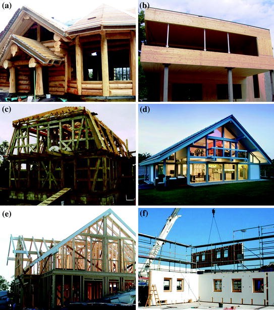
Overview of the basic structural systems in timber construction; (a) log construction, (b) solid timber construction, (c) timber-frame construction, (d) frame construction, (e) platform-frame construction, (f) panel construction; photograph by F. Kager
-
Solid timber construction (Fig. 3.15b)
-
Timber-frame construction (Fig. 3.15c)
-
Frame construction (Fig. 3.15d)
-
Balloon- and platform-frame construction (Fig. 3.15e)
-
Panel construction (Fig. 3.15f).

Log construction and solid timber construction can also be classified as massive structural systems since all load-bearing elements consist of solid elements. Other construction systems shown in pictures (c–f) consist of timber-frame-bearing elements and are therefore classified as lightweight structural systems. According to the load-bearing function, they can be subdivided into classical linear skeletal systems where all the loads are transmitted via linear bearing elements and planar frame systems where sheathing boards take over the horizontal loads. The classification of structural systems based on their load-bearing function is schematically presented in Fig. 3.16.

Classification of timber structural systems according to their load-bearing function
The following subsections offer a brief description of the above structural systems based on the main characteristics of the load-bearing behaviour of structural elements. Log and timber-frame construction systems are typical of traditional types of timber houses whose predominance in the past, especially in the countries with huge wooded areas and a strong timber tradition and industry, is now giving way to construction systems currently dominating the market, i.e., mostly to panel construction, solid timber construction and frame construction.
However, the main focus will be laid on the panel construction system whose detailed analysis in combination with the glazing is the subject matter of Chap. 4. As the panel construction system consists of timber-frame elements (studs and girders) and sheathing boards (panels), the term timber-frame-panel construction will be used a substitute in further parts of the book.
3.2.2 Massive Timber Structural Systems
3.2.2.1 Log Construction
Log construction is the most traditional type of timber construction, used in many countries in the world, especially in areas with cold climate conditions. Scandinavia, for example, is home not only to old residential buildings where log construction system was applied (see Fig. 3.17), but also to other structures, such as churches, towers. Furthermore, in the Alps and the mountainous regions of Central Europe, log construction usually plays an important role, especially for local inhabitants’ houses.

Traditional type of log construction
Log construction is classified as a massive timber structural system since its load-bearing elements consist of solid elements. Log construction is the most massive and usually the most expensive type of timber construction. The building’s envelope consists of a single leaf of horizontally stacked timber members (Fig. 3.18a) which need to perform a triple function, that of cladding, space enclosing and load bearing. Stability is achieved through the friction resistance in the bed joints, which makes the solid timber wall act as a plate, and through the cogged joints between the timber members at the corners, Deplazes [4]. The old-type system (Fig. 3.18a) usually requires no mechanical fasteners. A new type of connection, also called the “dovetail” joint, is mostly used in modern log buildings (Fig. 3.18b).

Types of connections in log construction; (a) the old type, (b) the new type
The traditional old types of log structures can seldom satisfy modern standards of the comfort of living or those of the energy efficiency. For example, the thermal transmittance of a 30-cm-thick wall made of solid conifer timber with no insulation amounts to \( U_{\text{wall}} = 0.40\,{\text{W}}/{\text{m}}^{2} {\text{K}} \), which is a higher value than required by modern standards. Such construction form is thus no longer as widespread as in it used to be in the past.
3.2.2.2 Solid Timber Construction
Solid timber construction (Fig. 3.15b), as one of the most widely used types of timber construction today, is a strong competitor to the frame-panel structural system, described in Sect. 3.2.3.4. Both types are prefabricated systems (Fig. 3.19) characterized by a very short platform erection time, which justifies the slogan “only two men to build a house”.

Platform-type erection in the massive panel timber construction, photograph by F. Kager
Nevertheless, from a structural point of view, there is an important difference between the above-mentioned systems. Due to its timber-frame bearing construction, the frame-panel system belongs to “Lightweight Timber Construction” (LTC), while the solid timber system with its solid panel composition falls into the category of “Massive timber construction” (MTC). Massive timber construction is more expensive, but it generally has higher horizontal stiffness and load-bearing capacity than the frame-panel construction and is therefore more appropriate for multi-storey timber buildings. In addition, with the MTC system, no vapour barrier is generally needed, which accounts for a higher heat storage capacity in comparison with LWC systems. The above facts could also be important in using timber and glass together with a view to achieving higher solar gains by inserting an optimal combination size of timber and glazing in the structure, cf. Sect. 4.2. All the listed facts have to be considered when choosing the most appropriate type of timber building.
There are many different types of contemporary massive solid timber constructions found all over the world. They can be subdivided into massive panel structural systems where glued panel floor and wall elements resist all the loads in the structure, and modular building block systems consisting of hand-size modular blocks.
3.2.2.2.1 Massive Panel System
There are many different types of massive panel structural floor and wall elements used as modular elements, usually built in standard dimensions, shown in Table 3.4.
An important and most frequently occurring massive construction type today is the massive panel system using wall and floor elements made from Cross-Laminated Timber (CLT) panels. In Switzerland, for example, the popularity goes to Leno solid panels. These are solid cross-laminated timber panels made from three to eleven fir plies glued together crosswise, Fig. 3.20. The resulting homogeneous, dimensionally stable and rigid component can be produced in sizes up to \( 4. 8\times 20\,{\text{m}} . \) Available thicknesses depending on the number of plies range from 50 to 300 mm, Deplazes [4].

LenoTec product with 5 spruce fir plies glued together crosswise, t = 135 mm, 5 plies
Wall elements in massive panel timber buildings consist of cross-laminated timber boards, known as “cross-laminated timber—CLT” or “Kreuzlagenholz—KLH” or “X-lam” (Fig. 3.21). Basic material for the production of CLT elements is sawmill-boards, whose quality is best if they are cut from the outer zones of the log. Such sideboards, which are not considered as particularly profit-making items by the millers, generally have excellent mechanical properties relating to stiffness and strength. The width of the boards needed for the production of CLT elements is usually 80–240 mm, with their thickness ranging from 10 to 45 and up to 100 mm (depending on the producer). The width to thickness ratio should be defined as b:d = 4:1. Timber species currently processed belong to conifers (e.g. fir, spruce fir, pine), which does not exclude deciduous trees (e.g. ash, beech) from being used in the future, Augustin [5].

Composition of a bearing timber construction in cross-laminated panels
The crossing of board layers results in good load distribution properties in both directions. The width of a wall element depends on the number of layers: 3, 5 or even 7. A typical three-layered wall element is 90–94 mm wide. Owing to the gluing of longitudinal and transverse layers, the “activity” of timber is reduced to a negligible degree.
Cross-laminated timber is a contemporary building material having more uniform and better mechanical properties than solid timber. It therefore represents not only an architectural challenge but also an important trend in the construction of modern, energy-efficient and seismic resistant single-family prefabricated houses and multi-storey prefabricated residential timber buildings. CLT is also suitable for offices, industrial and commercial buildings. On-site assembly methods of fully prefabricated wall elements are similar to those applied with timber-frame buildings and take an almost equal amount of time.
The size and form of CLT elements are defined by restrictions concerning production, transport and assembly. The existing standard dimensions of planar and single-curved elements are set at a length, width and thickness of 16.5, 3.0 m and up to 0.5 m, respectively. Longer elements (of up to 30 m) can be assembled by means of general finger joints. The thickness of lamellas in curved CLT elements has to be adjusted to the curvature, Augustin [5]. In general, the use of CLT elements is restricted to service classes 1 and 2 according to Eurocode 5 [6].
Insulation in cross-laminated timber wall elements is placed on the external sides of the bearing timber construction, as shown in Fig. 3.22. This is one of the most significant disadvantages of CLT wall elements in comparison with frame-panel wall elements. Producers usually offer a variety of massive panel elements of different thicknesses (see Table 3.5) which can be combined with different thicknesses of insulating materials to form wall elements having different thermal properties, according to the chosen type of the external wall element—that of low energy or passive standard. According to the data presented in Table 3.5, the composition of wall elements differs in the construction thickness of the load-bearing CLT structure as well as in that of insulation placed in the additional timber substructure whose usual thickness of 60 mm is by no means not the only dimension used in production.

CLT external wall elements; (a) normal type, (b) thermally improved element with additional insulation placed in the timber substructure
There are also some other types of solid panels wall and floor elements on the market which can be treated as box elements. For example, Lignotrend consists of three to seven cross-banded softwood plies with an average total thickness of 125 mm, where gaps of several centimetres separate individual pieces of the inner plies. The raw material is solely side boards or softwood. We can distinguish between elements opened on both sides (Fig. 3.23a), those closed on both sides (Fig. 3.23b) or just on one side (Fig. 3.23c). Wall elements are supplied in widths up to 625 mm, Deplazes [4] and Deplazes et al. [7].

Three different types of Lignotrend panel wall production; open on both sides (a), closed on both sides (b), closed on one side (c)
Typical characteristics of selected prefabricated solid timber panels made of CLT and box elements are listed in Table 3.5.
3.2.2.2.2 Modular Building Block System
One of the newest types of massive timber structural system is the modular building block system. Base load-bearing elements are small-format, factory-made modules of solid timber, usually in the form of building blocks. Modules are built up in a type of masonry bond following modular dimensions to form load-bearing internal and external walls (Fig. 3.24). Standardized bottom plates, modules, top plates and opening trimmers for standard doors and windows result in a coordinated building system, Kolb [3]. Owing to the modular form, this construction system with hand-size block technology has undergone considerable development and has already become quite widespread.

Modular building block system
3.2.3 Lightweight Timber Structural Systems
We can distinguish between two main load-bearing structural systems within lightweight structural systems:
-
Linear skeletal systems (timber-frame construction, frame construction)
-
Planar frame systems (balloon-frame construction, platform-frame construction, frame-panel construction).
The essential difference between the two systems is seen in the following facts: the sheathing boards or infill material in linear systems do not contribute to the resistance of the wall elements. All the loads are therefore transmitted via vertical (studs), horizontal (beams) and diagonal timber elements (Fig. 3.25a). On the other hand, in planar frame systems, the studs are placed close to each other thus allowing the boards to transmit the horizontal loads and be consequently treated as resisting elements (Fig. 3.25b).

Horizontal force distribution in (a) linear skeletal system, (b) planar frame system
3.2.3.1 Timber-Frame Construction
Timber-frame construction, seldom used today, is one of the traditional forms of lightweight timber structures. Timber-frame buildings found in many countries of Northern, Central and Eastern Europe exhibit numerous regional characteristics. This type of structural system commonly developed in regions where timber was not available in sufficient quantities required for log construction. Until the middle of the nineteenth century, most timber-frame structures had a visible load-bearing framework (and the infill panels). Bricks or clay bricks were usually installed to fill the spaces between timber elements forming the frame, where timber was based on a relatively small module with diagonal braces in the wall plane (Fig. 3.26). »Builders believed that this gave their buildings an improved fire resistance, but there was also a desire to give an “urban” look to timber construction, which was regarded as a “rural” form of construction«, Kolb [3].

Rural types of old timber-frame construction with a visible load-bearing frame
Timber-frame construction shows first signs of prefabrication (Fig. 3.27). Assembly of individual elements takes place on-site, storey by storey, with the horizontal loads transmitted via beams and diagonals directly to the base. The spacing between individual timber studs depends on the load-bearing capacity of timber sections which (in times before the industrialization) used to be cut to the required size by using simple tools. The vertical loads are transferred directly via contact faces between various timber members, Deplazes [4].

First signs of prefabrication in timber-frame construction
3.2.3.2 Frame Construction
From a structural point of view, frame construction could be regarded as the second type of linear skeletal systems where all loads are transmitted via vertical (studs), horizontal (beams) and diagonal elements (Fig. 3.25a). Stability is achieved by the inclusion of diagonal elements which usually extend through all the storeys. The load-bearing structure thus functions independently of the enclosing elements, such as façades or sheathing boards. The structure is therefore divided into two load-bearing substructures (Fig. 3.28):

Primary and secondary structural elements in frame construction
-
The primary structure
-
The secondary structure.
The secondary structure, consisting of timber floor or roof elements placed within small distances from each other, transfers the loads from the roof, the suspended floors and the walls to the main beams, which calls for relatively high floor elements.
The primary structure consists of the load-bearing columns and main beams, usually of rectangular cross sections. It carries the loads from the secondary structure and transfers these as concentrated loads to the foundations.
An old type of frame structure is the so-called post and beam construction (Fig. 3.29) where timber columns are placed within relatively large distances. Continuous beams of considerably large spans and cross-sectional dimensions are supported by one-level high columns, with additional corner diagonal elements being usually inserted in order to strengthen the flexible connection between both load-bearing elements and to assure the horizontal stability of the building. This type of frame construction is probably one of the oldest structural forms besides the log construction.

Post and beam structural system
The growing importance of timber construction in the fields of multi-storey and large-volume structures has helped modern frame construction, which is probably the most attractive current form of timber construction, to take on a new role in creating one of the most important and attractive types of timber structures of the present times. Although the mentioned classification of the elements to perform the secondary and primary load-bearing functions is not very economic in terms of material consumption, it does have its benefits since it leads to substantial flexibility in terms of the internal layout and design of the façade. Moreover, it opens a possibility of using longer spans with fewer internal columns than in other construction systems, which results in greater freedom of designing the interior layout. In addition to houses and other residential and public buildings, frame construction is suitable for offices, industrial and commercial buildings, Kolb [3].
Since the load-bearing functions in the frame system belong to the timber-frame elements and diagonals and due to longer spans, additional requirements for timber members arise. For instance, there is a preference to use glued-laminated timber for timber frames instead of the classic sawn timber. On the other hand, the sheathings and the timber frame do not have any resisting function which is performed by the diagonals. Consequently, the walls with a higher number and an enlarged size of openings can be used (Fig. 3.30).

Frame structural system—walls with an enlarged size of openings can be used in timber buildings
Frame structure is probably the most advanced structural type of timber buildings today. Satisfying most of the energy-efficiency demands, whose detailed description and explanation are part of Chap. 2, the frame structure is ideal for combining timber and glass, which can lead to designing highly attractive buildings. The timber frame is a fully resisting part of the building where the two materials are combined, while the glazing has no load-bearing function but assures solar gains and the transparency of the building. In addition to an attractive design, such buildings offer a most comfortable indoor living climate.
Furthermore, two vitally important facts, which will be further discussed in Sects. 3.4 and 4.4 need to be stressed. Firstly, owing to a rather low impact of the horizontal loads in one-storey houses, there is usually no need for additional diagonals to assure the horizontal stability of the structure (Fig. 3.31a). On the other hand, a strong impact of the horizontal loads in multi-storey buildings calls for the insertion of diagonal elements, which remain visible, to assure the horizontal stability of the building (Fig. 3.31b).

Large glazing surfaces in timber buildings: (a) one-storey house designed in a study workshop Timber low energy house and (b) single-family house in Hohe Wand, Austria, designed and photograph by Architekturbüro Reinberg ZT GmbH Vienna
3.2.3.3 Balloon-Frame and Platform-Frame Construction
As far as the statics is concerned there is almost no difference between the balloon-frame and the platform-frame constructions. In both structural types, the closely spaced studs with squared sections, usually of standard sizes, are placed within a constant distance range. Connecting the boards to the timber studs takes place on-site after the erection of the timber structures. As far as the force transmission is concerned, both construction types can be treated as planar frame systems since the sheathing boards have an important load-bearing function in transmitting the horizontal load (Fig. 3.25b) and assure the horizontal stability of the structure.
Yet, from the technological viewpoint, there is a significant distinction between the two construction types. In the balloon-frame construction (Fig. 3.32a), the function of the main load-bearing part is taken by the frame composed of beams and pillars following a continuous bottom-to-roof pattern. The joists of suspended floors are supported by a horizontal binder inserted into notches cut in the vertical studs. All connections are usually fastened with nails. The maximum height of pillars is limited to approximately 8 or 10 m, which makes the balloon-frame construction suitable solely for one or two-storey buildings. This construction system is particularly well known in North America. In Europe, the timber stud construction with a slightly lesser degree of prefabrication is the equivalent of the American balloon frame.

Balloon-frame construction with continuous vertical studs (a) and platform-frame construction with storey-by-storey assembly (b)
In the platform-frame construction (Fig. 3.32b), the load-bearing timber frame consists of storey-high preassembled studs with square sections. Individual load-bearing frame elements are assembled at the prefabrication stage and transported to the construction site as self-contained elements. In the following stage, the boards are connected to the timber frame to assure the horizontal stability of the building. The construction of platforms is a step-by-step procedure.
The main advantage of both structural types is a considerably low weight of the building. However, Europe has witnessed a major replacement of the two construction types with the frame-panel construction where prefabrication encompasses a more significant part of the construction process.
3.2.3.4 Frame-Panel Construction
The frame-panel system originates from the Scandinavian-American construction methods, i.e., balloon-frame and platform-frame construction types whose assembly works take place on-site. Advantages of the frame-panel construction system over the above-mentioned traditional timber-frame construction systems were first noticed at the beginning of the 1980s of the previous century and made a significant contribution to the development of such timber construction. The benefits to be pointed out lie in factory prefabrication (Fig. 3.33) assuring the so-called ideal weather conditions in addition to constant supervision over construction works and the built-in materials. Another asset is the subsequently faster assembly process as the ready-made elements are crane-lifted to be erected onto the foundation platform, adjusted and screw-fastened.

Production of load-bearing wall elements in a factory
Besides having good constructional characteristics, the panel construction system offers a series of additional advantages among which indoor climate of timber buildings is of major importance since the built-in materials are natural, people-friendly and demand very little energy for their provision. The panel construction system’s priority over massive masonry construction is seen in thinner wall elements, which can result into an increase in the usable floor area by 10 %, with the total surface area of a building being the same.
Furthermore, the transition from the single-panel construction system (Fig. 3.34a) to the macro-panel construction system (Fig. 3.34b) means an even higher assembly time reduction and higher stiffness of the entire structure due to a lesser number of joints. The wall elements with a total length of up to 12.5 m are now entirely produced in a factory (Fig. 3.33).

Single-panel construction system (a) and macro-panel construction system (b)
The basic vertical load-bearing elements in the frame-panel construction, which is nowadays typical of Central Europe, are the panel walls consisting of the load-bearing timber frame and the sheathing boards, while the horizontal floor load-bearing function goes to slabs made of the floor beams and the load-bearing wood-based sheathing boards connected to the upper side of the floor beams. The construction is a systematic storey-by-storey creation of a building; after the walls have been erected, the floor platform for the next level is built. The usefulness along with the popularity of this system in the case of multi-storey buildings has generated a growing interest in its application around the world.
Prefabricated timber-frame walls functioning as the main vertical bearing capacity elements, whose single panel typical dimensions have a width of b = 1,250 mm and a height of h = 2,500–3,100 mm, are composed of a timber frame and sheets of board-material fixed by mechanical fasteners to both sides of the timber frame (Fig. 3.34). There are many types of panel sheet products available which may have a certain level of structural capacity such as wood-based materials (plywood, oriented strand board, hardboard, particleboard, etc., or fibre-plaster boards). Their use originally started in Germany and these products have recently become the most frequently used types of board-materials in Central Europe. A thermo-insulation material, whose thickness depends on the type of external wall, is inserted between the timber studs and girders. The sheathing boards on both sides of the wall can be covered with a 12.5-mm gypsum–cardboard.
In the frame-panel construction, the entire wall assemblies, including windows, doors and installations, are fully constructed in a horizontal plane (Fig. 3.35a) in the factory and then put in vertical position (Fig. 3.35b).

The walls with openings are constructed in horizontal position (a) and then put in vertical position (b)
Producers usually offer a variety of composite construction wall elements of different types related to energy efficiency. In Central Europe, the most common type of production of the external walls of low energy-efficiency standard is the timber frame with a thickness of 160 mm. The whole composition, labelled as TF-1, is presented in Table 3.6. The improved type with an additional timber substructure and insulation of 60 mm is labelled as TF-2. The passive type of the external wall is labelled as TF-3. The cross sections are graphically presented in Fig. 3.36a, b and c.

Composition of three typical timber-frame external macro-panel wall elements; low-energy system (a) improved low-energy system with installation layer (b) passive system (c)
A difference in the insulation properties of the wall elements, such as the insulation thickness, the number of insulating layers or the insulation type can be observed in the above table. Consequently, the thermal transmittance of the three wall elements (U wall–value) differs as well.
As the erection of buildings constructed in the frame-panel structural system follows the platform technology, the height of the wall elements is equal to that of the storey. In residential buildings, the height usually ranges from 2,500 to 2,700 mm. On the other hand, the relevant height in public and commercial buildings may exceed the previously mentioned numbers. The maximal height of the prefabricated wall assembly constructed in the macro-panel system is limited—it depends on transportation requirements and consequently on the total length of the wall assembly. Maximal dimensions given in Table 3.7 and are graphically presented in Fig. 3.37.

Maximal dimensions of prefabricated wall assemblies
The wall elements are usually prefabricated in standard modular dimensions, with commonly used 625 mm spans between the timber studs (Fig. 3.38). However, to satisfy architectural design requirements for special forms of buildings, exceptions can be adopted in, e.g., window and door openings, fixed glazing areas. When such exceptions take place, the wall elements next to the opening or those at the end of the whole assembly are usually cut to get the required dimension.

Modular dimensions in prefabricated frame-panel wall elements, dimensions in cm
3.3 Design Computational Models
The main elements transferring forces to the foundation in prefabricated timber-frame-panel structures are timber-frame-panel walls which belong to the single-panel system (Fig. 3.34a) or to the macro-panel system (Fig. 3.34b).
The vertical load (dead load, live load, snow, etc.) impact is calculated as axial compression parallel to the grain in the timber-frame studs. The above impact, however, is not the subject of the present publication.
The focus of this section is on the horizontal load (wind, earthquake) distribution to the load-bearing elements of the frame-panel construction. In a structural system consisting of vertical prefabricated walls and prefabricated slabs acting as rigid diaphragms, horizontal displacements at the top of a storey due to horizontal loads are constant along a wall assembly. The horizontal load is thus distributed to wall assemblies and further to individual wall elements according to their stiffness ratios (Fig. 3.39).

Force distribution under the horizontal load in the timber-frame-panel building, adopted from Kolb [3]
The platform-frame and balloon-frame constructions have a similar load distribution. A sole technological distinction is that of the elements not being prefabricated but usually erected on-site.
In the past, many computational models were suggested to calculate the horizontal load distribution in timber-frame-panel wall assemblies. As described in Breyer et al. [8], Faherty and Williamson [9], Thelanderson and Larsen [10], Schulze [11] and Eurocode 5 [6], the most common way to calculate structural behaviour in the timber-frame-panel wall assembly under the horizontal load is to assume that each floor platform is rigid, with each timber-frame wall being a vertical cantilever beam fixed at the bottom and free to deflect at the top (Fig. 3.40). Both supports approximate the influence of the neighbouring panel walls and assure a boundary condition for the wall in question. The supports can be considered rigid (Fig. 3.40), as seen in Faherty and Williamson [9] and Eurocode 5 [6], or flexible, which is more realistic in addition to being more accurate and will be further presented and discussed in Sect. 3.3.1.

Static design for a wall assembly on individual storey
Each wall assembly at individual levels consists of separate wall segments acting as individual cantilevers, where every segment is determined with the width b of the sheathing board (usually 1,250 mm). As mentioned beforehand, if the lateral forces acting at the top of the element are considered to be uniformly distributed to each segment, the horizontal force acting on a single wall element can be calculated as F H = F H,tot/n. Since only the segments with the full wall height having no window and door openings are usually taken into account for the calculation, the value n represents the number of single-panel wall elements without any openings (Fig. 3.40).
Many design computational models have been proposed in order to analyse and predict the racking resistance of the timber-frame wall subjected to the lateral loads. According to the accuracy of approach, they can be subdivided into the following groups:
-
FEM models
-
2D-braced frame models with fictive diagonals
-
Semi-analytical simplified shear models
-
Semi-analytical simplified composite beam models.
A good mathematical model is crucial for quick and accurate calculations in the case of architecturally more complex and irregularly shaped buildings with a substantial number of wall elements. Mathematical models differ in their accuracy and simplicity and consequently also in the level of suitability for application in practice. The major problem of the timber-frame wall elements is mechanical fasteners which are unable to provide a fully rigid connection. The flexibility of fasteners in the connecting plane between the timber frame and the boards should therefore be taken into account in modelling such wall elements.
The most accurate way of modelling timber-frame walls is the Finite Element Method (FEM) where the simulation process replaces the timber frame with line elements, the sheathing board with shell elements and the staples with spring elements. Drawbacks of the above approach are its time-consuming nature and unprofitability in addition to its requirement for using specific and more expensive programs. FEM is more suitable for scientific purposes, while in practice simpler and cheaper programs with no special modulus for the described simulation are seen as more adequate and should be therefore given preference.
In civil engineering practice, two-dimensional (2D)-braced frames are frequently used. Their advantage over other models is the possibility of using simpler and cheaper software with a relatively fast modelling stage. Moreover, with properly defined dimensions of fictive diagonals and supports, braced frames offer a very good approximation the real situation.
Engineering practice also encompasses more useful and simplified methods using a semi-analytical approach. No specific software is needed for the calculation of the results, as hand calculation suffices but they require some important and strong simplifications which call for careful consideration. A thorough presentation of the above methods follows in Sects. 3.3.3 and 3.3.4.
3.3.1 FEM Models
The process of modelling timber-frame wall elements under the horizontal load by using the finite element method is the most accurate and the most complex approach. Applying the FEM allows for the influence of openings and fixed glazing on the lateral resistance and stiffness of the wall elements to be taken into consideration, which is vital for our further study presented in Sect. 4.4. Yet, with an opening in the wall element, frame-type instead of beam-type behaviour is expected and the semi-analytical beam model presented in Sect. 3.3.4 is consequently not applicable. A numerical study using the FEM analysis, presented at the end of this subsection, was therefore performed by Kozem Šilih [12]. It encompassed the wall elements along with the influence of any possible window or door openings. The FEM modelling of the timber-frame walls calls for additional consideration of the following items which exert significant influence on the horizontal resistance and stiffness:
-
Flexibility of mechanical fasteners connecting the boards and the timber frame
-
The appearance of cracks in the tensile area of the fibre-plaster boards—when fibre-plaster sheathing boards are used
-
The influence of potential flexibility of the surrounding wall elements
-
The influence of openings or that of fixed glazing in the wall element
-
The influence of inserted steel or carbon diagonals in the case of strengthening the wall elements.
The wall elements studied were modelled and analysed by using the commercial FEM computer software SAP 2000 (2010), which is more thoroughly presented in Kozem Šilih [12] and Kozem Šilih and M. Premrov [13], while the current subsection focuses only on the most important facts of the modelling.
Behaviour of the analysed wall elements is largely tied to the properties of the sheathing material, i.e., to its possible low tensile strength in the case of fibre-plaster boards, and the consequent appearance of cracks. The sheathing material is therefore modelled as linear elastic in compression, while in tension a stress drop occurs when the characteristic tensional resistance (f bt) is reached, corresponding to the model of brittle failure. The sheathing boards are modelled by using the nonlinear shell elements. According to the definition of the applied shell elements, nonlinear behaviour is accounted for by two decoupled 1D models: one for the horizontal direction, and one for the vertical direction.
The timber-frame material is considered as an isotropic elastic material (with the modulus of elasticity E 0,mean), and the elements of the timber frame are modelled as the simple plane-stress elements. Due to their geometry, the timber members behave predominantly as beam elements with the normal stresses acting parallel to the grain, while the normal stresses in the perpendicular direction are negligible.
Mechanical fasteners connecting the timber frame and the sheathing boards also require an in-depth discussion. The fasteners are modelled using the nonlinear link elements (springs) with a multi-linear elasto-plastic force–displacement relation (Fig. 3.41). In order to take into account the general in-plane link between the connected elements, two perpendicular uncoupled 1D springs are used for each fastener.

Geometry of the numerical model of the wall element (left elevation, right cross section with the springs simulating the fasteners)
According to Eurocode 5 [6], the shear stiffness (i.e. the slip modulus K) of the fasteners at a specific point depends on the current value of the shear force (V z ). The corresponding three-linear diagram (Fig. 3.42) for the slip modulus K is therefore introduced into the model. The presented numerical model encompasses a simplified shear force-slip modulus with a constant value of the slip modulus through each phase, indicated by the dashed line in the figure.

Three-linear diagram for the slip modulus (K) of the fasteners (staples)
The supporting conditions (Fig. 3.41) follow the setup for experimental tests and are defined according to Eurocode 5 [6]. The tensile support (bottom left) is arranged using three bolts and two steel plates (one on each side of the wall element). The steel plates are connected to a rigid steel frame. In the numerical model, the bolts are considered as linear elastic spring supports with the stiffness equal to that of the slip modulus (K ser) for bolts. The steel plates are not included in the numerical model. The compressive support (bottom right) is modelled using rigid point supports (Fig. 3.41).
Our further study concerning the influence of fixed glazing on the horizontal resistance and stiffness of the wall follows in Sect. 4.3. Yet, at the present stage, the first step is to focus on the influence of window or door openings, with no sheathing material in the area of the opening. The geometry of the analysed wall elements is shown in Fig. 3.43.

The geometry of the elements O1 (left) and O2 (right) (the unit of measurement = cm)
The elements consist of a timber frame and are coated on both sides with single fibre-plaster boards having a thickness of t = 1.5 cm. The cross-sectional dimensions of the elements of the timber frame amount to 8/9 cm (the lower and the upper beam), 9/9 cm (the side vertical studs) and 4.4/9 cm (all internal beams). The sheathing boards are connected to the timber frame with steel staples. An average intermediate distance between the staples amounts to 7.5 cm, with the exception of the intermediate stud in element G2 and the intermediate studs bellow the openings in elements O1 and O2 where the distance between the staples is 15 cm. Details concerning timber in fibre-plaster materials used are given in Table 3.8.
In view of a better understanding, the numerical results obtained for the wall elements with openings (O1, O2, OM and OV) are compared to those without any openings (G2) without any openings (Table 3.9). In addition to the values of the force at which the first crack is observed in the fibre-plaster board (F cr) and the ultimate capacity—total failure of the test sample (F u ), two additional quantities are dealt with:
-
The initial stiffness K i , defined as the ratio between F cr and the corresponding displacement w cr at the formation of the first crack; K i thus corresponds to the average stiffness in the range of elastic behaviour (i.e. the region of reversible deformations).
-
The value of the force (F wt) at which the defined target displacement w t = H/500 = 13.20 mm is reached; the target displacements are defined with respect to the regulations on the limitations of inter-storey drifts set by the European code for the design of earthquake-resistant structures, Eurocode 8 [14].
The results for the failure force (F wt) at the ultimate displacement (w t ) according to Eurocode 8 [14] and those for the deflection (w) under the horizontal force at the top of the wall element are obtained by using the described procedure on the samples (Fig. 3.44). Further details and analysis of the numerical results can be found in Kozem Šilih [12].

F-w diagrams with the values of forces at the target displacement w t (0, 5 % of the storey height)
As mentioned above, a large proportion of walls (over 50 %, or even up to 80 %) may consist of elements with openings. A simple calculation based on the results presented in Fig. 3.44 shows that in a wall without any openings (G2)—50 % and those with openings (O1)—50 %, approximately 13 % of the entire horizontal load would be transmitted to O1 elements. In the case of a wall with 80 % of elements O2 (and 20 % of G2), the ratio of the force resisted by elements O2 rises to 54 %. Elements with openings may transmit a considerable share of the horizontal load, depending on the number and types of different elements in the wall system.
The following are highly significant conclusions drawn about the influence the openings exert on structural behaviour of timber-frame buildings under the horizontal load:
-
In the initial phase, the structure is elastic. Additional stiffness provided by the wall elements with openings results in a decrease in the load to which the solid elements are exposed and the first cracking occurs at a higher value of the horizontal load. The elastic resistance of the structure (until the point of the formation of irreversible damage) is therefore improved.
-
After the formation of the cracks in the full wall elements, the elements with openings remain elastic for an additional amount of time, which leads to the ductility of the structure being improved. Additional stiffness provided by the wall elements with openings in the post-elastic phase also results in a higher value of the ultimate load. Consequently, both the ultimate resistance (as a means of preventing structural collapse) as well as the so-called over strength capacity of the wall system are increased.
The above conclusions are of utmost importance and will serve as starting points in our further study in Sect. 4.4.
3.3.2 Two-Dimensional-Braced Frame Models
Timber-frame wall elements can be modelled as a sophisticated and most accurate finite element model—as a shell element model, or as a braced frame with one or two diagonals. In the past, two-dimensional (2D) braced elements were already used by different authors. Timber-frame wall modelling in prefabricated timber structures was presented by Kessel and zur Kammer [15] who introduced a truss model with two diagonals to simulate every wall panel. Horizontal stiffness of the wall was defined by the stiffness of the diagonals whose choice satisfied the following condition: the horizontal displacement at the top of the panel due to a horizontal action of 8 kN was H/500, where H represented the height of the wall element. zur Kammer [16] offers five different models to simulate timber-frame walls with a special computational program. The problem of modelling timber-frame walls was also discussed in Kessel and Schönhoff [17] who used a braced frame with a single fictive diagonal. The cross section and the modulus of elasticity of the diagonal were determined based on the assumption that deformation of the alternative system is equal to that of the shear field of the sheathing board. The shear stiffness of the shear field was calculated numerically, with the fasteners’ distance being taken into account.
But none of the presented mathematical models for timber-frame walls includes both the bending and shear deformability of the timber-frame wall simultaneously. Such approach can be found in Pintarič and Premrov [18], where the problem of modelling is avoided with a braced frame model having one fictive diagonal (Fig. 3.45). Its effective cross section approximates the bending and the shear stiffness of the sheathing board as well as the flexibility of the fasteners. A braced frame acts as the cantilever beam with two rigid supports (Fig. 3.45). The cross section of the fictive diagonal is determined by the bending and shear stiffness of the timber-frame wall calculated with respect to Eurocode 5 [6], where the effective bending stiffness (EI y )eff is determined by the »γ-method«, presented in Eq. (3.14). The flexibility of the fasteners is calculated through their stiffness coefficient γ y , determined for mechanically joint beams, based on Eurocode 5 [6].

Mathematical model of the timber-frame wall with one fictive diagonal
We proceed from the assumption that the horizontal displacement u H of the existent timber-frame wall is equal to that of the model with the alternative diagonal, when the same horizontal force F H is acting on both systems. We furthermore presume that the axial stiffness of the surrounding frame is high enough to eliminate the impact of the frame, which would leave the flexibility of fictive diagonal as the only element to be taken into account.
Any material or cross section can be chosen for the fictive diagonal. The following is an example of a diagonal with a circular cross section, where the axial stiffness k d of the fictive diagonal is determined as follows:
with E D being the modulus of elasticity of the diagonal, A d,fic the fictive cross section of the diagonal and L d the length of the diagonal. The connection between the stiffness of the existent timber-frame wall (k p ) and the stiffness of the fictive diagonal (k d ) is derived according to Fig. 3.46 and with the prediction of small displacements u H . A final expression for the relation between k p and k d is given in the form of

Scheme of the force distribution in a timber-frame wall element
Combining Eqs. (3.6) and (3.7) gives the expression for the cross section of the fictive diagonal A d,fic:
The diameter d fic of the fictive diagonal of the circular cross section is then defined as follows:
Based on the assumption of equal horizontal displacements of the existent timber-frame wall and the model with the fictive diagonal, we can claim that the axial stiffness of the diagonal is directly connected with the stiffness of the timber-frame wall obtained by the analytical calculation. As seen in Eq. (3.9), the cross section of the fictive diagonal A d,fic includes and simulates random staple distance seff, cracks of the sheathing boards (with EI eff being reduced) as well as the openings and fixed glazing (with the reduced stiffness of the timber-frame wall). The height of the timber-frame wall, timber quality, the dimension of the studs and the type of the sheathing board can also be randomly selected.
3.3.2.1 Accuracy of the Model: Numerical Example
Horizontal displacements of the timber-frame wall at the horizontal force F H = 10 kN, calculated through a mathematical model with the fictive diagonal, are compared with the already known displacements from previous FEM models described in Sect. 3.3.1. Table 3.10 features a comparison of the displacements for different staple distances (37.5, 75 and 150 mm) obtained by using the following procedures:
-
The finite element method using the SAP 2000 program, taken from Kozem Šilih et al. [13]
-
Experimental studies taken from Premrov and Kuhta [19].
The above table shows highly comparable values of horizontal displacements obtained through different methods. If the finite element model is taken as the most accurate, the deviation of the horizontal displacement in the braced frame with the fictive diagonal from that in the FEM model ranges from 0.9 % for the staple distances of 150 mm to 8 % for the distance of 37.5 mm. The difference is small in number, although rather significant in terms of a time-saving aspect and simplicity of the model.
To sum up, the mathematical model with the fictive diagonal offers a very good approximation in the calculation of the timber-frame wall element horizontal stiffness. The simplicity makes this model applicable also in combination with easily manageable and cheaper programs. In addition, a lot of time is saved in comparison with more complex and detailed modelling with the finite element method using more expensive and complicated programs, as presented in Sect. 3.3.1. When braced frames are combined, the entire system behaves as a structure made of separate independent cantilever beams modelled with the help of fictive diagonals. Braced frame modelling requires the knowledge of the bending and shear stiffness of the wall element which is determined with the analytical calculation, according to Eurocode 5 [6] and a semi-analytical procedure described in Premrov and Dobrila [20]. Walls with a different stiffness value are modelled with fictive diagonals of different thickness. Eventual appearance of the cracks in the fibre-plaster boards is simulated by reducing I b and using the mathematical model from Premrov and Dobrila [20]. Another benefit of this method, vitally important for our study presented in Sect. 4.3, is its suitability for timber-frame wall elements with openings or fixed glazing, where the reduced stiffness of the wall is simulated with an adequately reduced diameter of the fictive diagonal.
3.3.3 Semi-Analytical Simplified Shear Models
In practice, there is often a need for simple and useful expressions to determine the racking resistance of the timber-frame walls by using hand calculation only, without recourse to computational programs. Two examples of such models will be presented in Sects. 3.3.3 and 3.3.4.
Källsner [21] and Äkerlund [22] suggested an interesting approach to determine the load-bearing capacity of the wall unit, based on two major assumptions:
-
Behaviour of the joints between the sheet and the frame members is assumed to be linear elastic until the point of failure.
-
The frame members and the sheets are assumed to be rigid and hinged to each other.
Furthermore, two simplified computational methods are given in Eurocode 5 [6] in order to determine the load-bearing capacity of the wall diaphragm. The first, Method A, is identical to the “Lower bound plastic method”, presented by Källsner and Lam [23]. It defines the characteristic shear resistance of the wall (F v,Rk) as a sum of all the fasteners’ shear resistance values (F f,Rk) along the loaded edges, based on the assumption that the timber-frame members and the sheets are rigid and hinged to each other:
The second simplified analysis, Method B, is applicable only to walls made from sheets of timber-based panel products fastened to the timber frame by means of nails or screws, with the fasteners being evenly spaced around the perimeter of the sheet. According to Method A, the sheathing material factor (k n ), the fastener spacing factor (k s ), the vertical load factor (k i,q ) and the dimension factors for the panel (k d ) are included in the design procedure in the form of:
where d is the diameter of the fastener and ρ k the characteristic density of the timber frame. A scheme of the force distribution in a timber-frame wall unit under the horizontal force acting at the top of the element is presented in Fig. 3.46.
Eurocode 5 [6] simplified methods are said to be suitable for any fastener spacing commonly used in production in the case of using timber-based sheathing boards. However, these methods are not applicable in cases where the fibre-plaster sheathing material is used and where the tensile strength is very low as the cracks usually appear before the stresses in the fasteners achieve the yielding point. Källsner and Girhammar [24] developed an elastic analysis model for fully anchored sheathed timber-frame shear walls with timber-based sheathing boards. The model is based on the assumption of a linear elastic load-slip relation for the sheathing-to-framing joints. To suit the requirements of a special commonly appearing case, where h i = 2b i and s = s r = s p = s is/2, the authors developed a simplified expression for the horizontal load-bearing capacity (F H ) in the form of
where F v denotes the shear capacity of the fastener. If the lateral stress on the fastener achieves the characteristic yield point, the expression approximates Eq. (3.11a) defined by Eurocode. The authors additionally studied the effect of flexible framing members, as well as the effect of shear deformation of the sheet and that of vertical loads.
3.3.4 Semi-Analytical Simplified Composite Beam Models
The treated wall elements consisting of the timber frame and the sheathing boards behave in reality as composite elements and should thus be analysed as such. With the (sheathing) board taking the function of a coating material, the horizontal load shifts part of the force via mechanical fasteners to the fibre-plaster boards and the wall acts as a deep composite beam. Distribution of the horizontal force in composite treatment of the element depends on the proportion of stiffness. The effective bending stiffness \( (EI_{y} )_{\text{eff}} \) of mechanically jointed beams, which empirically considers the flexibility of fasteners via coefficient γ y —taken from Eurocode 5 [6], can be written in the form of
where n is the total number of elements in the relevant cross section, and a i is the distance between the global y-axis of the entire cross section and the local y i -axis of the ith element with a cross section A i (see Fig. 3.47). The equation shows that the bending stiffness \( \left( {EI_{y} } \right)_{\text{eff}} \) strongly depends on the stiffness coefficient of the fasteners (γ y ). With respect to Eurocode 5, γ y can be defined via the fastener spacing (s) and the slip modulus per shear plane per fastener (K) in the form of

Mathematical model and the normal stress distribution in the cross section
The expression of the so-called “γ-method” is based on the differential equation for the partial composite action with the following fundamental assumptions:
-
Bernoulli’s hypothesis is valid for each subcomponent.
-
The slip stiffness is constant along the whole connecting area in the element.
-
Material behaviour of all subcomponents is considered to be linear elastic (Fig. 3.47).
The simplified solutions are closely related to Möhler’s model [25] which takes into consideration the fact that a beam is simply supported and has constant slip stiffness. Four basic assumptions have been additionally considered through modelling of the cracked cross section in the sheathing boards of the composite beam model, Premrov and Dobrila [20]:
-
The tensile area of the boards is neglected after the first crack formation.
-
Linear elastic material behaviour of the compressed area of the boards and the timber frame is assumed.
-
The stiffness coefficient of the fasteners in the tensile connecting area (γ yt,mod) is presumed to remain constant after the appearance of the first crack.
-
The stiffness coefficient of the fasteners in the compressed connecting area (γ yc,mod) is not constant and depends on the lateral force acting on a single fastener.
An approximate semi-analytical mathematical model is schematically presented in Fig. 3.47. Using the classical beam theory the characteristic horizontal force forming the first tensile crack (F cr,k ) in the sheathing board is defined according to the normal stress criteria and the characteristic tensile strength of the board (f bt,k ):
If we declare a characteristic destruction condition of the wall element the failure case when the tensile stress in timber (σ tt,max) achieves the characteristic tensile timber strength (f t,0,k ), the characteristic horizontal destruction force (F u,k ) is computed in the following form:
where \( \left( {EI_{y} } \right)^{II}_{\text{eff}} \) represents the effective bending stiffness of the cross section with a crack in the tensile section of the board (Fig. 3.47). Thus, the lateral force (F 1) acting on a single fastener in a single shear can be calculated in dependence on the horizontal point load (F H ):
As designers and producers usually find themselves in an important dilemma of deciding upon the best sheathing board (OSB or FPB) to be used in a building according to its height and location, our further attention will be focused mainly on the analysis of the sheathing boards’ influence on the racking resistance of the wall elements. The results will serve as confirmation of the applicability of both simplified models presented. A detailed numerical study of the above issue can be found in Premrov and Dobrila [26].
Numerical analyses are performed on the wall element with dimensions of h i = 2,635 mm and b i = 1,250 mm, consisting of timber studs (20 × 90 × 90 mm and 10 × 44 × 90 mm) and timber girders (20 × 80 × 90 mm). The sheathing boards (OSB or FPB) with a thickness of t = 15 mm are fixed to the timber frame by means of staples with a diameter of d = 1.53 mm and a length of l = 35 mm. The composite cross section of the element is schematically presented in Fig. 3.48. Eurocode 5 [6] sets the minimum spacing for staples at \( a_{{1,{ \hbox{min} }}} = \left( {\left. {10 + 5} \right|\left. {cos\,\alpha } \right|} \right)d = 15d = 22.95\,{\text{mm}} \). Our analysis will therefore be presented with respect to the above range.

Cross section of the test sample
Material properties of timber with a strength grade C22 are taken from EN 338:2009, FPB material properties originate from Knauf [27] and those of type 3-OSB from Kronopol [28] and EN 300:2006 [36]. All the values are listed in Table 3.11.
Both calculated characteristic racking resistances in dependence of the fastener spacing (s), obtained through Eq. (3.10a) for the wall element with OSB sheathing boards and through Eq. (3.15a) for the wall element with FPB sheathing boards, are graphically presented in Fig. 3.49a and b. The values measured for FPB are taken from Premrov and Kuhta [29]; they were obtained with test samples having the same material characteristics and dimensions as those in the numerical study.

Characteristic racking resistance of the wall in dependence of the fasteners’ spacing (s) (a) DSB (b) FPB
As seen from Fig. 3.49a, the value F v,Rk in the case of OSB sheathing boards is far under the force causing the first crack in the board (F cr,k ) at any value of the fastener’s spacing (s). The reason lies in the fact that the tensile strength of OSB boards is relatively high and equal to the compressive strength (see Table 3.11). According to Eq. (3.15b), the value obtained for F cr,k is unrealistically high and should not be considered. Consequently, the fastener yielding in the wall elements with OSB boards is decisive for almost any value of s, which calls for Eq. (3.10a) to be used. The difference between the values for F cr,k and F v,Rk strongly depends on the fastener’s spacing and proves to be smaller at a lower value of s.
In FPB sheathing boards (Fig. 3.49b), there is evidence of both methods being in relatively good agreement only at the fastener spacing ranging from 100 to 150 mm. However, it needs to be underlined that such spacing is usually not used in production. The case of FPB sheathing boards demands a particular respect of the values obtained through the composite beam model on account of their better comparability with the measured values.
To sum up the current subsection, it would be interesting to compare the racking resistance with the values obtained by expressions which are decisive for each type of sheathing boards. According to F v,k , the shear model is decisive for the walls with OSB sheathing, while the composite beam model has a decisive role in FPB sheathing boards, according to F cr,k . The functions of F Rk in dependence of s are presented in Fig. 3.50.

Racking resistance of walls with FPB and OSB sheathing boards
It is obvious that the racking resistance for FPB is far under the values for OSB. The difference increases with a smaller fastener spacing. In addition, fastener spacing has a stronger influence on the wall elements with OSB sheathing boards.
3.4 Multi-Storey Timber-Frame Building
There is a worldwide increasing tendency to build multi-storey (three and more) prefabricated timber-frame buildings with timber-frame wall panels functioning as the main bearing capacity elements. A Slovenian example is a six-storey Hotel Dobrava on the Pohorje Mountain, built in 2000 (Fig. 3.51), with overall ground plan dimensions of 38 × 18.60 m, Premrov [30]. The first two storeys, of which one is underground, were built in a classical system with thin concrete walls. The rest of the buildings, the upper four storeys, were erected in the timber-frame-panel wall system, thoroughly described in Sect. 3.2.3.4.

A six-storey Hotel Dobrava in Terme Zreče, the Pohorje Mountain, Slovenia
Seismic and windy areas witness an essential increase in the horizontal load actions and a consequent direct, strong impact on the internal forces in the load-bearing timber-frame-panel wall elements. For a wall assembly placed in one principal direction, consisting of one or more wall elements, a simplified static design presented in Fig. 3.52 can be used to calculate the axial forces (N), the shear forces (V) and the bending moments (M) due to vertical and horizontal loads.

Static design for the horizontal load action in one principal direction for the frame-panel building of Hotel Dobrava
The force acting at the top of a single wall element is obtained by using the procedure presented in Sect. 3.3, Fig. 3.40. As mentioned in Sect. 3.3.4, the timber-frame-panel walls with fibre-plaster sheathing boards (FPB) can be treated as composite elements. Distribution of the horizontal force through composite treatment of the element depends on the proportion of the stiffness. As the tensile strength of the FPB is approximately 10 times lower than the compressive strength, and evidently smaller than timber strength of all members in the timber frame, the FPB usually act as a weaker part of the presented composite system. Thus, multi-storey buildings located in seismic or windy areas usually face the appearance of cracks in the FPB. The latter consequently lose their stiffness and their contribution to the total horizontal stiffness of the whole wall assembly should therefore not be taken into account. Stresses in the timber frame under the horizontal loads are usually not critical. In such cases, it is necessary to strengthen the wall elements to assure the horizontal stability of the structure. There are several possibilities of reinforcing arrangements:
-
Using additional boards which are usually doubled:
-
Symmetrically (on both sides of the timber frame)
-
Non-symmetrically (on one side of the timber frame)
-
-
By reinforcing boards with steel diagonals
-
By reinforcing boards with carbon or high-strength synthetic fibres (FRP, CFRP, etc.).
In Dobrila and Premrov [31], experimental results using additional fibre-plaster boards (FPB) are presented. The test samples demonstrated higher elasticity, while the bearing capacity and ductility, in particular, were not improved in the desired range.
With the intention of improving the resistance and, especially, the ductility of the walls, it is more convenient to insert classical diagonal steel strips which have to be fixed to the timber frame. A part of the horizontal force is thus shifted from the boards via the tensile steel diagonal to the timber frame, after the appearance of the first crack in the tensile zone of the FPB. Since the strips need to be connected to the timber-frame elements, a special hole has to be made in each timber corner in order to place the diagonals and the boards in the same plane. The strips are then nail-fastened to the timber elements, as in the case of the reinforcement arrangement at Hotel Dobrava. The first storey of the timber part of the building was reinforced within this concept to assure the horizontal stability of the entire building, Premrov [30]. Although the type of reinforcement described is technologically rather time-consuming, it tops the list of available strengthening solutions to gain the best ductility (Table 3.12). The data from the table also clearly point to the fact that the measured forces forming the first crack (F cr) in the FPB are not essentially higher in comparison with the non-reinforced test samples. There is furthermore hardly any influence on the element stiffness produced by any type of reinforcement prior to the appearance of cracks in the non-strengthened FPB. Nevertheless, the ratio between the measured failure forces (F u ) shows that the resistance and ductility of the reinforced panels increase by 77 and 39 %, respectively, which is essential for the seismic behaviour of the elements.
Owing to the time-consuming nature of the technological concept involving classical steel diagonal strips, we tried to find another, more practical solution to strengthen the fibre-plaster boards (FPB)—using CFRP strips which are glued to the FPB in the tensile diagonal direction (Fig. 3.53a, b). This strengthening concept is applied in order to make CFRP composites contribute to the tensile capacity when the tensile strength of the FPB is exceeded. Experimental results presented in Premrov et al. [32] demonstrated several important facts. Similarly to the steel diagonal concept, there was hardly any influence on the element stiffness produced by any type of reinforcement prior to the appearance of cracks in the non-strengthened FPB. Nonetheless, after the first cracks in the non-strengthened FPB appeared, the test samples demonstrated an important difference in behaviour dependant on the boundary conditions between the inserted CFRP strips and the timber frame. When the strips were glued to the boards and additionally to the timber frame (Fig. 3.53a), the fasteners produced a substantially smaller slip in the connecting area, which never exceeded a distance of 1 mm when the first tensile cracks in the FPB appeared. On the other hand, in the case where the CFRP diagonals were not fastened to the timber frame (Fig. 3.53b), the slip between the FPB and the timber frame was evidently larger and the walls tended to fail because of the fastener yielding.

Strengthening concept by gluing CFRP strips in the diagonal direction to the FPB (a), the strips are not glued to the timber-frame elements (b)
Another point of significance is seen in the contribution of CFRP diagonal strip reinforcement to the load-bearing capacity which proved to have a relatively high value (cf. the results measured—Table 3.12). The current high costs of applying CFRP are justified by the experimental results proving that significantly higher forces forming the first crack lead to the load-bearing capacity and stiffness being increased.
To have a better insight into the presented strengthening concepts, Table 3.12 shows all the measured results taken from our previous experimental studies, Dobrila and Premrov [31], Premrov et al. [32], Premrov and Kuhta [19]. The results obtained via test samples with openings (Fig. 3.43) by Kozem Šilih and Premrov [33] are additionally included with the intention to provide a better understanding of the influence of the openings on the horizontal stability and ductility of the entire building. Further specifics referring to the above studies are available in the listed references.
A practical point of view based on the presented results is seen in the fact that the wall elements with OSB sheathing boards have a generally higher racking resistance than those with FPB. Therefore, it can be recommended to use OSB sheathing boards in the case of tall timber-framed buildings located in heavy windy or seismic areas.
Moreover, it is obvious that the wall elements with openings demonstrate an essential decrease in the load-carrying capacity. Consequently, stability problems may appear in tall timber buildings with an enlarged size of door or window openings, especially at lower levels of the building where a more powerful impact of the horizontal loads can occur (Fig. 3.52). A special analysis is needed in such cases and the wall elements with FPB boards have to be adequately strengthened with the presented concepts of reinforcement to improve the stability of the whole structure.
Finally, there is a problem of assuring the horizontal stability of the structure having an enlarged size of fixed glazing in addition to doors and windows, especially when these need to be in the lower part of the building. This issue will be dealt with in Chap. 4.
References
Gold S, Rubik F (2009) Consumer attitudes towards timber as a construction material and towards timber frame houses—selected findings of a representative survey among the German population. J Cleaner Prod 17:303–309
Lokaj A (2007) Montonovane drevostavby—Moderni zpusob bydleni, Rozvoj dřevěných konstrukcí. In: Sborník příspěvků z odborného semináře, Brno, 19 Apr 2007
Kolb J (2008) Systems in timber engineering. Birkhäuser Verlag AG, Basel—Boston—Berlin
Deplazes A (2005) Constructing architecture—materials process structures, a handbook. Birkhäuser—Publishers for Architecture, Basel, Switzerland
Augustin M (2008) Wood based panels. In: Handbook 1—timber structures, Leonardo da Vinci Pilot project CZ/06/B/F/PP/168007, Educational materials for designing and testing of timber structures
European Committee for Standardization CEN/TC 250/SC5 N173 (2005) EN 1995-1-1:2005 Eurocode 5: design of timber structures, Part 1-1 general rules and rules for buildings, Brussels
Deplazes A, Fischer J, Ragonesi M (2007) Lignatec Massivholzbau—Die technischen Holzinformationen der Lignum. Lignum, Holzwirtschaft Schweiz, Zürich
Breyer ED, Fridley JK, Cobeen EK, Pollock GD (2007) Design of wood structures—ASD/LRFD, 6th edn. McGraw-Hill Publishing Company
Faherty KF, Williamson TG (1989) Wood engineering and construction handbook. Mc Graw-Hill Publishing Company
Thelandersson S, Larsen JS (2003) Timber engineering. Wiley, London
Schulze H (2005) Wände—Decken—Bauproducte—Dächer—Konstruktionen—Bauphysik—Holzschutz. 3. Auflage. B.G. Teuber Verlag
Kozem Šilih E (2012) PhD thesis
Kozem Šilih E, Premrov M, Šilih S (2012) Numerical analysis of timber-framed wall elements coated with single fibre-plaster boards. Eng Struct 41:118–125
European Committee for Standardization CEN/TC 250 (2005) EN 1998-1:2005 Eurocode 8: design of structures for earthquake resistance, Part 1 general rules, seismic actions and rules for buildings, Brussels
Kessel HM, zur Kammer T (2004) Three-dimensional load-bearing behaviour of multi-storey timber frame buildings. In: Proceedings of the 8th world conference on timber engineering, vol 1, pp 7–12, Lahti Finland
zur Kammer T (2006) Zum räumlichen Tragverhalten mehrgeschossiger Gebäude in Holztafelbauart. Dissertation. Institut für Baukonstruktion und Holzbau der Technischen Universität Carolo-Wilhelmina zu Braunschweig; Braunschweig
Kessel M, Schönhoff T (2001) Entwicklung eines Nachweisverfahrens für Scheinben auf der Grundlage von Eurocode 5 und DIN 1052 neu. Forschungsbericht des Instituts für Baukonstruktion und Holzbau. Braunschweig
Pintarič K, Premrov M (2012) Mathematical modelling of timber-framed walls using fictive diagonal elements. Submitted for publication in applied mathematical modelling
Premrov M, Kuhta M (2009) Influence of fasteners disposition on behavior of timber-framed walls with single fibre-plaster sheathing boards. Constr Build Mater 23(7):2688–2693
Premrov M, Dobrila P (2008) Mathematical modelling of timber-framed walls strengthened with CFRP strips. Appl Math Model 32(5):725–737
Källsner B (1984) Panels as wind-bracing elements in timber-framed walls. Swedish Institute for Wood Technology Research, Report 56, Stockholm
Äkerlund S (1984) Enkel beräkningsmodell för skivor på regelstomme (Simple calculation model for sheets on a timber frame). In: Bygg and Teknik, No.1
Källsner B, Lam F (1995) Diaphragms and shear walls. Holzbauwerke: Grundlagen, Entwicklungen, Ergänzungen nach Eurocode 5, Step 3, Fachverlag Holz, Düsseldorf, p.15/1-15/19
Källsner B, Girhammar UA (2009) Analysis of fully anchored light-frame timber shear walls-elastic model. Mater Struct 42(3):301–320
Möhler K (1956) Über das Tragverhalten von Biegeträgern und Druckstäben mit zusammengesetztem Querrshnitt und nachgiebigen Verbindungsmitteln. Habilitation, TH Karlsruhe
Premrov M, Dobrila P (2011) Numerical analysis of sheathing boards influence on racking resistance of timber-frame walls. Adv Eng Softw 45(1):21–27
Knauf (2002) Gipsfaserplatten Vidiwall/Vidifloor, Knauf LLC, Dubai, United Arab Emirates
Kronopol Swiss Krono Group, Kronotec AG (2004) Kronopol OSB, Luzern
Premrov M, Kuhta M (2010) Experimental analysis on behaviour of timber-framed walls with different types of sheathing boards. Construction materials and engineering. Nova Science Publishers, New York
Premrov M (2008) Sport hall Rogla, case study no. 13. In: Educational materials for designing and testing of timber structures—TEMTIS, case studies, instruction handbook. Ostrava: VŠB-TU, Fakulta stavební, http://fast10.vsb.cz/temtis/documents/Instruction_13_Rogla.pdf
Dobrila P, Premrov (2003) Reinforcing methods for composite timber frame-fiberboard wall panels. Eng Struct 25(11):1369–1376
Premrov M, Dobrila P, Bedenik BS (2004) Analysis of timber framed walls coated with CFRP strips strengthened fibre-plaster boards. Int J Solids Struct 41(24/25):7035–7048
Kozem Šilih E, Premrov M (2010) Analysis of timber-framed wall elements with openings. Constr Build Mater 24(9):1656–1663
European Committee for Standardization CEN/TC 250 (2004) EN 1992-1-1 Eurocode 2: design of concrete structures, Part 1-1 general rules and rules for buildings, Brussels
European Committee for Standardization (2009) EN 338:2003 E: structural timber—strength classes, Brussels
European Committee for Standardization (2006) EN 300:2006
Author information
Authors and Affiliations
Corresponding author
Rights and permissions
Copyright information
© 2013 Springer-Verlag London
About this chapter
Cite this chapter
Premrov, M., Žegarac Leskovar, V. (2013). Structural Systems of Timber Buildings. In: Energy-Efficient Timber-Glass Houses. Green Energy and Technology. Springer, London. https://doi.org/10.1007/978-1-4471-5511-9_3
Download citation
DOI: https://doi.org/10.1007/978-1-4471-5511-9_3
Published:
Publisher Name: Springer, London
Print ISBN: 978-1-4471-5510-2
Online ISBN: 978-1-4471-5511-9
eBook Packages: EnergyEnergy (R0)