
Abstract
The technology of clinching is rather old. The first patent for clinching was granted in Germany in 1897. However, pure clinching was not used on an industrial scale until the 80s of the twentieth century. Shortage of this cold-formed mechanical fastening can be removed by hybrid joining involving clinching and adhesion techniques. It is a modern and innovative technology allowing connection of different types of materials to create durable and reliable light constructions. However, its practical implementation is still very limited. Aspects associated with the automotive, aeronautical and aerospace industries which could benefit from this technique are described in this chapter. The application of clinching together with adhesive joining leads to an improvement (in comparison to a simple joint): of the quality, rigidity and the load capacity, dumping of noise and vibration, pressure tightness and corrosion protection. This entails a significant increase of: long-term static strength; the amplitude of force under fatigue test; the energy required to the rupture of the hybrid joint under static, dynamic and impact loading. This chapter aims to describe the basic technological aspect of the creation of clinch–adhesive joints and different types of joining. Basic parameters that need to be taken into account in the designing process are also presented. A comparison of experimental testing of the hybrid joint with simple clinching for a combination of different joining materials underlines the advantages of the application of hybrid joints. The formulated conclusions can be useful for the application of this new fastening technology in practice.
1 Introduction
Clinching technology (mechanical interlock) is a method of joining different metal parts (mainly sheets) by a process of local deformation without the use of any additional elements (e.g. [1–4]) with the application of a punch and a die. The idea of clinching different materials is rather old—the first German patent was filed in 1897 (DRP-Nr 98517). The application of this technology on an industrial scale started in the 80s of the twentieth century. In particular, the automobile industry uses clinching for joining parts of the body of a vehicle. Prospective application of this technology in aerospace requires more attention.
The mechanical interlock with the application of the TOX clinching technique (TOX® PRESSOTECHNIK GmbH & Co. KG, Weingarten, Germany) is shown schematically in Fig. 1. The required tooling set consists of: a punch, a die and a blank holder. The mechanical joining of two or more blanks (e.g. metal sheets) is only based on the accurate movement of the punch into the die. The sheet metals are deformed locally without the use of any additional elements. The joint strength is due to: force locking, material locking and “S” shape locking, Fig. 2. The quality of the clinching process strongly depends on precisely selected tools. The proper description of this process should include: tool geometries, parameter optimisation, and FEA simulation of the process [5–10]. In this chapter, specific requirements concerning the clinching process in industry (aeronautical, aerospace and automotive) are discussed. The basic modes of joints failure of clinched joints are described. The disadvantage of this type of joint in case of fastening of two or more pieces of materials can be the initiation of a corrosion process at interfaces of joined parts due to environmental factors: physical and chemical.

The TOX clinching model

The mechanisms of locking of joining parts during the clinching process
The main subject of this chapter is a description of the new hybrid joining technology, i.e. clinch–adhesive joint. The idea of combining these two simple techniques, clinching and adhesive bonding, leads to numerous advantages in comparison to both simple methods. The hybrid joining:
-
compensates for the disadvantages of two single techniques,
-
allows a fixation of the joining materials (blanks) until the adhesive is cured,
-
increases the joint strength of both, e.g. shear strength or peeling resistance,
-
improves the pressure tightness and corrosion resistance.
The authors’ experimental results of joint strength and durability of different clinch–adhesive joints made of different materials are described to illustrate the potentiality of this technique. The failure mechanisms associated with the clinch–adhesive technique are visualized experimentally. Finally, some examples of applications are discussed and conclusions are formulated.
2 Specific Requirements in Industry
The clinch–adhesive technique may be useful mainly in the automotive industry. However, wider application in aerospace and aeronautical industries should be investigated after an elaboration of the proper technology and an experimental verification of numerical models. Each application of the clinch–adhesive technique leads to a formulation of the specific requirements to guarantee a proper design of the joint, and further a manufacture of safe and durable fastening. The basic technological problem is the optimisation of the clinching process—cold forming operations—by the application of the suitable shape of the tools. The proper shape of the manufacturing process leads to improvements of joint strength under different types of loading: mechanical, temperature and environmental or aggressive effects.
The application of pure clinching technology has many advantages for the automotive (mass production) and aeronautics (small series production) industry. This is important in order to satisfy the production criteria and requirements in industry (e.g. [1]):
-
clinching is the green assembly method—no fumes, emissions or high current
-
ergonomic for operation and easy for automation—no needs for, e.g. pre-drilling holes, no needs for pre-treatment
-
very good lifetime of the tooling set (the punch, the die and the blank holder)
-
manufacturing process consumes little energy in relation to spot-welding
-
simple set-up
-
a similar speed of operation in comparison to spot-welding technique
-
allows the joining of different materials (including a multi-layer, an insulation layer) with large differences in thickness
-
allows the joining of pre-coated materials, rubber gasket materials and sandwich plates
-
easy for non-destructive testing—quality of joint can be checked visually or with the application of simple measurement techniques
-
economically attractive—low capital and operation costs
-
the clinch type of joint causes more favourable stress distributions and stress concentrations associated with design.
However, clinching has several limitations in practice, like:
-
the technique requires access to both sides of the joint
-
restricted access to joint areas due to size of the gun
-
weak gas and fluid tightness
-
weak prevention of corrosion due to surface irregularities.
The benefits of adhesive bonding technique in automotive and aeronautics industries can be specified in the following:
-
a force transmission through the joint over large areas (not in a localised contact point)
-
no thermal influence on the joined materials microstructure
-
suitable for different types of materials and for non-metals
-
a good absorption of energy, good noise-dumping properties
-
high shear strength
-
seals the joint against moisture and aggressive environment
-
low cost of production.
The main disadvantages of this simple joint are:
-
the technology requires heat curing (when thermosetting adhesive is used)
-
relatively weak peeling forces
-
sensitiveness to ageing process
-
limited strength under thermal loading.
A combination of clinch and adhesive bonding techniques allows us both to take advantage of the positive features and lessen as much as possible the negative factors. It is, however, important to recognise that hybrid joining techniques need to be adapted to each individual case if maximum reliability is to be achieved. The clinch–adhesive bonding provides a more robust solution for joining structural parts. For example, the ability of adhesives to seal joints against moisture and ability to dump noise are highly desirable. The addition of clinching increases the weak peel strength of the adhesive joint, thus resulting in a joint which offers the best of both techniques.
However, from the point of view of the production, the new technological process involves a second processing operation (adhesive bonding) with its associated implications for the control of the process and additional costs.
The considerable benefits that are ensured due to the combination of clinching and adhesive bonding techniques lead to a marked increase of the viability of both techniques in the production of parts of cars and airplanes.
The requirements of industry concerning mixed adhesive joint were described in detail in Chap. 11 by da Silva. One can point out that the new clinch–adhesive technique should meet similar requirements concerning:
-
application of more ductile adhesives (low temperature adhesive—LTA and high temperature adhesive—HTA)
-
resistance to low impact damage during hail storm
-
resistance to ageing under fatigue and stress corrosion (chemical or environmental, e.g. the presence of slat water)
-
withstanding low and high temperatures (from −55°C to 200°C) [11, 12].
3 Adhesive Layer Characteristics Required
The types of adhesive layers in clinch–adhesive joints are presented in Fig. 3. One can distinguish two types of interfaces at the joined materials—created by different types of glues: two component adhesive for metal joining (Fig. 3a) and acrylic pressure sensitive tape (Fig. 3b).

In the first case (Fig. 3a), the strength of the hybrid joints highly depends on the type of applied adhesives. One can distinguish brittle (strong and stiff) or ductile (flexible) adhesives. However, the application of an adhesive exhibiting visible ductility leads to a decrease in the joint strength. The new concept of mixed adhesive joints (Chap. 11)—a combination of two different types of adhesives: brittle and ductile—seems therefore to be a good solution to optimise the joint strength, particularly when the joint is subjected to a wide range of temperatures from −50°C to 200°C [13, 14]. The mechanical properties of adhesives strongly depend on the temperature level. At the temperature glass transition point (T g ) a rapid reduction in the Young’s modulus and strength can be observed as the temperature increases. The adhesive can no longer carry a substantial load, what can cause a failure of the joint. This temperature fixes the limit of practical hybrid joint application. In relation to the operational temperature influencing the behaviour of the structural joint, one can therefore use LTA or HTA materials for adhesive layers.
The second type of hybrid joint (Fig. 3b)—the application of adhesive tapes—is discussed in Geiss et al. [15] and Brockmann et al. [ 16]. The authors propose using pressure-sensitive adhesive tape or structural bonding tape. The advantages of this approach include: quick-fix properties of joined components, good viscoelastic properties under impact loading and vibration damping properties. The proposed type of hybrid joints exhibit pressure-sensitive properties from ambient temperatures to 140°C and can be cured to develop good structural properties. However, until now the used pressure-sensitive adhesive joints are limited by their creep under static mechanical load and relatively low strength at elevated temperatures.
4 Manufacture of the Joint
The clinching process proceeds in several stages, as illustrated in Fig. 4 for a circle shape tools geometry. The thickness of the joined sheets ranges from 0.4 to 8 mm for mild steel. Typically the sheet thickness varies from 0.2 to 4 mm, however, there is no requirement of equal thickness of joined sheets. The necessary level of force to create clinching varies between 10 and 100 kN.

Stages of the clinch joining process in the straight-wall-style die press joining technology
The joining process during clinching is caused by metal flow of metallic sheets. The first stage begins when the joined sheets are subjected to blank holder force (BHF), (Figs. 1 and 4a). The joined sheets adhere closely to the surface of the die and to the central bottom point of the punch. It is very important that the area of the punch (cross section) should be approximately equal to 65–70% of the area of the die to create clinching without local incision. In the next step (Fig. 4b), the punch moves downwards and the process of plastic deformation starts in the metallic blank sheets. The deformation is influenced by the friction coefficient between the punch surface and the metallic blanks and is continued until the metal reaches the impression of the die (Fig. 4b). In the next stage of the clinching process (Fig. 4c), the joined sheet blanks gradually fill the die impression and finally the extrusion of the metal sheets takes place. The metal begins to flow and the straight walls of the joint are subjected to a thickness reduction (due to compression) and creation of a specific “S” shape (form locking of the blanks). Moreover, the bottom part of the blanks flow in the radial direction due to the punch pressure. Material locking (Fig. 2) begins with continuous reduction of the thickness of the sheets and the die grooves are filled by extruding metallic sheet materials (Fig. 4c, d). The final cross section of the clinched joint and the most important characteristic dimensions are: the bottom thickness, the die depth, the neck thickness and undercut (Fig. 5).

Final shape of the cross section of the clinched joint without local incision
According to Nong et al. [8] one can distinguish several specific types of press joining technology (PJT) for the single stroke technique, Fig. 6. The first set of tools is composed of a few moving die parts, Fig. 6a. During clinching, the die parts are closed, forming the die impression. After processing, the die parts open and a very strong joint is created. This technology can be applied to metallic sheets with a thickness of not more than 3 mm. A simpler technology is the application of a straight-wall-style solid die, Fig. 6b. The advantage of this technique is its simplicity and durability. In case of joining metal sheets of different thicknesses, the single-punch PJT is appropriate, Fig. 6c. The upper sheet should have a thickness of not more than 2 mm, whereas the bottom one—not less than 6 mm. With this technique it is not necessary to use any die. Single-punch is enough to form a good quality joint. When the upper surface of the clinched materials need to be flat—without any bulge—the flat point PJT is applied, Fig. 6d. This method is useful for a joint of materials with different thicknesses. The last technique is plank PJT for joining very thick elements (plates with a thickness higher than 4 mm), Fig. 6e. Other interesting unique joining method—double stroke clinching—was proposed by ATTEROX (ATTEROX Tools S.A., Renens/Lausanne, Switzerland), Fig. 7. The materials to be joined are pushed into a rigid die with the movement of a punch. In the first stroke, the punch is active and creates a preform of overlapping sheets, whereas the anvil at the bottom of the die is held in place only by a weak spring, giving free way for the movement of the punch. During the second stroke the anvil is locked mechanically and the preform is then squeezed between the punch and the anvil outside of the rigid die, creating a rivet-like joint.

Types of clinching techniques in relation to the form of the die shape by the single-stroke technique: a divisible-style die press joining, b straight-wall-style solid die PJT, c single punch PJT, d flat point PJT, e plank PJT

Double-stroke technique by ATTEROX
4.1 Production of the Hybrid Joints
The clinching tools described above can be applied in the case of hybrid joints: clinch–adhesive, which are created by putting together simple joints. The hybrid joints can be fabricated in one process or by multiple processes. In the last case, the multiple processes can be performed by producing the simple joints either simultaneously or consecutively—one after the other. In the second case, the chronological order strongly influences the mechanical and thermal properties of the hybrid joint. One can distinguish three variants of production:
-
in the variant 1 the sequence of manufacturing operations is the following:
-
1.
the adhesive is applied to one of the components to be joined
-
2.
the components are placed together
-
3.
the joined materials are subjected immediately to the clinching process, which causes the outflow of the adhesive
-
4.
the joint is subjected to the curing process.
-
1.
-
the variant 2 is called “injection method” and consists of the following operations:
-
1.
place joined parts together
-
2.
clinch the components together
-
3.
apply the low viscosity adhesive in the clinch place—the adhesive penetrates the joined parts (including crevices) due to capillary action
-
4.
the joint is subjected to the curing process
-
1.
-
in the variant 3 the operations in fabrication are the following:
-
1.
the adhesive is applied to one of the components to be joined
-
2.
the components are placed together
-
3.
the joint is subjected to the curing process
-
4.
the joint is subjected to clinching.
-
1.
The advantage of the clinch–adhesive joining is that it allows the use of not only fluid and pasty adhesives, but also of adhesive foils and bands, Fig. 8. Clinching without local incision can be used with pasty adhesives, whereas the application of an adhesive foil or band is more appropriate when small incisions are created during the manufacturing process.

Fabrication of clinch–adhesive joints
In comparison to pure clinching, Fig. 2, one can notice that in hybrid fastening an additional strengthening mechanism of the joint is created by the adhesive in the clinching place and also in the overlapping area of the hybrid joint, Fig. 9. It significantly increases the load capacity of the joint and its energy absorption during failure.

Mechanisms of clinch–adhesive joining
When the area of the punch (cross section) is much higher than 70% of the area of the die, a certain part of the side surface of the clinch contains local incisions, Fig. 10. This causes the global weakening of the connection of the fastened materials due to material discontinuities, which create local stress concentrations. This technology cannot therefore be recommended for automotive and aeronautical structural applications.

Clinch joints with local incision: a pure clinching, b clinch–adhesive joint
The basic question from the manufacturing point of view is how to optimise the production process in order to get a good quality of the clinching joint, which can be estimated by test separation methods: peel–tension test and tensile–shear test (e.g. [3–10]), Fig. 11. It has been established that the quality of the joint depends on many geometrical fastening process parameters. Figure 12 [5] presents the whole set of parameters to take into account in the clinching optimisation process. The quality of a joint should be examined taking into account: the bottom thickness of the joint—X, the thickness of the undercut—u and the thicknesses of two necks—N1 and N2 (also Fig. 5). Jayasekara et al. [5] performed a detailed analysis of the optimum joining conditions for two sheets made of AA5754 aluminum alloy, of thicknesses equal 0.5 mm. The main conclusions are the following:

Test methods for estimation of quality of clinched joints: a peel–tension, b tensile–shear

Processing parameters of clinched joint [5]
-
the ratio Dd/H (die diameter/die depth) is the most decisive parameter influencing the quality of a joint
-
the bottom thickness “X” should be in the range of 40% of the initial thickness of both joined metal sheets
-
the bottom thickness “X” strongly depends on the variation of the ratio Dd/H
-
in the process simulation, two models of friction can be applied: Coulomb type or the constant shear friction.
The methods described above should be used for the estimation of the quality of hybrid joints including both clinching and adhesives. The question is if the adhesive film in the clinching point significantly influences the strength of the combined joining.
5 Strength and Durability of Clinch–Adhesive Joints
In the experimental verification of simple or hybrid joints one can distinguish two methods of measuring the strength of a clinch joint: “pull” (tensile–shear) and “peel” (peel–tension) (Fig. 11). For a clinch joint, pull is almost always stronger than peel. Both methods are checked in a tensile test. In the pull method the joint shearing strength is determined, whereas in the peel mode—the axial strength. The specimens’ geometry for experiments done in Balawender et al. [17] is presented in Fig. 13.

Geometry of the overlap specimen
The strength of a clinch joint depends essentially on four major factors:
-
Type of material—the type of joined materials is very important for the clinch joint strength. The geometry of forming tools should be matched to the mechanical properties of joined materials. The shearing strength of clinch joints obtained for pairs of different materials, made with the same clinching tool arrangement, are shown in Fig. 14 [17]. As it can be seen, for the same pair of materials two different values of shearing strength were obtained. The strength of joint is higher when the “stronger” material is on the punch side and the “weaker” on the die side, e.g. compare strength of aluminum–steel and steel–aluminum joints. This coincides with the result obtained by Abe et al. [18], determined experimentally: when the strength of the lower sheet increases, the amount of interlock decreases due to large flow stress of the lower sheet.
Fig. 14 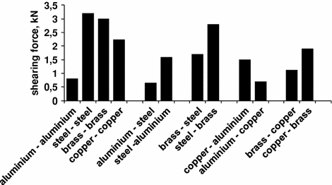
Typical clinch joint shearing strengths obtained for different materials
-
Material thickness—when the total sheet thickness increases, the strength of the clinch joint increases too, for the same tool combination.
-
Clinch point size—as in other mechanical joining methods, a larger diameter of a clinch joint involves a greater joint strength. This relation determined by the TOX® PRESSOTECHNIK for the TOX® Round Joint is shown in Fig. 15 as a common graph and table.
Fig. 15 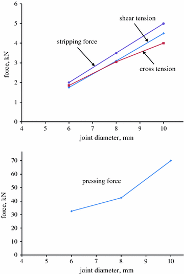
Medium values of clinch joint strength (steel St12/St14)—based on TOX® catalog date
-
Material surface condition—the material surface condition has influence on the clinch joint strength; a dry surface should give a stronger joint than an oiled or greased one, however, in steel these effects are relatively minor while they have considerable influence in aluminum.


The clinch joint strength is determined by the neck-thickness N1 and the undercut u, as illustrated in Fig. 5. Small undercuts lead to small joint strength because of the weak interlocking of the two sheets resulting in the separation of the upper sheet and the lower sheet. A thin neck causes the upper sheet in the neck to fracture. To increase the strength of the mechanical clinched joint, it is important to increase the undercut as well as the neck-thickness of the upper sheet.
In the case of clinch–adhesive joints the strength of the joint additionally depends on the adhesive interface structure (Fig. 9). Due to the squeezing of the joined materials just under the punch, the sheets flow in a radial direction and one can notice the varying thickness of the adhesive interface in the cross section, Fig. 3a. A local adhesive concentration takes place in the gorge of the joint, due to insufficient fulfillment of the die groove. This poses an additional difficulty in the formulation of the numerical model.
Experiments concerning the estimation of clinched and clinch–adhesive joints were described by Moroni et al. [19] and Balawender et al. [17].
In the first paper, the most advanced investigations concerning hybrid joints were carried out for specimens with substrates made of aluminium alloy (AA5052) and galvanized steel (S 275). The adhesive was Terokal 5077, a one component heat curing toughened epoxy adhesive. The tests were performed with an INSTRON 100 kN electro-mechanical testing machine with a crosshead speed of 2 mm/min. Additionally the effects of:
-
temperature influence from −30°C to 90°C and
-
ageing treatment by the salt spray
were investigated. The experimental analysis was conducted using the Design of Experiment (DoE) methodology in order to assess the influence of the material, geometrical factors and environment on static strength stiffness and energy absorption.
General conclusions from these investigations can be summarised as follows:
-
The strength of the hybrid joints is determined essentially by the adhesive.
-
The stiffness of hybrid joints is generally higher than that of simple joints by about 3–10% at room temperature. The loss of stiffness of the adhesive under high temperatures (90°C) is counterbalanced by clinching in the hybrid joint.
-
The ageing effects on the strength of bonded joints are caused by the reduction of the adhesive strength. The hybrid joints including the mechanical interlock by clinching significantly reduce the effect of ageing at high temperatures, i.e. are less sensitive to a temperature rise.
-
Hybrid joints have higher energy absorption than both simple bonded and mechanically fastened joints. Ageing substantially decreases energy absorption due to the brittle behaviour of the adhesive below its glass transition temperature. In the clinch-bonded joints, when the adhesive fails (after the peak load) the mechanical fastening continues to carry load, allowing a significant energy absorption increase.
Other types of materials for hybrid clinch–adhesive specimens were analysed by Balawender et al. [17]. Three sheet materials were used in the study: ETP-cooper, CuZn37 brass and low-carbon steel. Thickness of all sheets was 1 mm. The mechanical properties of the sheet materials were determined in uniaxial tensile tests and are collected in Table 1. The adhesive used in the tests was Dragon® (Chemical Factory DRAGON, Cracow, Poland), a two-component epoxy used for metal joining. The curing cycle of adhesive is 4 h at 20°C and it can be accelerated by warming up to 120°C. The full strength of the joints was obtained after 24 h.
The clinched lap joints were manufactured by a die and a punch arranged in a stamping attachment set on a 120 kN C-frame hydraulic press. The maximal press load was reduced by the overflow valve of the hydraulic system to about 90 kN. The geometry of the clinch tools is shown in Fig. 16. The tools were designed for joining two 1 mm thickness sheets. The position of the round indentation was symmetrical with respect to the specimen axis. The nominal diameter of the clinch bulging measured on the side of the die was equal 10 mm.

Clinching tools geometry
The maximal resistance to a shearing force was obtained when steel–steel sheets were joined and minimal for brass–brass sheets, Fig. 17.

Experimental load–displacement curves obtained for clinched joints
The hybrid joints were prepared with the application of the variant 3 of operations (Sect. 4) during manufacturing. The average value of the adhesive layer was equal to about 0.15 mm. The clinch joint parameters: X, th and u as well as a longitudinal section view of a hybrid single lap joint are shown in Table 2. As it can be seen, the parameters are comparable for steel–brass, brass–copper and steel–copper overlap. Differences between the clinch joint and the hybrid joint are visible in the bottom corner of the joint cavity as a fold; the adhesive caused a buckling of the lower material in the die groove. There is no difference in the shape of the upper material, which has been deformed by the punch; it is comparable with the one in the clinch joint without adhesive. The effect of this buckling on the shearing strength of hybrid lap joint can be negative.
The strength characteristics of hybrid joints compared with those of clinched joints are shown in Figs. 18, 19, 20, 21 and 22. Materials which create a strong clinched joint, i.e. steel–steel and steel–copper, do not create a hybrid joint with a high response to the shearing force. But strength characteristics of these materials have a special feature—when adhesive bonding joint fails, the clinching joint still keeps the materials connected, which results in high elongations (Figs. 18 and 19). When the shearing strength of clinched joint decreases (in relation to steel–steel joint), the strength of hybrid joint increases (Figs. 20, 21 and 22) and the clinch joint failure, observed as a step in the strength characteristic, is not so distinct (in case of brass–brass joint, it is not visible at all).

Experimental load–displacement curves (clinched and hybrid) obtained for steel–steel joints

Experimental load–displacement curves (clinched and hybrid) obtained for steel–copper joints

Experimental load–displacement curves (clinched and hybrid) obtained for brass–copper joints

Experimental load–displacement curves (clinched and hybrid) obtained for copper–copper joints

Experimental load–displacement curves (clinched and hybrid) obtained for brass–brass joints
Figure 23 shows a hybrid specimen made of steel and copper with an adhesive layer. The mode of failure is typical, i.e. the part of the softer material is subjected to bending. On the fracture surfaces, the adhesive layer remains adhered mainly on the steel, which means that the shear strength of the adhesive used in this experiment is much higher in comparison with the copper sheet yield stress. Only in the region of the clinching and the corners of the overlap joint area fragments of the adhesive remain on the surface of the copper sheet.

Failure modes of clinch–adhesive steel–copper joints
Table 3 gives of the energy absorption (EA) of all considered types of joints. With the application of the adhesive, the EA of hybrid joints manufactured from steel or steel–copper increase EA about 4.5 times in relation to pure clinching. It is interesting to notice that this increase up to the maximum peak of the force–displacement diagram is equal to 2.5–3 times. In the case of the copper–copper, brass–copper and brass–brass joints, almost the whole energy accumulation takes place up to the force maximum. The addition of the adhesive to the copper–copper joint is the most effective way to increase EA. Pure clinch joints made of brass and brass–copper are very weak when it comes to EA accumulation. Introduction of the adhesive layer diametrically changes the mechanical performance of these joints. It is particularly visible in the case of the brass–brass joints, where the increase of EA is approximately 20 times. To conclude the analysis of the EA parameter for the joints efficiency, one can state that the most effective application of the adhesive is in the case of the copper–copper and brass–brass joints.
6 Types of Failures
Typical failure modes of clinch joints under the tensile–shear (Figs. 11b and 13) are presented in Fig. 24 (e.g. [3, 4]). In the first mode, the thickness of the neck N1 (Fig. 12) is too small and the loading results in the failure of the neck. Such a situation takes place because of wrong production technology, i.e. the tools diameter is too small or the die is too deep. This leads to the formation of a long region of the joint neck and further to a crack nucleation. In the second mode, the loaded joint opens as a press-stud fastener. This is due to an excessive value of the parameter X, i.e. insufficient deformation during clinching produces a minor “S” shape interlocking (Fig. 9) and this leads to the second mode of failure. The third mode of failure is a combination of the two previous ones. In this mode, one edge of the joint fails and the other is deformed as in the first stage. This is because of local non-homogeneity of the clinch dimension and the internal material structure during the manufacturing process which can create local incisions or crevices (Fig. 10).

Failure modes of clinch joints: a neck fracture mode, b press-stud fastener mode (button separation)
Our experimental investigations indicate that some more failure modes under tensile–shear (Figs. 11b and 13) can be observed, Fig. 25:

Experimentally observed failure modes for different types of clinch joints: a joint of brass sheets, b joint of copper sheets, c joint of aluminum sheets, d joint of deep-drawing steel sheets, e joint of copper–aluminum sheets, f joint of steel–aluminum sheets
-
a mode shown in Fig. 25a occurs when the clinch joint is deformed and proceeds with a small deformation of the sheets. It is the result of an excessive bottom thickness X which produces small interlocking of the sheets (the undercut u is small)
-
in the failure mode illustrated in Fig. 25b, there is insufficient material in the neck of the joint, and loading results in cracks of this region. There are two reasons for this type of failure: the clearance of tool diameters is too small or the die is too deep. This leads to an excessive elongation in the region of the joint neck and causes a crack formation
-
the failure mode shown in Fig. 25c occurs when the sheets are folded in the punch side bottom. It is the result of small thickness of the clinch joint bottom X and takes place when joining materials exhibit high ductility, e.g. aluminum sheets
-
the mode presented in Fig. 25d corresponds to the case when bending of sheets is observed. This occurs when a good quality clinch joint made of deep-drawing steel sheets is subjected to shear
-
the last two modes of clinch joint failure are shown in Fig. 25e, f. This failure occurs when joining materials have different plastic properties, i.e. when the “strong” material is on the punch side and the weak one on the die side.
Lee et al. [6, 7] considered only the axial strength and pointed out two typical joint failure modes, i.e. the neck fracture mode and the press-stud fastener separation mode, Fig. 24. The neck fracture mode occurs as fracture of the upper sheet is the result of the thin neck; this fracture mode is very similar to the one of a tensile test (Fig. 25b). The press-stud fastener separation mode occurs when insufficient geometrical interlocking is performed during the clinching process and it is observed as the separation of the upper sheet and the lower sheet without fracture. This failure is similar to the one shown in Fig. 25a.
Figure 26 presents failure modes under tensile–shear of hybrid joints with a brittle adhesive. They are very similar to the corresponding simple clinching joints. All joints were opened in the press-stud process. However, the most important part is the sheets sequence during clinching. In case of clinching from the steel side (Fig. 26a), both joined sheets remain almost straight after the failure. The other situation takes place when the clinching process is from the copper side. Then bending of the copper side is observed.

Experimentally observed failure modes for different types of hybrid clinch–adhesive joints: a joint of deep-drawing steel–copper sheets (clinching from the steel side), b joint of deep-drawing steel–copper sheets (clinching from the copper side), c joint of deep-drawing steel sheets, d joint of copper sheets
It is important to point out that during the clinching process the following initial defects can occur:
-
large necking of the upper sheet on the side wall surface on the punch side (Fig. 27a)
Fig. 27 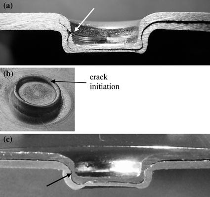
The most often defects in the clinching process: a necking of upper sheet leading to crack formation, b cracks on the die side of clinch joint of aluminum–copper, c no interlocking of upper sheet (sheet materials: copper–steel)
-
crack on the corner of the die projection (Fig. 27b)
-
no interlocking due to no flaring of the upper sheet in the lower sheet (Fig. 27c).

All these initial local discontinuities strongly influence the failure processes of clinched joints. The optimisation of the technology by the analysis of the crucial process parameters would therefore lead (Fig. 12) to the production of ideal joints without initial defects.
7 Examples of Use
Applications of the clinch joining process in manufacturing industry date back to about 25 years ago. The world’s leaders in this technology are TOX® PRESSOTECHNIK GMBH (TOX® PRESSOTECHNIK GmbH & Co. KG, Weingarten, Germany), ATTEXOR, Inc., Böllhoff Group (Wilhelm Böllhoff GmbH & Co. KG, Bielefeld, Germany) and others. The main industrial domains in which clinching is used, are:
-
automotive industry: front and rear bonnets, doors, wings, air bags, seat frames, pedals, air conditioners, etc. (Fig. 28),
Fig. 28 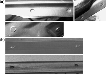
Examples of use of the clinching technique—clinch joints in: a automobile engine lid, b ventilating duct panel
-
electric and electronic equipment: computer housings, cable housings, contactors, etc.,
-
building: door and window frames, floor and roof elements, elevators ventilation, etc.,
-
household equipment: refrigerators, washing machines, micro-wave ovens, etc.,
-
and others.

Hybrid clinch–adhesive joining is a very modern assembly technology and it is not used in practise nowadays. This technology is being intensively investigated because of the expected advantages including low costs, flexibility and its environmental compatibility. The low mechanical strength of simple clinched joints (resistance to shear or tensile loading) compared to equivalent spot welds, forces to search for new joining solutions. Clinch–adhesive joining seems to be a very good combination which can enhance the advantages of both methods.
8 Conclusions and Future Trends
The clinch–adhesive technique may be useful for applications in the automotive, aeronautical and aerospace industry.
The mechanical strength of hybrid clinch–adhesive joints strongly depends on the adhesive and adherends’ properties. When joined materials undergo finite plastic deformation, adhesive properties should match these conditions. The adhesive Dragon® used in the tests described in this chapter is a brittle and stiff adhesive. The adhesive layer did not therefore sustain plastic deformation during the clinching process and adhesive failure occurred around the clinching indentation. This additionally demonstrates the influence of the processing technology—in the variant 3 (described in page 11) when the clinching process is the last one—on the initial microdamage introduced to the adhesive interface by clinching. Local microdamage entails a decrease in the shear strength of the tested hybrid joints. The proper production of hybrid joints (Sect. 4) is therefore a crucial point for further engineering applications.
The introduction of adhesives into clinching joints essentially changes the mechanical strength. It was confirmed by experimental and numerical simulation results [17, 19]. But taking into account the wide range of commercial adhesives for professional usage (from stiff and strong to flexible and ductile) the adhesive choice should be carefully balanced. The choice criterion of adhesive for the hybrid clinch–adhesive joint seems to be similar to the one of a mixed adhesive joint. The clinch joint is like a strong adhesive in the middle of the overlap and a flexible adhesive should be used in the neighbourhood. Future investigations should focus on the determination of such joint compositions such as a clinch-flexible adhesive.
The clinch–adhesive joints with a single adhesive or a combination of several adhesives might be useful for the aeronautical industry. However, they should bear temperatures from −55 to +200°C and dynamic loading. More attention should be focused on fatigue testing, including environmental corrosion and ageing problems. Low impact and high impact tests are important for total characterisation of the presented hybrid joints. Future experimental and numerical investigations are necessary.
References
Barnes, T.A., Pashby, I.R.: Joining techniques for aluminium spaceframes used in automobiles. Part II—adhesive bonding and mechanical fasteners. J. Mater. Proc. Technol. 99, 72–79 (2000)
Liebig, H.P., Bober, J., Beyer, R.: Connecting sheet metal by press joining. Bänder Bleche Rohre 25(9), 7 (1984). Vogel-Verlag, Würzburg
Varis, J.: Ensuring the integrity in clinching process. J. Mater. Proc. Technol. 174, 277–285 (2006)
Varis, J.P., Lepistö, J.: A simple testing-based procedure and simulation of the clinching process using finite element analysis for establishing clinching parameters. Thin Walled Struct. 41, 691–709 (2003)
Jayasekara, V., Min, K.H., Noh, J.H., Kim, M.T., Seo, J.M., Lee, H.Y., Hwang, B.B.: Rigid-plastic and elastic–plastic finite element analysis on the clinching joint process of thin metal sheets. Met. Mater. Int. 16, 339–347 (2010)
Lee, Ch.J., Kim, J.Y., Lee, S.K., Ko, D.Ch., Kim, B.M.: Design of mechanical clinching tools for joining of aluminium alloy sheets. Mat. Design 31, 1854–1861 (2010)
Lee, Ch.J., Kim, J.Y., Lee, S.K., Ko, D.Ch., Kim, B.M.: Parametric study on mechanical clinching process for joining aluminium alloy and high-strength steel sheets. J. Mech. Sci. Technol. 24, 123–126 (2010)
Nong, N., Keju, O., Yu, Z., Zhiyuan, Q., Changcheng, T., Feipeng, L.: Research on press joining technology for automotive metallic sheets. J. Mater. Proc. Technol. 137, 159–163 (2003)
Oudjene, M., Ben-Ayed, L.: On the parametrical study of clinching joining of metallic sheets using the Taguchi method. Eng. Struct. 30, 1782–1788 (2008)
Oudjene, M., Ben-Ayed, L.: Shape optimization of clinching tools using the response surface methodology with Moving Least-Square approximation. J. Mater Proc Technol. 209, 289–296 (2009)
da Silva, L.F.M., Adams, R.D.: Measurement of the mechanical properties of structural adhesives in tension and shear over a wide range of temperatures. J. Adhes. Sci. Technol. 19, 109–142 (2005)
Hergenrother, P.M.: Development of composites, adhesives and sealants for high-speed commercial airplanes. SAMPE J. 36, 30–41 (2000)
da Silva, L.F.M., Adams, R.D.: Techniques to reduce the peel stresses in adhesive joints with composites. Int. J. Adhes. Adhes. 27, 227–235 (2007)
Srinivas, S.: Analysis of bonded joints. NASA TN D-7855 (1975)
Geiss, P.L., Koetter, M.P., Presser, M., Raudonat, D.: Hybrid joining with pressure sensitive adhesives. http://www.pstc.org/files/public/TeCH33Papers/ (2010)
Brockmann, W., Geiss, P.L., Klingen, J., Schroeder, B.: Adhesive bonding—materials, applications and technology. Wiley-VCH, Weinheim (2008)
Balawender, T., Sadowski, T., Golewski, P.: Experimental and numerical analysis of hybrid: clinched–adhesive joint. In: ACE-X conference, Paris 8–9 July 2010
Abe, Y., Matsuda, A., Kato, T., Mori, K.: Plastic joining of aluminum alloy and high strength steel sheets by mechanical clinching. Met. Form. 1, 649–656 (2008)
Moroni, F., Pirondi, A., Kleiner, F.: Experimental analysis and comparison of the strength of simple and hybrid structural joints. Int. J. Adhes. Adhes. 30, 367–379 (2010)
Abe, Y., Kishimoto, M., Kato, T., Mori, K.: Joining of hot-dip coated steel sheets by mechanical clinching. Int. J. Mater. Form. 2(Suppl 1), 291–294 (2009)
Carboni, M., Beretta, S., Monno, M.: Fatigue behaviour of tensile–shear loaded clinch joints. Eng. Fract. Mech. 73, 178–190 (2006)
de Paula, A.A., Aguilar, M.T.P., Pertence, A.E.M., Cetlin, P.R.: Finite element simulations of the clinch joining of metallic sheets. J. Mater. Proc. Technol. 182, 352–357 (2007)
He, X.: Recent development in finite element analysis of clinched joints. Int. J. Adv. Manuf. Technol. 48, 607–612 (2010)
Saberi, S., Enzinger, N., Vallant, R., Cerjak, H., Hinterdorfer, J., Rauch, R.: Influence of plastic anisotropy on the mechanical behaviour of clinched joint of different coated thin steel sheets. Int. J. Mater. Form. 1(Suppl. 1), 273–276 (2008)
Varis, J.P.: The suitability of clinching as a joining method for high-strength structural steel. J. Mater. Proc. Technol. 132, 242–249 (2003)
Acknowledgement
The research leading to these results has received funding from:
Financial support of Structural Funds in the Operational Programme—Innovative Economy (IE OP) financed from the European Regional Development Fund—Project “Modern material technologies in aerospace industry”, No. POIG.0101.02-00-015/08 is gratefully acknowledged (RT-15: Unconventional technologies of joining elements of aeronautical constructions),The European Union Seventh Framework Programme (FP7/2007–2013), FP7-REGPOT-2009-1, under grant agreement No. 245479.
Author information
Authors and Affiliations
Corresponding author
Editor information
Editors and Affiliations
Rights and permissions
Copyright information
© 2010 Springer-Verlag Berlin Heidelberg
About this chapter
Cite this chapter
Sadowski, T., Balawender, T. (2010). Technology of Clinch–Adhesive Joints. In: da Silva, L., Pirondi, A., Öchsner, A. (eds) Hybrid Adhesive Joints. Advanced Structured Materials, vol 6. Springer, Berlin, Heidelberg. https://doi.org/10.1007/8611_2010_45
Download citation
DOI: https://doi.org/10.1007/8611_2010_45
Published:
Publisher Name: Springer, Berlin, Heidelberg
Print ISBN: 978-3-642-16622-8
Online ISBN: 978-3-642-16623-5
eBook Packages: Chemistry and Materials ScienceChemistry and Material Science (R0)