
Abstract
So far, we have studied growth of a crack only for the case when the load is applied normal to the crack and such that the crack propagates in a self-similar manner.
Access this chapter
Tax calculation will be finalised at checkout
Purchases are for personal use only
References
Sih GC (1973) Some basic problems in fracture mechanics and new concepts. Eng Fract Mech 5:365–377
Sih GC (1973) Energy-density concept in fracture mechanics. Eng Fract Mech 5:1037–1040
Sih GC (1974) Strain-energy-density factor applied to mixed-mode crack problems. Int J Fract 10:305–321
Sih GC (1973) A special theory of crack propagation: methods of analysis and solutions of crack problems. In: Sih GC (ed) Mechanics of Fracture, vol 1. Noordhoff Int. PubI., The Netherlands, pp XXI–XLV
Sih GC (1975) A three-dimensional strain energy density factor theory of crack propagation. In: Kassir MK, Sih GC (eds) Mechanics of fracture, vol 2. Noordhoff Int. Publ., The Netherlands, pp XV–LIII
Sih GC (1977) Strain energy density theory applied to plate bending problems. In: Sih GC (ed) Mechanics of fracture, vol 3. Noordhoff Int. Publ., The Netherlands, pp XVII–XLVIII
Sih GC (1977) Dynamic crack problems-strain energy density fracture theory. In: Sih GC (ed) Mechanics of fracture, vol 4. Noordhoff Int. Publ., The Netherlands, pp XVII–XLVII
Sih GC (1978) Strain energy density and surface layer energy for blunt cracks or notches. In: Sih GC (ed) Mechanics of fracture, vol 5. Noordhoff Int. Publ., The Netherlands, pp XIII–CX
Sih GC (1981) Failure of composites as predicted by the strain energy density theory. In: Sih GC, Chen EP(eds) Mechanics of fracture, vol 6. Martinus Nijhoff Publ., pp XV–LXXXI
Sih GC (1981) Experimental fracture mechanics: strain energy density criterion. In: Sih GC (ed) Mechanics of fracture, vol 7. Martinus Nijhoff Publ., pp XVII–LVI
Gdoutos EE (1984) Problems of mixed mode crack propagation. Martinus Nijhoff PubI
Hoek E, Bieniawski ZT (1965) Fracture propagation mechanics in hard rock. Technical Report-Rock Mechanics Division, South African Council for Scientific and Industrial Research
Sih GC, Kiefer BV (1979) Nonlinear response of solids due to crack growth and plastic deformation. In: Perrone N, Atluri SW (eds) Nonlinear and dynamic fracture mechanics, vol 35. The American Society of Mechanical Engineers, AMD, pp 136–156
Sih GC, Chen C (1985) Non-self-similar crack growth in elastic-plastic finite thickness plate. Theoret Appl Fract Mech 3:125–139
Erdogan F, Sih GC (1963) On the crack extension in plates under plane loading and transverse shear. J Basic Eng Trans ASME 85D:519–527
Author information
Authors and Affiliations
Corresponding author
Appendices
Examples
Example 7.1
According to the maximum dilatational strain energy density criterion , the crack extends along the direction of maximum dilatational strain energy density which is calculated around the circumference of a circular core area surrounding the crack tip. Derive an equation to determine the crack extension angle in a two-dimensional mixed-mode stress field governed by the KI and KII stress intensity factors under conditions of plane strain. Apply this equation to an inclined crack in an infinite plate subjected to a uniform uniaxial stress at infinity, and compare the crack growth angles with those obtained by the strain energy density and the stress criteria.
Solution
For linear elastic deformation, the strain energy density, \( ({\text{d}}W/{\text{d}}V) \), can be decomposed into its dilatational, \( ({\text{d}}W/{\text{d}}V)_{\nu } \), and distortional, \( ({\text{d}}W/{\text{d}}V)_{d} \), components as a sum
The strain energy density \( ({\text{d}}W/{\text{d}}V) \) is given by Eqs. (7.9), (7.14) and (7.15), while the dilatational and distortional strain energy density components are computed from Eqs. (7.5), (7.6) and (7.13). Under conditions of plane strain we obtain the dilatational part
such that
and for the distortional part
such that
where \( \mu \) is the shear modulus and r the radial distance from the crack tip.
According to the maximum dilatational strain energy density assumption, the angle \( \theta_{c} \) of initial crack extension can be obtained as
Equation (6) gives
Equation (7) determines the angle \( \theta_{c} \) when the values of stress intensity factors kI and kII are known.
For an inclined crack in an infinite plate the values of KI and KII are given by Eq. (7.17). Substituting these values into Eq. (7), we find the crack extension angle \( \theta_{c} \) to be
Equation (8) for \( 0 < \beta < \pi /2 \) predicts angles \( \theta_{c} \) in the range \( - \pi < \theta_{c} < 0 \), while according to the strain energy density and stress criteria which are verified by experimental results the angle \( \theta_{c} \) varies in the interval \( - \pi /2 < \theta_{c} < 0 \). Thus the maximum dilatational strain energy density criterion leads to predictions which are unrealistic and far beyond any experimental observation.
Example 7.2
An infinite plate contains a circular crack of radius R and angle \( 2\beta \) and is subjected to a uniform uniaxial tensile stress \( \sigma \) at infinity perpendicular to the chord of the crack. The stress intensity factors kI and kII at the crack tip are given by
Plot the variation of the angle of crack extension \( \theta_{c} \), and the critical stress \( \sigma_{c} \) for crack growth, versus the angle of the crack \( 2\beta \), for various values of \( \kappa \) (\( \kappa = 3 - 4\nu \) for plane strain and \( \kappa = (3 - \nu )/(1 + \nu ) \) for plane stress).
Solution
Substituting the values of stress intensity factors kI and kII from Eq. (1a, 1b) into Eq. (7.16a) of the strain energy density criterion we obtain an equation containing the quantities \( \beta \), \( \kappa \) and \( \theta \). The roots of this equation which satisfy inequality (7.16b) give the values of the crack extension angle \( \theta_{c} \). The critical stress \( \sigma_{c} \) for initiation of crack extension is then determined from Eqs. (7.12), (7.14) and (7.15), where Sc is a material parameter.
Figure 7.14 presents the variation of \( - \theta_{c} \) versus the half angle of the circular crack \( \beta \) for the extreme values of \( \kappa \) equal to 1.0 and 3.0. The figure also shows the straight line \( - \theta_{1} = \beta \) corresponding to extension of the crack at a right angle to the direction of the applied load. We see that the angle \( - \theta_{1} \) increases monotonically with \( \beta \), and that, in the interval \( 0^{ \circ } < \beta < 137.5^{ \circ } \), the angles \( - \theta_{1} \) for \( \kappa = 1.0 \) are always greater than those for \( \kappa = 3.0 \). This rule is reversed in the interval \( 137.5^{ \circ } < \beta < 180^{ \circ } \). Furthermore, Fig. 7.14 illustrates that initial crack extension takes place in a direction almost normal to the applied load for all values of \( \beta \) in the interval \( 0 < \beta < 120^{ \circ } \). When the angle \( \beta \) is greater than 120° the direction of crack extension deviates from that normal to the load, becoming parallel to the applied load for \( \beta = 180^{ \circ } \). The values of the quantity \( \sigma_{c} \left( {R/16\mu S_{c} } \right)^{1/2} \) for \( \kappa = 1.0 \), 1.4 and 3.0 are presented in Fig. 7.15. It can be seen that all curves for the values of the angle \( \beta \) equal to \( \beta = 0^{ \circ } \), 180° and 137.5° tend to infinity. We conclude that a plate weakened by a circular crack requires an infinitely large stress for crack extension, not only for the trivial case of zero angle circular crack, but also for the values of \( 2\beta = 275^{ \circ } \) and 360°. The infinite value of stress for crack extension is given by the linear theory of fracture. Its physical meaning is that failure of the cracked plate takes place at the same critical load as failure of the uncracked plate. We further observe that the critical stress for crack extension decreases as \( \kappa \) increases, or as the Poisson’s ratio \( \nu \) decreases. We also see that, for each value of \( \kappa \), there is a specific value of the angle of crack \( 2\beta \) at which the required stress for crack extension reaches a minimum. This critical value of the angle \( 2\beta \) is equal to 85°, 115° and 140° for \( \kappa = 3.0 \), 1.4 and 1.0 respectively.

Crack extension angle \( \left( { - \theta_{c} } \right) \) versus half angle \( \beta \) of a circular crack whose chord is perpendicular to the applied tensile stress for \( \kappa = 1.0 \) and 3.0. The straight dotted line corresponds to the extension of the crack at right angle to the direction of the applied load

Normalized critical stress for crack extension versus half angle \( \beta \) of a circular crack whose chord is perpendicular to the applied tensile stress for \( \kappa = 1.0 \), 1.4 and 3.0
Example 7.3
For the cylindrical pressure vessel of Example 2.5 determine the angle of initial crack extension \( \theta_{c} \) and the critical internal pressure \( p_{c} \) for initiation of crack growth for various values of the crack angle \( \beta \). Take \( \nu = 0.25 \).
Solution
Substituting the values of stress intensity factors KI and KII obtained in Example 2.5 into Eq. (7.14) we obtain the strain energy density factor
where
The coefficients \( a_{ij} \) are given by Eq. (7.15).
According to the SED criterion, the angle of initial crack extension \( \theta_{c} \) is determined from Eq. (7.11). Values of \( - \theta_{c} \) for various crack inclination angles \( \beta \) are shown in Table 7.2.
Substituting the values of \( \theta_{c} \) into Eq. (1) and equating the resulting value of S to Sc we obtain the critical internal pressure pc as
Values of the dimensionless quantity \( p_{c} R\sqrt a /2t \) for different angles \( \beta \) are shown in Table 7.3.
Observe from this table that a longitudinal crack \( \left( {\beta = 90^{ \circ } } \right) \) is more dangerous than a circumferential crack \( \left( {\beta = 0} \right) \) of the same length.
Example 7.4
A cylindrical bar of radius b contains a circular crack of radius a and is subjected to a force P along the axis of the bar and a torque T (Fig. 7.16). The opening-mode and tearing-mode stress intensity factors kI and kIII along the crack front created by the force P and torque T, respectively, are given by

Fracture loci of a cylindrical bar with an internal crack subjected to tension and torsion
where
For a bar with a0 = 0.016 cm, b = 2.0 cm and v = 1/3 subjected to the force P only the critical stress for fracture is \( \sigma_{u} \). Determine the fracture loci when the bar is subjected to both force P and torque T for a/b = 0.008, 0.012 and 0.018.
Solution
The strain energy density function dW/dV for tearing-mode deformation is obtained by substituting the values of stresses τxz and τyz from Eq. (2.56) into Eq. (7.2). We obtain
The strain energy density factor S is computed from Eqs. (3) and (7.9) as
The strain energy density factor S for a combination of opening-mode and tearing-mode is therefore given by
where the coefficient a11 is given by Eq. (7.15) with \( \kappa = 3 - 4\nu \).
The angle of crack growth \( \theta_{c} \) is determined from Eq. (7.11) as \( \theta_{c} = 0 \), that is the crack grows in its own plane.
Equation (7.12) of the strain energy density criterion gives
\( K_{{{\text{I}}c}} \) is calculated from the fracture stress \( \sigma_{u} \) of a bar of radius b = 2.0 cm with a crack of radius ao = 0.016 cm as
and Sc is computed from Eq. (7.26) as
When the value of Sc is introduced into Eq. (6) we obtain
Equation (9) presents the required relation between \( \sigma \) and \( \tau \) for fracture of the bar (fracture locus). Figure 7.16 shows the fracture loci for a/b = 0.008, 0.012 and 0.018 when a0 = 0.016 cm, b = 2.0 cm, v = 1/3. For all combinations of \( \sigma \) and \( \tau \) that lie outside the curves, fracture of the bar takes place by unstable growth of the circular crack, while for the remaining values of \( \sigma \) and \( \tau \) the crack does not propagate.
Example 7.5
An infinite elastic plate is perforated by a circular hole of radius R and a system of n symmetrically located small radial cracks of length l (Fig. 7.17). The plate is x-axis. The stress intensity factors \( k_{\text{I}}^{(j)} \) and \( k_{\text{II}}^{(j)} \) at the tip of the j crack are given by

An infinite plate perforated by a circular hole with an array of n small radial cracks subjected to an inclined tension \( \sigma \)
where
Determine the critical fracture stress \( \sigma_{c} \) of the plate that triggers unstable growth of one of the radial cracks.
Solution
The critical value \( \sigma_{c}^{\left( j \right)} \) of the applied stress \( \sigma \) for extension of the j-crack is obtained by using Eqs. (7.16a) and (7.16b) and (7.12) of the strain energy density criterion for the j-crack, with the values of the stress intensity factors \( k_{\text{I}}^{(j)} \) and \( k_{\text{II}}^{(j)} \) given by Eqs. (1) and (2). It is evident that brittle failure of the plate will take place from the extension of the crack which requires the lowest critical stress \( \sigma_{c}^{\left( j \right)} \). Therefore, the critical value \( \sigma_{c} \) of the applied stress for failure of the plate is given by
Figure 7.18 presents the variation of the dimensionless critical stress \( \sigma_{c} \left( {R/32\mu S_{c} } \right)^{ - 1/2} \) versus the angle \( \alpha \) of inclination of the applied stress with respect to the Ox-axis for a plate containing five (n = 5) radial cracks. The ratio \( \delta \) of crack length l to hole radius R takes the values \( \delta = 0.01 \) and 0.1. The material constant \( \kappa \) is equal to \( \kappa \) = 1.4, 1.8, 2.2 and 3.0. The dashed lines in the figure separate the regions in which fracture of the plate starts from unstable growth of the more vulnerable crack j = 0, 2 and 4. Values of the quantity \( \sigma_{c} \left( {R/32\mu S_{c} } \right)^{ - 1/2} \) for \( \alpha \) = 60°, \( \delta \) = 0.01, 0.04 and 0.1, \( \kappa \) = 1.4, 2.2 and 3.0 and various radial cracks (n = 1, 2, …, 20) are presented in Table 7.4.

Normalized critical stress for crack extension versus angle \( \alpha \) of inclination of the applied stress with respect to the x-axis of Fig. 7.17 with n = 5 and a \( \delta = 0.01 \) and b \( \delta = 0.1 \), for \( \kappa = 1.4 \), 1.8, 2.2 and 3.0
Example 7.6
-
(a)
A crack of length 2a in a large plate grows in a stable manner under a constant uniform uniaxial stress \( \sigma_{0} \) normal to the crack plane (Fig. 7.19a). Determine the crack growth increment \( r_{j} \,\,(j = 1,2, \ldots ,n) \) during stable crack growth.
Fig. 7.19 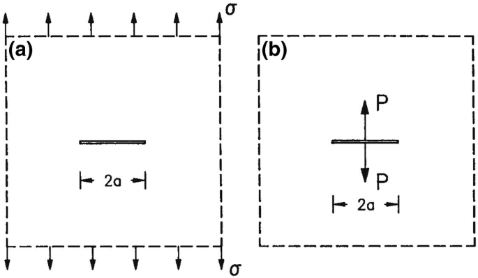
Cracked specimens for a unstable crack growth and b stable crack growth
-
(b)
As in the previous case for a crack of length 2a in an infinite plate subjected to wedge forces P at the middle of the crack (Fig. 2.19b).

Solution
-
(a)
Stable crack growth is dictated by Eq. (7.10) of the SED criterion.
In our case S is calculated from Eq. (7.24) as
Equation (7.10) becomes
or
If crack initiation starts when r1 = r0 the following recursion relation for incremental crack growth is obtained
Equation (4) indicates that each consecutive step of crack growth increases. Unstable crack growth occurs when rj reaches the critical ligament length rc·
-
(b)
For this case the stress intensity factor KI is given by (Example 2.2)
and the strain energy density factor S is computed from Eq. (7.14) with \( \theta = 0 \), as
When stable growth of the crack occurs under constant force P, Eq. (7.10) becomes
which for \( r_{1} = r_{0} \) gives
Equation (8) indicates that each consecutive step of crack growth decreases. Crack arrest occurs when rj reaches the critical ligament length rc.
Example 7.7
The stress intensity factors KI and KII at the right tip of the crack of Fig. 7.20 are given by

A crack in an infinite plate subjected to a uniform load on part of the upper crack surface
Calculate the angle \( \theta_{c} \) of extension of the crack from its right tip according to the maximum stress criterion. Take b/a = 0.5, c/a = 0.8, v = 0.3 and assume conditions of plane strain.
Solution
The angle \( \theta_{c} \) is calculated from Eq. (7.38) of the maximum stress criterion. This equation for \( \theta_{c} \ne \pi \), \( K_{\text{II}} = 0 \) becomes
We have
where for plane strain \( \kappa = 3 - 4\nu = 1.8 \).
Introducing the values of KI and KII from Eq. (3) into Eq. (2) we obtain the crack angle
Calculating \( \sigma_{\theta } \) for the two angles \( \theta_{c} \) from Eq. (7.35b) we find that it becomes maximum for \( \theta_{c} = - 14.14^{ \circ } \) and therefore this is the angle of extension of the crack from its right tip.
Problems
-
7.1.
The stress field in the neighborhood of a sharp elliptical notch in a mixed-mode stress field under conditions of plane strain is given by
$$ \begin{aligned} \sigma_{x} = & \frac{1}{{\sqrt {2r} }}\left[ {k_{1} \cos \frac{\theta }{2}\left( {1 - \sin \frac{\theta }{2}\sin \frac{3\theta }{2}} \right) - k_{1} \left( {\frac{\rho }{2r}} \right)\cos \frac{3\theta }{2}} \right. \\ & \quad \left. { - k_{2} \sin \frac{\theta }{2}\left( {2 + \cos \frac{\theta }{2}\cos \frac{3\theta }{2}} \right) + k_{2} \left( {\frac{\rho }{2r}} \right)\sin \frac{3\theta }{2}} \right] \\ \sigma_{y} = & \frac{1}{{\sqrt {2r} }}\left[ {k_{1} \cos \frac{\theta }{2}\left( {1 + \sin \frac{\theta }{2}\sin \frac{3\theta }{2}} \right) + k_{1} \left( {\frac{\rho }{2r}} \right)\cos \frac{3\theta }{2}} \right. \\ & \quad \left. { + k_{2} \sin (\frac{\theta }{2}) {\cos (\frac{\theta }{2})\cos (\frac{3\theta }{2})} - k_{2} \left( {\frac{\rho }{2r}} \right)\sin \frac{3\theta }{2}} \right] \\ \tau_{xy} = & \frac{1}{{\sqrt {2r} }}\left[ {k_{1} \sin \frac{\theta }{2}\cos \frac{\theta }{2}\cos \frac{3\theta }{2} - k_{1} \left( {\frac{\rho }{2r}} \right)\sin \frac{3\theta }{2}} \right. \\ & \quad \left. { + k_{2} \cos \frac{\theta }{2}\left( {1 - \sin \frac{\theta }{2}\sin \frac{3\theta }{2}} \right) - k_{2} \left( {\frac{\rho }{2r}} \right)\cos \frac{3\theta }{2}} \right] \\ \sigma_{z} = & \, \nu \left( {\sigma_{11} + \sigma_{22} } \right),\quad \tau_{yz} = \tau_{zx} = 0 \\ \end{aligned} $$where \( \rho \) is the notch radius. The radial distance r is measured from the focal point of the notch and the angle \( \theta \) is measured from a line extended from the major axis of the notch.
Show that the strain energy density factor S is given by
$$ S = r\frac{{{\text{d}}W}}{{{\text{d}}V}} = S_{1} + \frac{{S_{2} }}{r} + \frac{{S_{3} }}{{r^{2} }} $$where
$$ \begin{aligned} S_{1} = & \, a_{11} k_{1}^{2} + 2a_{12} k_{1} k_{2} + a_{22} k_{2}^{2} \\ S_{2} = & \, b_{11} k_{1}^{2} + 2b_{12} k_{1} k_{2} + b_{22} k_{2}^{2} \\ S_{3} = & \, c_{11} k_{1}^{2} + 2c_{12} k_{1} k_{2} + c_{22} k_{2}^{2} . \\ \end{aligned} $$The coefficients aij are given by Eq. (7.15), while bij and cij are given by
$$ \begin{aligned} b_{11} = & \, 0,\quad b_{12} = - \frac{\rho }{8\mu }\sin \;\theta ,\quad b_{22} = - \frac{\rho}{4\mu }\cos \;\theta \\ c_{11} = & \frac{{\rho^{2} }}{16\mu },\quad c_{12} = 0,\quad c_{22} = \frac{{\rho^{2} }}{16\mu }. \\ \end{aligned} $$ -
7.2.
Show that the critical in-plane shear stress \( \tau_{c} \) and the critical tensile stress \( \sigma_{c} \) to fracture an infinite plate with a crack of length 2a are related under conditions of plane strain by
$$ \frac{{\sigma_{c} }}{{\tau_{c} }} = \left[ {\frac{{2(1 - \nu ) - \nu^{2} }}{3(1 - 2\nu )}} \right]^{1/2} . $$ -
7.3.
Show that the critical in-plane shear stress \( \tau_{c} \) and the critical out-of-plane shear stress sc to fracture an infinite plate with a crack of length 2a are related under conditions of plane strain by
$$ \frac{{\tau_{c} }}{{s_{c} }} = \left[ {\frac{3}{{2(1 - \nu ) - \nu^{2} }}} \right]^{1/2} . $$ -
7.4.
Consider a crack of length 2a that makes an angle \( \beta \) with the y direction in an infinite plate subjected to stresses \( \sigma \) and \( k\sigma \) along the y and x directions, respectively, at infinity (Fig. 2.9a). Plot the variation of crack extension angle \( \theta_{c} \) and the critical stress \( \sigma_{c} \) for crack growth versus the crack inclination angle \( \beta \) for \( \kappa = 0.2 \), 0.6, −0.2 and −1.0 and \( \kappa = 1.0 \), 1.4, 1.8, 2.2, 2.6 and 3.0 when the stress \( \sigma \) is tensile.
-
7.5.
As in Problem 7.4 when the stress \( \sigma \) is compressive.
-
7.6.
An infinite plate contains a circular crack of radius R and angle \( 2\beta \) and is subjected to a uniform uniaxial tensile stress \( \sigma \) at infinity parallel to the chord of the crack (Fig. 7.21). The stress intensity factors kI and kII at the crack tip are given by
Fig. 7.21 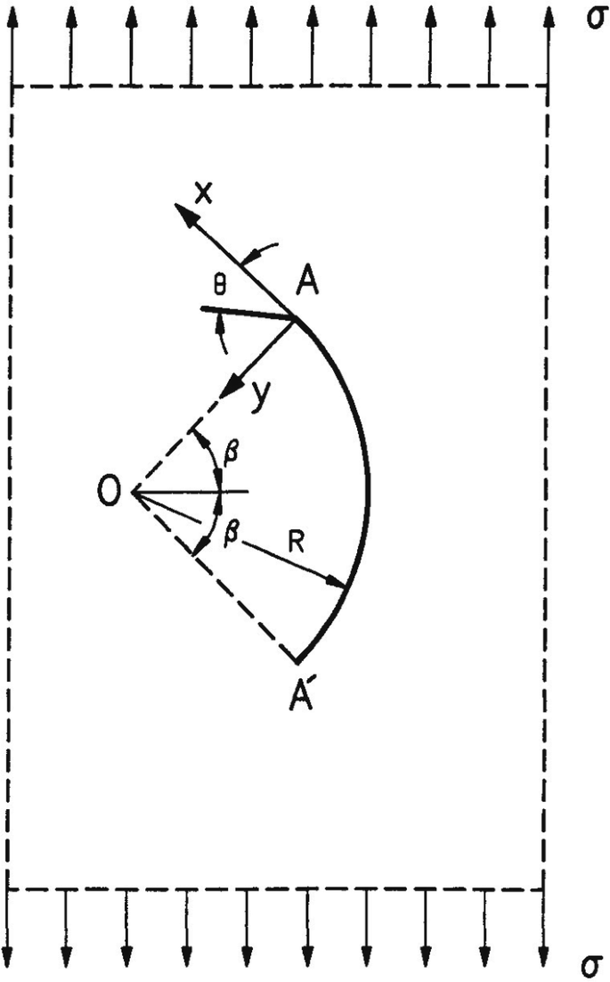
An infinite plate containing a circular crack with its chord parallel to the direction of applied uniaxial stress
$$ k_{\text{I}} = \frac{\sigma }{2}(R\;\sin \;\beta )^{1/2} \left[ {\frac{{\left( {1 + \sin^{2} \dfrac{\beta }{2}\cos^{2} \dfrac{\beta }{2}} \right)\cos \dfrac{\beta }{2}}}{{1 + \sin^{2} \dfrac{\beta }{2}}} - \cos \frac{3\beta }{2}} \right] $$$$ k_{\text{II}} = \frac{\sigma }{2}(R\;\sin \;\beta )^{1/2} \left[ {\frac{{\left( {1 + \sin^{2} \dfrac{\beta }{2}\cos^{2} \dfrac{\beta }{2}} \right)\sin \dfrac{\beta }{2}}}{{1 + \sin^{2} \dfrac{\beta }{2}}} - \sin \frac{3\beta }{2}} \right]. $$Plot the variation of the angle of crack extension \( \theta_{c} \) and the critical stress \( \sigma_{c} \) for crack growth versus the angle of the crack \( 2\beta \) for various values of \( \kappa \) (\( \kappa = 3 - 4\nu \) for plane strain and \( \kappa = \left( {3 - \nu } \right)/\left( {1 + \nu } \right) \) for plane stress).
-
7.7.
As in Problem 7.6 for compressive applied stress \( \sigma \).
-
7.8.
As in Example 7.2 for compressive applied stress \( \sigma \).
-
7.9.
A crack of length 2a in an infinite plate is subjected to a concentrated force P applied at the point x = b (Fig. 2.16a). The stress intensity factors at the crack tip B are given in Problem 2.5, while the stress intensity factors at the other crack tip A can be obtained from symmetry considerations as
$$ \begin{aligned} K_{{{\text{I}}A}} ( - a,b) = & K_{{{\text{I}}B}} (a, - b) \\ K_{{{\text{I}}A}} ( - a,b) = & - K_{{{\text{II}}B}} (a, - b). \\ \end{aligned} $$Show that the crack grows from its tip B, and plot the variation of crack extension angle \( \theta_{c} \) and critical stress of fracture \( \sigma_{\text{c}} \) versus b/a (0 < b/a < 1) for \( \kappa = 1.4 \), 1.8, 2.2 and 3.0, when the load P is tensile or compressive.
-
7.10.
A crack of length 2a in an infinite plate is subjected to a concentrated force Q applied at the point x = b (Fig. 2.16a). The stress intensity factors at the crack tip B are given in Problem 2.5, while the stress intensity factors at the other crack tip A can be obtained from symmetry considerations as
$$ \begin{aligned} K_{{{\text{I}}A}} ( - a,b) = & - K_{{{\text{I}}B}} (a, - b) \\ K_{{{\text{II}}A}} ( - a,b) = & K_{\text{II}} (a, - b). \\ \end{aligned} $$Plot the variation of the crack extension angle \( \theta_{c} \) and the critical stress of fracture \( \sigma_{c} \) versus b/a (0 < b/a < 1) for \( \kappa = 1.4 \), 1.8, 2.2 and 3.0. Indicate the regions where extension of the crack starts from its tip A or B.
-
7.11.
Show that the crack of Problem 2.34 propagates along its own plane which is titled at an angle \( \omega \) to the plane of loading. Show that the critical stress \( \sigma_{c} \) for crack growth is given by
$$ \sigma_{c} = \frac{{2\sqrt {\mu S_{c} } }}{{\sqrt a {\kern 1pt} \sin \;\omega \sqrt {1 - 2\nu \;\sin^{2} \omega } }}. $$Plot the variation of \( \sigma_{c} \sqrt a /2\sqrt {\mu S_{c} } \) versus \( \omega \) for v = 0, 0.1, 0.25, 0.33 and 0.5 and find the angle \( \omega_{c} \) at which \( \sigma_{c} \) becomes minimum for each value of v.
-
7.12.
A cylindrical vessel of radius R and thickness t contains a through crack of length 2a parallel to its axis (Fig. 7.22). The edges of the crack are inclined at an angle \( \upgamma \) with the surfaces of the vessel wall. The vessel is subjected to a torque T. Determine the crack growth direction and the critical moment Tc for initiation of crack growth. Plot the variation of Tc versus angle \( \upgamma \) for various values of Poisson’s ratio \( \nu \).
Fig. 7.22 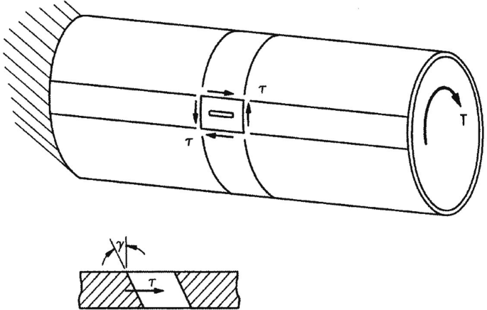
A cylindrical vessel with a through crack parallel to its axis whose edges are inclined with respect to the surface of the vessel wall
-
7.13.
A cylindrical bar of radius b contains a ring-shaped edge crack of depth a in a plane normal to its axis (Fig. 7.23). The bar is subjected to a force P along its axis and to a torque T. The opening-mode and tearing-mode stress intensity factors kI and kIII along the crack front created by the force P and torque T, respectively, are given by
Fig. 7.23 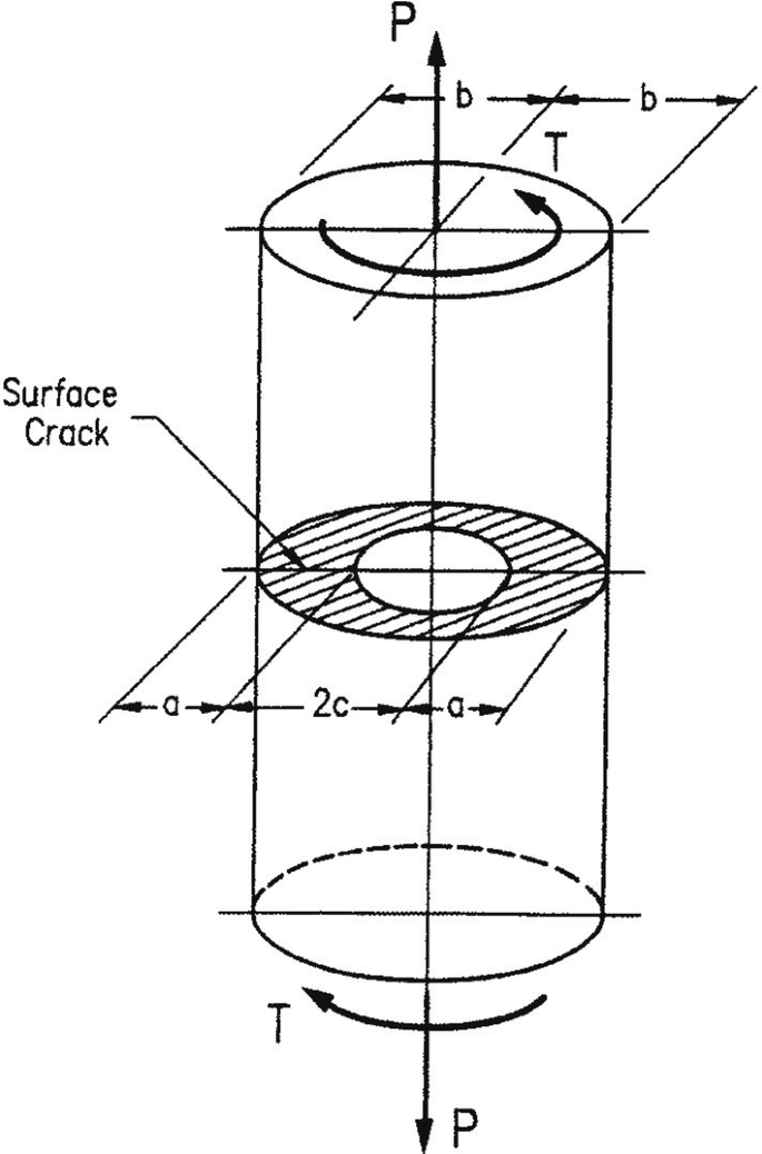
A cylindrical bar with an external crack subjected to tension and torsion
$$ k_{\text{I}} = \sigma \left( {\frac{b}{c}} \right)^{2} \sqrt {\frac{ac}{b}} g_{1} \left( {\frac{c}{b}} \right),\sigma = \frac{P}{{\pi b^{2} }} $$$$ k_{\text{III}} = \tau \left( {\frac{b}{c}} \right)^{3} \sqrt {\frac{ac}{b}} g_{3} \left( {\frac{c}{b}} \right),\;\tau = \frac{2Ta}{{\pi b^{4} }} $$where
$$ \begin{aligned} g_{1} \left( {\frac{c}{b}} \right) = & \frac{1}{2}\left[ {1 + \frac{1}{2}\frac{c}{b} + \frac{3}{8}\frac{{c^{2} }}{{b^{2} }} - 0.363\frac{{c^{3} }}{{b^{3} }} + 0.731\frac{{c^{4} }}{{b^{4} }}} \right] \\ g_{3} \left( {\frac{c}{b}} \right) = & \frac{3}{8}\left[ {1 + \frac{1}{2}\frac{c}{b} + \frac{3}{8}\frac{{c^{2} }}{{b^{2} }} + \frac{5}{16}\frac{{c^{3} }}{{b^{3} }} + \frac{25}{128}\frac{{c^{4} }}{{b^{4} }} + 0.208\frac{{c^{5} }}{{b^{5} }}} \right]. \\ \end{aligned} $$For a bar with a0 = 0.0052 cm, b = 2.0 cm and v = 1/3 subjected to the force P only, the critical stress for fracture is \( \sigma_{u} \). Determine the fracture loci when the bar is subjected to both force P and torque T for a/b = 0.003, 0.005 and 0.011.
-
7.14.
A large thick plate of steel contains a crack of length 5 mm oriented at an angle \( \beta = 30^{\circ } \) with respect to the direction of applied uniaxial tensile stress \( \sigma \). Calculate the value of the critical stress \( \sigma_{c} \) for crack growth. \( K_{{{\text{I}}c}} = 60\;{\text{MPa}}\sqrt {\text{m}} \), \( E = 210\;{\text{GPa}},\nu = 0.3 \).
-
7.15.
As in Problem 7.14 for compressive applied stress \( \sigma \).
-
7.16.
A cylindrical pressure vessel with closed ends has a radius R = 1 m and thickness t = 40 mm and it is subjected to internal pressure p. The vessel contains a through crack of length 4 mm oriented at an angle 40° with respect to the circumferential direction. Calculate the maximum pressure pc the vessel can withstand without failure. \( K_{{{\text{I}}c}} = 60\;{\text{MPa}}\sqrt {\text{m}} \), \( E = 210\;{\text{GPa}},\nu = 0.3 \).
-
7.17.
A large thick plate containing a crack of length 4 mm oriented at an angle β = 60° with respect to the direction of applied uniaxial tensile stress fractures at a value \( \sigma_{c} = 1000\;{\text{MPa}} \). Calculate \( K_{\text{Ic}} \) when E = 210 GPa, \( \nu = 0.3 \).
-
7.18.
A large thick plate of steel is subjected to a tensile stress \( \sigma = 800\;{\text{MPa}} \) oriented at an angle 50° with respect to the direction of a through crack. Calculate the maximum permissible crack length the plate can withstand without fracture. Sc = 1500 N/m, E = 210 GPa, v = 0.3.
-
7.19.
As in Problem 7.18 when the applied stress \( \sigma \) is compressive.
-
7.20.
A large thick plate contains a crack of length 2a oriented at an angle \( \beta \) with respect to the direction of applied uniaxial tensile stress \( \sigma \). Plot the variation of the quantity \( \sigma_{c} \sqrt {a_{c} } \) versus \( \beta \) for Sc= 1500 N/m, where \( \sigma_{c} \) and ac are the critical values of \( \sigma \) and a at crack growth. E = 210 GPa, \( \nu = 0.3 \).
-
7.21.
As in Problem 7.20 when the applied stress is compressive.
-
7.22.
A rigid inclusion with a cuspidal corner 0 is perfectly bonded to an infinite plate which is subjected to general in-plane loading at infinity (Fig. 7.24). The stress field near the point 0 is given by
Fig. 7.24 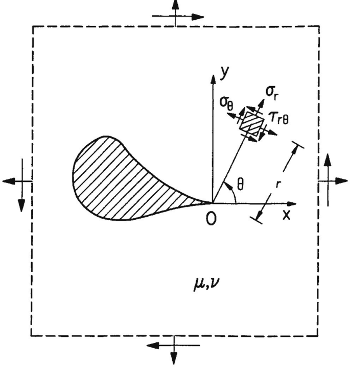
A rigid inclusion with a cuspidal point embedded in a matrix
$$ \begin{aligned} \sigma_{r} = & \frac{1}{{4\sqrt {2r} }}\left[ {k_{\text{I}} \left[ {5\cos \frac{\theta }{2} + (2\kappa + 1)\cos \frac{3\theta }{2}} \right] - k_{\text{II}} \left[ {5\sin \frac{\theta }{2} + (2\kappa - 1)\sin \frac{3\theta }{2}} \right]} \right] \\ \sigma_{\theta } = & \frac{1}{{4\sqrt {2r} }}\left[ {k_{\text{I}} \left[ {3\cos \frac{\theta }{2} - (2\kappa + 1)\cos \frac{3\theta }{2}} \right] - k_{\text{II}} \left[ {3\sin \frac{\theta }{2} - (2\kappa - 1)\sin \frac{3\theta }{2}} \right]} \right] \\ \tau_{r\theta } = & \frac{1}{{4\sqrt {2r} }}\left[ {k_{\text{I}} \left[ {\sin \frac{\theta }{2} - (2\kappa + 1)\sin \frac{3\theta }{2}} \right] + k_{\text{II}} \left[ {\cos \frac{\theta }{2} - (2\kappa - 1)\cos \frac{3\theta }{2}} \right]} \right] \\ \end{aligned} $$where the coefficients kI and kII are independent of the coordinates r, \( \theta \) and depend on loading conditions, the plate material and the geometrical shape of the inclusion at the cuspidal point.
Show that the strain energy density factor S is given by
$$ S = a_{11} k_{1}^{2} + 2a_{12} k_{1} k_{2} + a_{22} k_{2}^{2} $$where
$$ \begin{aligned} 16\mu a_{11} = & 2(\kappa - 1)\cos^{2} \frac{\theta }{2} + \kappa^{2} + (2\kappa + 1)\cos^{2} \theta \\ 16\mu a_{12} = & - [(\kappa - 1) + 2\kappa \;\cos \theta ]\sin \theta \\ 16\mu a_{22} = & 2(\kappa - 1)\sin^{2} \frac{\theta }{2} + \kappa^{2} - (2\kappa - 1)\cos^{2} \theta . \\ \end{aligned} $$ -
7.23.
Use Problem 7.22 to show that the angle formed by the fracture path with the tangent of the inclusion at the cuspidal point is given by
$$ \begin{aligned} & [(\kappa - 1) + 2(2\kappa + 1)\cos\,\theta ]\sin \theta \,k_{1}^{2} + 2[(\kappa - 1)\cos \theta + 2\kappa \;\cos 2\theta ]k_{1} k_{2} \\ & \quad + [ - (\kappa - 1) - 2(2\kappa - 1)\cos \theta ]\sin \theta \,k_{2}^{2} = 0 \\ \end{aligned} $$$$ \begin{aligned} & [ - (\kappa - 1)\cos \theta - 2(2\kappa + 1)\cos 2\theta ]\,k_{1}^{2} + 2[(\kappa - 1) + 8\kappa \;\cos \theta ]\sin \theta \,k_{1} k_{2} \\ & \quad + [[(\kappa - 1)\cos \theta + 2(2\kappa - 1)\cos 2\theta ]\,k_{2}^{2} > 0. \\ \end{aligned} $$ -
7.24.
Use Problem 7.23 to show that the angle formed by the fracture path with the tangent of the inclusion at the cuspidal point is calculated according to the maximum stress criterion by
$$ (1 + \kappa )k_{\text{I}} \tan^{3} \frac{\theta }{2} + (3\kappa - 1)k_{\text{II}} \tan^{2} \frac{\theta }{2} - (1 + 3\kappa )k_{\text{I}} \tan \frac{\theta }{2} - (\kappa - 1)k_{\text{II}} = 0 $$subject to the condition that \( \partial^{2} \sigma_{\theta } /\partial \theta^{2} < 0 \) and \( \sigma_{\theta } > 0 \).
-
7.25.
A rigid hypocycloidal inclusion is embedded in an infinite plate which is subjected to a uniaxial uniform stress \( \sigma \) at infinity (Fig. 7.25). The equation of the inclusion with respect to the frame Oxy is of the form
Fig. 7.25 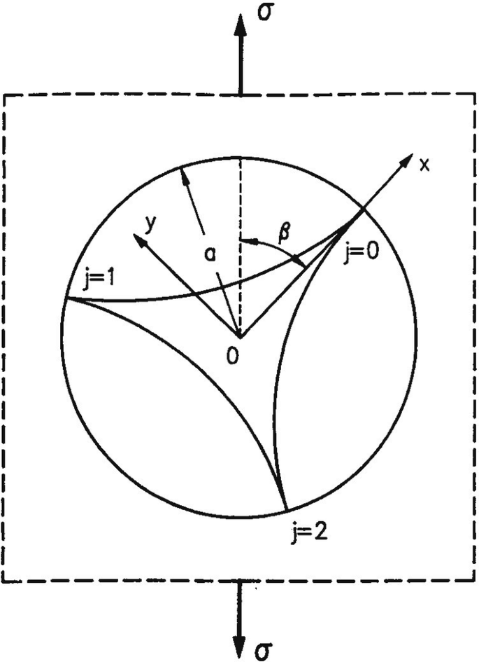
A rigid hypocycloidal inclusion embedded in an infinite plate
$$ z = \frac{2a}{3}\left( {\zeta + \frac{1}{2}\zeta^{ - 2} } \right) $$with
$$ z = re^{i\phi } ,\quad \zeta = e^{i\theta } $$and the stress \( \sigma \) subtends an angle \( \beta \) with the x-axis. For this problem the coefficients kI and kII of Problem 7.22 are given by
$$ k_{\text{I}}^{(j)} = \frac{{\sqrt {2a} }}{3\kappa }\sigma \left[ {\frac{\kappa - 1}{2} + \cos \left( {\frac{4\pi j}{3} - 2\beta } \right)} \right] $$$$ k_{\text{II}}^{(j)} = \frac{{\sqrt {2a} }}{3\kappa }\sigma \;\sin \left( {\frac{4\pi j}{3} - 2\beta } \right) $$with j = 0, 1, 2 for the three cuspidal points of the inclusion.
Plot the variation of the dimensionless quantities \( 12(r/a)^{1/2} \left( {\sigma_{\theta } /\sigma } \right) \) and \( \left( {72\mu S/\sigma^{2} a} \right) \) versus angle \( \theta \) for j = 0 and β = 25°, κ = 1.8. Find the angle \( \left( {\theta_{c} } \right)_{1} \) for which the former quantity becomes maximum, and the angle \( \left( {\theta_{c} } \right)_{2} \) for which the latter has a local minimum. These angles are the fracture angles according to the maximum stress and the SED criteria.
-
7.26.
For Problem 7.25, plot the variation of the critical stress and the fracture angle of the composite plate for a tensile applied stress \( \sigma \) according to the maximum stress criterion. Indicate the regions in which fracture starts from the more vulnerable corners of the inclusion.
-
7.27.
As in Problem 7.26 according to the SED criterion.
-
7.28.
The stress field at the end points of a rigid rectilinear inclusion embedded in an infinite plate is given by equations of Problem 7.22. For an inclusion of length 2l that subtends an angle β with the direction of applied uniaxial stress σ at infinity the coefficients kI and kII are given by
$$ k_{\text{I}} = \frac{\sigma \sqrt l }{2\kappa }\left( {\frac{\kappa - 1}{2} + \cos \;2\beta } \right) $$$$ k_{\text{II}} = - \frac{\sigma \sqrt l }{2\kappa }\sin \;2\beta . $$Plot the variation of fracture angle and critical stress for fracture of the composite plate versus angle β, for various values of \( \kappa \,\,(1 \le \kappa \le 3) \) when the applied stress σ is tensile.
-
7.29.
As in Problem 7.28 when the applied stress σ is compressive.
-
7.30.
For a mode-II crack, plot the variation of the circumferential stress \( \sigma_{\theta } \) and the strain energy density factor S versus polar angle \( \theta \) for \( \kappa = 2.0 \). Indicate the values of the angle \( \theta \) for which the former has a local maximum and the latter a local minimum. These values give the crack growth directions according to the maximum stress and the SED criteria.
-
7.31.
A large plate subjected to pure shear stress \( \tau \) contains a crack of length 2a (Fig. 7.26). Calculate the angle of crack extension \( \theta_{c} \) and the critical shear stress \( \tau_{c} \) for crack growth according to the maximum stress criterion for β = 45°, 60°, 75° and 90°.
Fig. 7.26 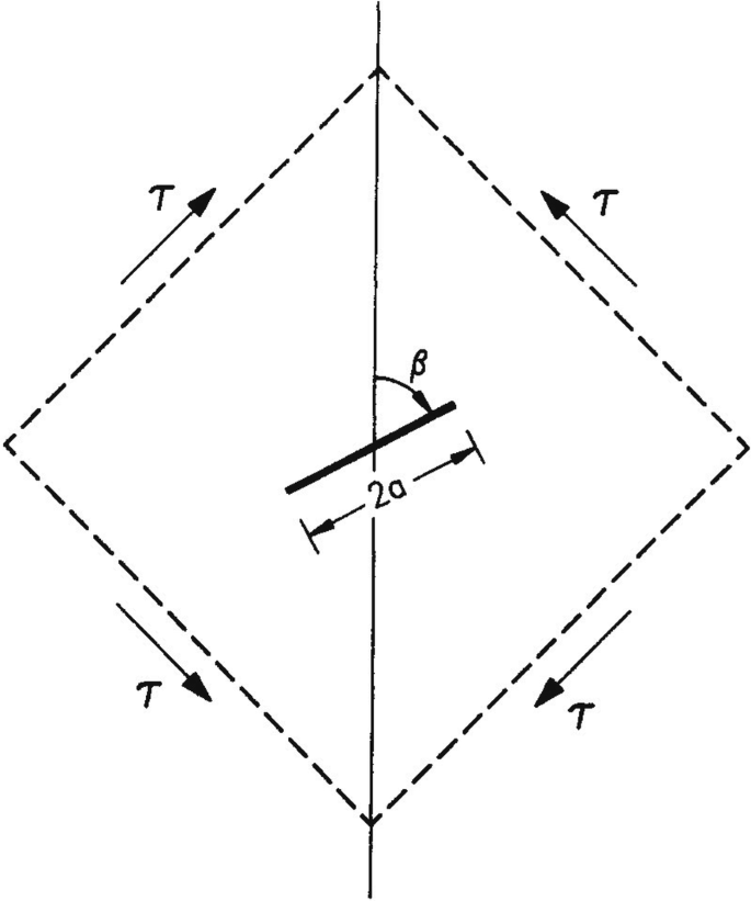
An inclined crack in a pure shear stress field


Rights and permissions
Copyright information
© 2020 Springer Nature Switzerland AG
About this chapter

Cite this chapter
Gdoutos, E.E. (2020). Strain Energy Density Failure Criterion: Mixed-Mode Crack Growth. In: Fracture Mechanics. Solid Mechanics and Its Applications, vol 263. Springer, Cham. https://doi.org/10.1007/978-3-030-35098-7_7
Download citation
DOI: https://doi.org/10.1007/978-3-030-35098-7_7
Published:
Publisher Name: Springer, Cham
Print ISBN: 978-3-030-35097-0
Online ISBN: 978-3-030-35098-7
eBook Packages: EngineeringEngineering (R0)