
Abstract
When a solid is fractured, work is performed to create new material surfaces in a thermodynamically irreversible manner. In Griffith’s theory of ideally brittle materials, the work of fracture is spent in the rupture of cohesive bonds. The fracture surface energy \( \gamma \), which represents the energy required to form a unit of new material surface, corresponds to a normal separation of atomic planes. For the fracture of polycrystals, however, the work required for the creation of new surfaces should also include: dissipation associated with nonhomogeneous slip within and between the grains; plastic and viscous deformation; and possible phase changes at the crack surfaces. The energy required for the rupture of atomic bonds is only a small portion of the dissipated energy in the fracture process. There are situations where the irreversible work associated with fracture is confined to a small process zone adjacent to the crack surfaces, while the remaining material is deformed elastically. In such a case the various work terms associated with fracture may be lumped together in a macroscopic term R (resistance to fracture) which represents the work required for the creation of a unit of new material surface. R may be considered as a material parameter. The plastic zone accompanying the crack tip is very small and the state of affairs around the crack tip can be described by the stress intensity factor .
Access this chapter
Tax calculation will be finalised at checkout
Purchases are for personal use only
References
Krafft JM, Sullivan AM, Boyle RW (1961) Effect of dimensions on fast fracture instability of notched sheets. In: Proceedings of crack propagation symposium, vol 1. College of Aeronautics, Cranfield (England), pp 8–28
Standard practice for R-Curve-Determination (1981). ASTM annual book of standards, Part I0, American society for testing and materials, E561–81, pp 680–699
Irwin GR (1948) Fracture dynamics. Fracture of metals. American Society for Metals, Cleveland, U.S.A., pp 147–166
Orowan E (1948) Fracture and strength of solids. In: Reports on progress in physics XII, pp 185–232
Author information
Authors and Affiliations
Corresponding author
Appendices
Examples
Example 5.1
A three-point bend specimen was tested according to the ASTM E399 procedure . The 0.2% offset yield stress of the material is \( \sigma_{Y} = 1200\,{\text{MPa}} \) and the modulus of elasticity is \( E = 210\,{\text{GPa}} \). The specimen was tested at a loading rate of \( 100\,{\text{kN}}/\hbox{min} \) and a type-I load-displacement record was obtained. A chevron starter notch was machined and the specimen was subjected to 30,000 cycles at Pmax = 45 kN and Pmin = 0. The final stage of fatigue crack growth was conducted for 50,000 cycles at Pmax = 30 kN and Pmin = 0. The specimen dimensions were measured as
The maximum load and the secant load of the test record were measured as Pmax = 86 kN and PQ = 80 kN.
Determine \( K_{\text{Ic}} \).
Solution
We first determine a conditional \( K_{\text{Ic}} (K_{Q} ) \). We have:
KQ is determined from Eq. (5.9). This equation can be put in the form
To facilitate calculation of KQ, values of f(a/W) are tabulated for specific values of a/W, according to ASTM
a/W | f (a/W) | a/W | f (a/W) |
|---|---|---|---|
0.450 | 2.29 | 0.500 | 2.66 |
0.455 | 2.32 | 0.505 | 2.70 |
0.460 | 2.35 | 0.510 | 2.75 |
0.465 | 2.39 | 0.515 | 2.79 |
0.470 | 2.43 | 0.520 | 2.84 |
0.475 | 2.46 | 0.525 | 2.89 |
0.480 | 2.50 | 0.530 | 2.94 |
0.485 | 2.54 | 0.535 | 2.99 |
0.490 | 2.58 | 0.540 | 3.04 |
0.495 | 2.62 | 0.545 | 3.09 |
– | – | 0.550 | 3.14 |
For our case (a/W) = 0.5. Thus, f(a/W) = 2.66. The specimen is loaded at a KI rate, \( \Delta K_{\text{I}} /\Delta t \), as
or
We have
KQ is determined as
We have
The maximum stress intensity factor during the first stage of fatigue growth of precrack is
so that
During the final stage of fatigue growth of precrack KI is
and
The above results indicate that all requirements of a valid \( K_{\text{Ic}} \) test according to ASTM E399 standard are satisfied and the conditional value KQ is equal to \( K_{\text{Ic}} \), that is
Example 5.2
Figure 5.15 shows the load-displacement record of a compact tension specimen tested according to ASTM E399 procedure to determine \( K_{\text{Ic}} \). The 0.2% offset yield stress of the material is 800 MPa. The specimen dimensions were measured as: W = 12 cm, B = 5 cm, a = 6 cm. Determine \( K_{\text{Ic}} \).

Determination of PQ on the load-displacement record of the compact tension specimen of Example 5.2
Solution
A conditional \( K_{\text{Ic}} (K_{Q} ) \) is first determined from Eq. (5.10). This equation can be put in the form
To facilitate calculation of KQ, values of f(a/W) are tabulated for specific values of a/W, according to ASTM
a/W | f (a/W) | a/W | f (a/W) |
|---|---|---|---|
0.450 | 8.34 | 0.500 | 9.66 |
0.455 | 8.46 | 0.505 | 9.81 |
0.460 | 8.58 | 0.510 | 9.96 |
0.465 | 8.70 | 0.515 | 10.12 |
0.470 | 8.83 | 0.520 | 10.29 |
0.475 | 8.96 | 0.525 | 10.45 |
0.480 | 9.09 | 0.530 | 10.63 |
0.485 | 9.23 | 0.535 | 10.80 |
0.490 | 9.37 | 0.540 | 10.98 |
0.495 | 9.51 | 0.545 | 11.17 |
– | – | 0.550 | 11.36 |
We have a/W = 0.5. Thus, f(a/W)= 9.66. To determine PQ in Eq. (1) we draw a secant line through the origin of the load-displacement record of Fig. 5.15 with slope equal to 0.95 of the initial slope of the record. We obtain
and
KQ is determined as
We have
and therefore
Example 5.3
The stress intensity factor of a crack of length 2a in a plate subjected to a tension field is given by
The crack growth resistance curve of the plate is expressed by
where a0 is the initial crack length and m is a constant.
Determine the critical stress \( \sigma_{c} \) and the critical length 2ac at the point of instability.
Solution
At the point of unstable crack growth we have from Eq. (5.11a) and the third Eq. (4.40)
Equation (4) renders
Equation (3) becomes
Equations (7) and (8) give the critical stress \( \sigma_{c} \) and the critical crack length 2ac at instability.
Example 5.4
Determine the stability condition for a double cantilever beam (DCB) (Fig. 4.14) subjected to an end load in a soft (load-controlled) or a hard (displacement-controlled) testing machine.
Solution
The compliance of the DCB is (Example 4.2)
From Eq. (1) we obtain
For stability in a soft (load-controlled) testing machine Eq. (5.18) becomes
From Eq. (1) we obtain
For stability in a hard (displacement-controlled) testing machine Eq. (5.19) becomes
Equations (3) and (5) express the stability conditions in a soft or a hard testing machine. Note that Eq. (5) is always satisfied for constant R. Equations (3) and (5) show that stability is achieved more easily with a hard than with a soft testing machine.
Example 5.5
A cylindrical pressure vessel with closed ends has a radius R = 1 m and thickness t = 40 mm and is subjected to internal pressure p. The vessel must be designed safely against failure by yielding (according to the von Mises yield criterion) and fracture. Three steels with the following values of yield stress \( \sigma_{Y} \) and fracture toughness \( K_{\text{Ic}} \) are available for constructing the vessel.
Steel | \( \sigma_{Y} ({\text{MPa}}) \) | \( K_{\text{Ic}} ({\text{MPa}}\,\sqrt {\text{m}} ) \) |
|---|---|---|
A: 4340 | 860 | 100 |
B: 4335 | 1300 | 70 |
C: 350 Maraging | 1550 | 55 |
Fracture of the vessel is caused by a long axial surface crack of depth a. The vessel should be designed with a factor of safety S = 2 against yielding and fracture.
For each steel:
-
(a)
Plot the maximum permissible pressure pc versus crack depth ac;
-
(b)
Calculate the maximum permissible crack depth ac for an operating pressure p = 12 MPa;
-
(c)
Calculate the failure pressure pc for a minimum detectable crack depth a = 1 mm.
Solution
Just as in Example 2.5, a material element of the vessel is subjected to a hoop \( \sigma_{\theta } \) and a longitudinal \( \sigma_{z} \) stress given by
The von Mises yield criterion expressed by Eq. (1.3) takes the form
From Eqs. (1) and (2) we obtain
or
Equation (3) gives the maximum pressure the vessel can withstand without failure by yielding. For the three steels available we obtain
pc (MPa) | ||
|---|---|---|
A | B | C |
19.9 | 30.0 | 35.8 |
For a long axial surface crack of depth a the stress intensity factor is (Fig. 5.16, Case 2 of Appendix 2.1).

A material element for the determination of stress intensity factor for a long axial surface crack of depth a
The fracture condition is expressed by
From Eqs. (1) to (3) we obtain
or
-
(a)
Based on the results of the previous table and Eq. (8) the maximum pressure versus crack depth curves for the three steels are shown in Fig. 5.17.
Fig. 5.17 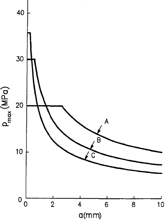
Maximum pressure pmax versus crack depth a for the three steels of Example 5.5
-
(b)
For p = 12 MPa the maximum permisible crack depths are calculated by Eq. (8) for the three steels as

ac(mm) | ||
|---|---|---|
A | B | C |
7.04 | 3.64 | 2.12 |
Note that at p = 12 MPa material A failed by yielding.
-
(c)
The failure pressure for a minimum detectable crack depth of a = 1 mm is calculated from Eq. (8) for the three steels as
pc (MPa) | ||
|---|---|---|
A | B | C |
19.90 (31.90) | 22.96 | 17.60 |
Note that material A although withstands a pressure Pcr = 31.90 MPa for a = 1 mm, it fails at pc = 19.90 MPa by yielding.
Example 5.6
A cylindrical pipe with inner radius b = 10 cm and outer radius c = 20 cm is thermally stressed due to a temperature difference \( \Delta T \) across the wall. Positive \( \Delta T \) indicates that the outside wall temperature is higher than the inside. The pipe contains an initial crack of length \( a = 1 \) mm emanating from its inner radius. The material of the pipe has yield stress \( \sigma_{Y} = 1000\,{\text{MPa}} \), Poisson’s ratio v = 0.3, modulus of elasticity \( E = 210\,{\text{GPa}} \), coefficient of thermal expansion \( \alpha = 6.6 \times 10^{ - 6} \,^\circ {\text{F}} \) and fracture toughness \( K_{\text{Ic}} = 100\,{\text{MPa}}\sqrt {\text{m}} \). Determine the maximum temperature difference \( (\Delta T)_{c} \) the pipe can withstand without failure, with a factor of safety S = 2 against yielding and S = 3 against fracture.
Solution
The maximum stress at the rim of the inner radius of the pipe is given by (Theory and Elasticity, by S.P. Timoshenko and J.N. Goodier, Third Edition, p. 449)
The condition of failure by yielding is expressed by
From Eqs. (1) and (2) we obtain
Thus,
Equation (4) gives the maximum temperature the pipe can withstand without failure by yielding.
The stress intensity factor \( K_{\text{I}} \) at the crack tip is (Case 2 of Appendix 2.1)
or
or
The condition of failure by fracture is expressed by
From Eqs. (6) and (7) we obtain
Equation (8) gives the maximum temperature the pipe can withstand without failure by fracture.
Comparing the values of \( (\Delta T)_{c} \) from Eqs. (4) and (8) we see that there is little difference between the prediction based on the maximum stress criterion and that obtained by fracture mechanics.
Example 5.7
A center cracked large plate of steel with thickness 10 mm is subjected to a uniform tension \( \sigma = 300\,{\text{MPa}} \) perpendicular to the crack plane. Calculate the maximum crack length the plate can withstand without failure. \( \sigma_{Y} = 860\,{\text{MPa}} \), \( K_{\text{Ic}} = 100\,{\text{MPa}}\sqrt {\text{m}} \).
Solution
The applied stress \( \sigma = 300\,{\text{MPa}} \) is smaller than the yield stress \( \sigma_{Y} = 860\,{\text{MPa}} \) of the material. Thus, the plate does not fail by yielding.
The plate thickness B = 10 mm is smaller than the minimum thickness required for plane strain \( B_{c} = 2.5\left( {K_{\text{Ic}} /\sigma_{Y} } \right)^{2} = 34\,{\text{mm}} \). Thus, the critical stress intensity factor Kc of the plate is not the plane strain stress intensity factor \( K_{\text{Ic}} \). It is calculated from Eq. (5.7) as
The stress intensity factor of a crack of length 2a in the plate is calculated as
The fracture condition is expressed by
Equations (1) to (3) show that the maximum crack length the plate can withstand is
Example 5.8
The critical strain energy release rate GR of the double cantilever beam of Fig. 4.14 subjected to opposite point loads P at its end is given by
where g0 and g1 are material constants and Δa = a – a0 is the crack growth increment with a the current and a0 the initial crack length.
The beam has a height of 2 h = 20 mm, unit thickness and initial crack length a0 = 100 mm. The material constants have the following values: E = 100 GPa, ν = 0.3 and plane stress condition prevail.
Determine the critical load Pc for unstable crack growth and the length Δa of stable crack growth for the following cases:
-
(a)
g0 = 0.002 and g1 = 0.05 MN/m
-
(b)
g0 = 0.001 and g1 = 0.015 MN/m
-
(c)
g0 = 0.0005 and g1 = 0.02 MN/m
Solution
The critical load Pc and length Δa of stable crack growth are determined from Eqs. (5.11a) and (4.40) as
For the double cantilever beam subjected to opposite concentrated loads P at its end for conditions of generalized plane stress we have (Example 4.2)
Equations (2) and (3) in conjunction with Eq. (1) take the form
By eliminating P in Eqs. (5) and (6), we obtain for the length Δa of stable crack growth
and for the critical load Pc for unstable crack growth
From Eqs. (7) and (8), we obtain following numerical results for the above three cases:
-
(a)
$$ \varDelta a = 20\,{\text mm},P_{c} = 43.7\,{\text kN} $$(9)
-
(b)
$$ \varDelta a = - 33\,{\text mm}, thus\,\varDelta a = 0,P_{c} = 30.3\,{\text kN} $$(10)
-
(c)
$$ \varDelta a = 50\,{\text mm},P_{c} = 24.7\,{\text kN} $$(11)
Problems
-
5.1.
A three-point bend specimen was tested according to the ASTM E399 procedure. The 0.2 percent offset yield stress of the material is \( \sigma_{Y} = 1\,{\text{GPa}} \) and the modulus of elasticity is \( E = 210\,{\text{GPa}} \). The specimen was tested at a loading rate of 60 kN/min. A chevron starter notch was machined and the specimen was subjected to 20,000 cycles at Pmax = 20 kN and Pmin = 0. The final stage of fatigue crack growth was conducted for 40,000 cycles at Pmax = 15 kN and Pmin = 0. The specimen dimensions were measured as
$$ \begin{aligned} & S = 40\,{\text{cm}},W = 10\,{\text{cm}},B = 5\,{\text{cm}} \\ & a_{1} = 4.993\,{\text{cm}} \\ & a_{2} = 5.008\,{\text{cm}} \\ & a_{3} = 5.999\,{\text{cm}} \\ & a({\text{surface}}) = 4.925\,{\text{cm}} \\ & a({\text{surface}}) = 4.916\,{\text{cm}}. \\ \end{aligned} $$The maximum load and the secant load of the test record were measured as Pmax = 108 kN, PQ = 100 kN. Calculate KQ and comment on the validity of the test.
-
5.2.
A compact tension specimen was tested according to the ASTM E399 procedure. The 0.2% offset yield stress of the material is \( \sigma_{Y} = 900\,{\text{MPa}} \) and the modulus of elasticity is \( E = 210\,{\text{GPa}} \). The specimen dimensions were measured as W = 10 cm, B = 5 cm, while the crack lengths at equal locations across the crack front were measured as 4.90, 4.93, 5.05, 4.95, 4.85 cm. The maximum load and the secant load of the test record were measured as Pmax = 70 kN and PQ= 65 kN. Calculate KQ and comment on the validity of the test.
-
5.3.
The load-displacement test record of the compact tension specimen of Problem 5.2 is shown in Fig. 5.18. Calculate KQ and comment on the validity of the test.
Fig. 5.18 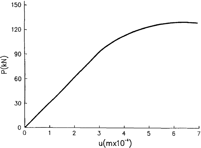
Load-displacement \( (P - u) \) record of the compact tension specimen of Problem 5.3
-
5.4.
A three-point bend specimen with S = 40 cm, W = 10 cm, a = 5 cm and B = 5 cm was tested according to the ASTM E399 procedure. The 0.2 offset yield stress of the material is 400 MPa. The secant load is PQ = 60 kN and the maximum load is Pmax = 65 kN. Calculate \( K_{\text{Ic}} \) and comment on its validity.
-
5.5.
A compact tension specimen of a steel with W = 20 cm, a = 9 cm and B = 8 cm was tested according to the ASTM E399 procedure. The 0.2 offset yield stress of the material is \( \sigma_{Y} = 900\,{\text{MPa}} \) and the secant load PQ was measured to be 300 kN. Calculate \( K_{\text{Ic}} \) and comment on its validity.
-
5.6.
Determine the maximum \( K_{\text{Ic}} \) value that may be determined according to ASTM standards on a 30 mm thick plate with 0.2 offset yield stress (a) 400 MPa, (b) 2000 MPa.
-
5.7.
Assume that the extension \( \Delta a \) of a crack of initial length ao is equal to the plane strain plastic zone radius calculated according to the Irwin model. For plane strain show that
$$ \frac{\Delta a}{{a_{0} }} \le 0.0212 \simeq 0.02. $$ -
5.8.
Use the result of the previous problem to justify the determination of PQ using a 5% secant offset line on the load-displacement record according to ASTM E399 procedure. For this reason use the result that when the load-displacement \( (P - u) \) record takes the form
$$ \frac{uEB}{P} = f(a/W) $$where B and W are the specimen thickness and width, and E the modulus of elasticity, the quantity
$$ H = \frac{{a_{0} }}{W}\frac{1}{f}\frac{{{\text{d}}f}}{{{\text{d}}\left( {a_{0} /W} \right)}},\quad f = f(a/W) $$takes an average value of 2.5 for the recommended range of values a0/W lying between 0.45 and 0.55.
-
5.9.
The crack growth resistance curve of a certain material at a thickness 2 mm is expressed by
$$ R = \frac{{K_{\text{lc}}^{2} }}{E} + \frac{1}{2}(\Delta a)^{0.5} \,{\text{MJ}}/{\text{m}}^{2} ,K_{\text{Ic}} = 95\,{\text{MPa}}\sqrt {\text{m}} ,E = 210 \times 10^{3} \,{\text{MPa}} . $$Consider a center cracked plate of width 10 cm and thickness 2 mm with a crack of length 1 cm. Calculate the length of stable crack growth, the critical crack length, and the critical stress at instability.
-
5.10.
As in Problem 5.9 for a center cracked plate of width 5 cm.
-
5.11.
Consider a double cantilever beam (DCB, Fig. 4.14) with dimensions: B = 2 cm, a = 50 mm, h = 10 mm. For the material of Problem 5.9 calculate the length of stable crack growth, the critical length, and the critical load at instability.
-
5.12.
Determine the stability condition for the double cantilever beam (DCB) of Problem 4.7 tested in a soft (load-controlled) or a hard (displacement-controlled) testing machine.
-
5.13.
As in Problem 5.12 for the strip of Problem 4.10.
-
5.14.
As in Problem 5.12 for the DCB of Problem 4.24.
-
5.15.
As in Problem 5.12 for a center cracked plate.
-
5.16.
Calculate the load required for crack growth of a double cantilever beam (Fig. 4.14) with a = 20 cm, h = 4 cm, B = 1 cm, E = 210 GPa and Gc= 200 kJ/m2.
-
5.17.
Calculate the critical stress for growth of a crack of length 2 mm in a large thin plate of steel, loaded by a uniform stress perpendicular to the crack plane. Take E = 210 GPa, γ = 2 Jm−2, γp= 2 × 10⁴ Jm−2.
-
5.18.
A sheet of glass with width 50 cm and thickness 1 mm is subjected to a tensile stress of 10 MPa. Determine the minimum crack length that would lead to fracture. Take the following properties of glass: E = 60 GPa, v = 0.25, γ = 0.5 J/m2, σf = 150 MPa.
-
5.19.
A center cracked plate of steel with width 10 cm is subjected to a uniform tension 200 MPa perpendicular to the crack plane. Calculate the maximum crack length the plate can withstand without failure. \( K_{\text{Ic}} = 55\,{\text{MPa}}\sqrt {\text{m}} \).
-
5.20.
Consider an edge cracked plate of steel with width 5 cm subjected to a uniform tension 200 MPa perpendicular to the crack plane. Calculate the maximum crack length the plate can withstand without failure. \( K_{\text{Ic}} = 55\,{\text{MPa}}\sqrt {\text{m}} \).
-
5.21.
A crack of length 2 mm emanates from a circular hole of radius 50 mm in a large plate of steel subjected to a uniform stress perpendicular to the crack plane. Calculate the maximum stress the plate can withstand without failure. \( \sigma_{Y} = 860\,{\text{MPa}} \), \( K_{\text{Ic}} = 100\,{\text{MPa}}\sqrt {\text{m}} \).
-
5.22.
A spherical vessel of steel with radius 1 m and thickness 40 mm contains a through crack of length 1 mm. Calculate the maximum internal pressure the vessel can withstand without failure. \( \sigma_{Y} = 860\,{\text{MPa}} \), \( K_{\text{Ic}} = 100\,{\text{MPa}}\sqrt {\text{m}} \).
-
5.23.
A crack of length 2 mm emanates from an elliptical hole with axes 100 and 50 mm in a large plate of steel subjected to a uniform stress perpendicular to the crack plane. Calculate the maximum stress the plate can withstand without failure. \( \sigma_{Y} = 860\,{\text{MPa}} \), \( K_{\text{Ic}} = 100\,{\text{MPa}}\sqrt {\text{m}} \).
-
5.24.
A center cracked plate of width 10 cm contains a crack of length 4 cm. The plate is subjected to a uniform stress perpendicular to the crack plane. Calculate the maximum stress the plate can withstand without failure. \( \sigma_{Y} = 450\,{\text{MPa}} \) and \( K_{\text{Ic}} = 25\,{\text{MPa}}\sqrt {\text{m}} \).
-
5.25.
Calculate the maximum load the three-point bend specimen of Problem 2.32 (Fig. 2.30) can withstand. \( \sigma_{Y} = 1500\,{\text{MPa}} \), \( K_{\text{Ic}} = 60\,{\text{MPa}}\sqrt {\text{m}} \). The factor of safety for failure by yielding is 3 and by fracture is 2.
-
5.26.
Calculate the maximum radial interference the shaft of Problem 2.36 (Fig. 2.33) can withstand. c = 5 cm, b = 2 cm, a =1 mm; E = 210 GPa, v = 0.3, \( \sigma_{Y} = 900\,{\text{MPa}} \), \( K_{\text{Ic}} = 100\,{\text{MPa}}\sqrt {\text{m}} \). The factor of safety for failure by yielding and fracture is 2.
-
5.27.
Calculate the maximum crack length the cylindrical pipe of Problem 2.37 can withstand when it is subjected to a temperature difference \( \Delta T = 200\,^\circ {\text{F}} \), across the wall. c = 15 cm, b = 10 cm; E = 210 GPa, v = 0.3, \( \alpha = 6.6 \times 10^{ - 6} \,^\circ {\text{F}} \), \( \sigma_{Y} = 900\,{\text{MPa}} \), \( K_{\text{Ic}} = 100\,{\text{MPa}}\sqrt {\text{m}} \). The factor of safety for failure by yielding and fracture is 2.
-
5.28.
Plot the allowable stress versus crack length curves for a large plate with a through crack subjected to a uniform stress perpendicular to the crack plane for the three steels of Example 5.5.
-
5.29.
Consider a circular disk of radius c = 20 cm with a hole of radius b = 10 cm rotating at an angular velocity \( \omega = 2\pi N/60 \), where N is the number of revolutions per minute. The disk contains an initial crack of length a = 1 cm emanating from its hole. The material of the disk has mass density \( \rho = 7800\,{\text{kg}}/{\text{m}}^{3} \), yield stress \( \sigma_{Y} = 1000\,{\text{MPa}} \), Poisson’s ratio v = 0.3, and fracture toughness \( K_{\text{Ic}} = 100\,{\text{MPa}}\sqrt {\text{m}} \). Determine the maximum number of revolutions per minute Nmax that the disk can rotate without failure, when the factor of safety is S = 2 and S = 3 against failure by yielding and fracture, respectively.
-
5.30.
The circular disk of Problem 5.29 may be constructed from the three steels of Example 5.5. For each steel:
-
(a)
Plot the maximum permissible number of revolutions per minute Nmax versus crack length;
-
(b)
Calculate the maximum permissible crack length for N = 5000 rpm;
-
(c)
Calculate Nmax for a minimum detectable crack a = 0.05 mm.
-
(a)
-
5.31.
The spherical vessel of Problem 5.22 may be constructed from the three steels of Example 5.5. The factor of safety against failure by yielding is 3 and by fracture is 2. For each steel:
-
(a)
Plot the maximum permissible pressure prnax versus crack length a;
-
(b)
Calculate the maximum permissible crack length acr for an operating pressure pc = 10 MPa;
-
(c)
Calculate pmax for a minimum detectable crack a = 0.05 mm.
-
(a)
-
5.32.
The cylindrical pipe of Example 5.6 may be constructed from the three steels of Example 5.5. For each steel:
-
(a)
Plot the maximum permissible temperature Tcr versus crack length;
-
(b)
Calculate the maximum permissible crack length acr for an operating temperature difference \( \Delta T = 200\,^\circ {\text{F}} \);
-
(c)
Calculate the critical temperature difference \( (\Delta T)_{cr} \) for a minimum detectable crack length a = 0.05 mm.
-
(a)
-
5.33.
A rectangular panel of width 1 m is subjected to a tensile load of 100 MN perpendicular to the width. The smallest crack size that can be detected is 1 mm. Two steels with the following values of yield stress and fracture toughness are available for constructing the panel: A. \( \sigma_{Y} = 860\,{\text{MPa}} \), \( K_{\text{Ic}} = 100\,{\text{MPa}}\sqrt {\text{m}} \) and B. \( \sigma_{Y} = 1550\,{\text{MPa}} \), \( K_{\text{Ic}} = 55\,{\text{MPa}}\sqrt {\text{m}} \). Find which material gives the smallest thickness of the panel.
-
5.34.
Calculate the maximum stress the plate of Problem 5.19 can withstand without failure when it has a thickness of 5 mm.
-
5.35.
Calculate the maximum stress the plate of Problem 5.24 can withstand without failure when it has a thickness of 20 mm.
-
5.36.
A long steel plate of width 20 cm and thickness 2 cm is subjected to a load 1.2 MN. Calculate the maximum crack length of a central or edge crack the plate can withstand without failure. \( \sigma_{Y} = 860\,{\text{MPa}},K_{\text{Ic}} = 100\,{\text{MPa}}\sqrt {\text{m}} \).

Appendix 5.1
Values of critical stress intensity factor KIc and 0.2% offset yield stress \( \sigma_{Y} \) at room temperature for various alloys.
Material | \( \sigma_{Y} \) | KIc | ||
|---|---|---|---|---|
MPa | ksi | MPa \( \sqrt {\text{m}} \) | ksi \( \sqrt {\text{m}} \) | |
300 Maraging Steel | 1669 | 242 | 93.4 | 85 |
350 Maraging Steel | 2241 | 325 | 38.5 | 35 |
D6AC Steel | 1496 | 217 | 66.0 | 60 |
AISI 4340 Steel | 1827 | 265 | 47.3 | 43 |
A533B Reactor Steel | 345 | 50 | 197.8 | 180 |
Carbon Steel | 241 | 35 | 219.8 | 200 |
Al 2014–T4 | 448 | 65 | 28.6 | 26 |
Al 2024–T3 | 393 | 57 | 34.1 | 31 |
Al 7075–T651 | 545 | 79 | 29.7 | 27 |
Al 7079–T651 | 469 | 68 | 33.0 | 30 |
Ti 6Al–4 V | 1103 | 160 | 38.5 | 35 |
Ti 6Al-6 V–2Sn | 1083 | 157 | 37.4 | 34 |
Ti 4Al-4Mo–2Sn–0.5Si | 945 | 137 | 70.3 | 64 |
Rights and permissions
Copyright information
© 2020 Springer Nature Switzerland AG
About this chapter

Cite this chapter
Gdoutos, E.E. (2020). Critical Stress Intensity Factor Fracture Criterion. In: Fracture Mechanics. Solid Mechanics and Its Applications, vol 263. Springer, Cham. https://doi.org/10.1007/978-3-030-35098-7_5
Download citation
DOI: https://doi.org/10.1007/978-3-030-35098-7_5
Published:
Publisher Name: Springer, Cham
Print ISBN: 978-3-030-35097-0
Online ISBN: 978-3-030-35098-7
eBook Packages: EngineeringEngineering (R0)