
Abstract
Mechanics of materials is one of the sciences underlying the design of any device that must support loads, from the simplest machines and tools to complex vehicles and structures. Three fundamental questions are examined. Will an object or structure support the loads acting on it? Answering this question requires introducing the state of stress, which describes the forces within a material. The state of stress must be determined at each point of a structure to ensure that it does not exceed the capacities of the materials used. What is the change in shape, or deformation, of an object subjected to loads? Design engineers must be concerned with how objects change shape due to the loads acting on them. What can be done if the external loads on an object cannot be determined by using the equilibrium equations? Supplementing the equilibrium equations with the relationships between the loads acting on an object and its deformation makes it possible to determine unknown reactions. The quantities used to analyze problems in mechanics of materials are expressed in terms of two types of units, the International System, or SI system of units, and the U.S. Customary system of units. The base units of the SI system are length in meters (abbreviated m), mass in kilograms (kg) and time in seconds (s). The base units of the U.S. Customary system are length in feet (ft), force in pounds (lb) and time in seconds. Studying mechanics of materials requires familiarity with the fundamentals of statics, including the concept of equilibrium, the equilibrium equations, methods for analyzing truss and frame structures, centroids of areas and distributed forces. Suppose that an object is subjected to two systems of forces and couples. If the sums of the forces in each system are equal and the sums of the moments about a point are equal, the systems are said to be equivalent.
Access this chapter
Tax calculation will be finalised at checkout
Purchases are for personal use only
Author information
Authors and Affiliations
Review Problems
Review Problems
Answers to even-numbered problems are given in Appendix G. Numbers in the answers, and in examples, are usually expressed to three significant digits. Problems that are more difficult and/or lengthy are marked with an asterisk.
-
1.1
The beam is subjected to a force and a couple. (a) Draw the free-body diagram of the beam. (b) Determine the reactions at A and B.
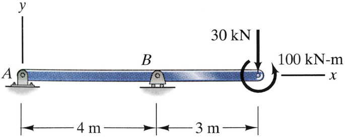
Problems 1.1–1.2
-
1.2
Determine the reactions at A and B if the 100-kN-m couple is moved to point A. Compare your answers to the answers to Problem 1.1.
-
1.3
(a) Draw the free-body diagram of the bar. (b) Determine the reactions at the fixed support A.
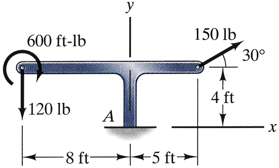
Problem 1.3
-
1.4
The floor exerts vertical forces on the drill press at A and B. What are they?
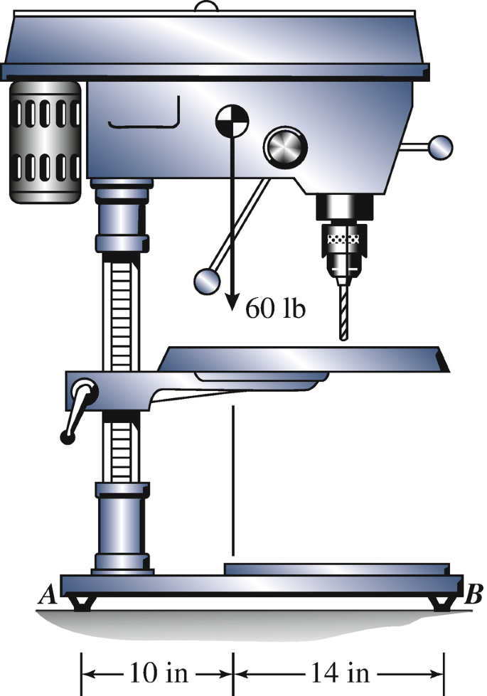
Problem 1.4
-
1.5
Determine the reactions exerted on the L-shaped bar by its supports at A and B.
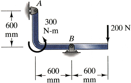
Problem 1.5
-
1.6
The free-body diagram of a portion of one of Fallingwater’s decks is shown. The mass of the isolated part is 14,700 kg. The free-body diagram is acted upon by its weight mg, forces P and V, and a couple M. Determine the values of P, V, and M.
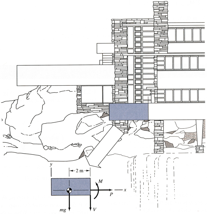
Problem 1.6
-
1.7
The two systems of forces and moments (a) and (b) are equivalent. Determine the magnitude of the force F, the angle α, and the magnitude of the clockwise couple C.
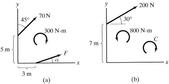
Problems 1.7–1.8
-
1.8
If you represent the equivalent systems of forces and moments (a) and (b) by a new equivalent system consisting of a single force R acting at the origin of the coordinate system and a couple M, what are the force R and the couple M?
-
1.9
The suspended mass m = 20 kg. Determine the axial force in the bar AB and indicate whether it is in tension or compression.
Strategy: The bar is a two-force member. Draw the free-body diagram of joint B.
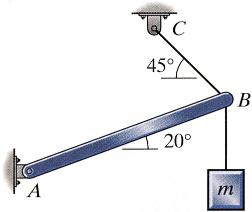
Problems 1.9–1.10
-
1.10
If the bar AB will safely support a compressive force no greater than 400 N, what is the largest mass m that can be suspended as shown?
-
1.11
Write the equilibrium equations for the entire truss and determine the reactions at the supports at A and D.
Problems 1.11–1.12
-
1.12
Determine the magnitude of the axial force in member BD of the truss and indicate whether it is in tension (T) or compression (C).
-
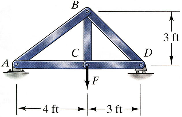
1.13
The force F = 3 kip. Determine the axial forces in members AC and CD of the truss and indicate whether they are in tension (T) or compression (C).
Problems 1.13–1.14
-
1.14
The members of the truss will safely support a tensile axial force of 4 kip and a compressive axial force of 2 kip. Based on these criteria, what is the largest safe value of F?
-
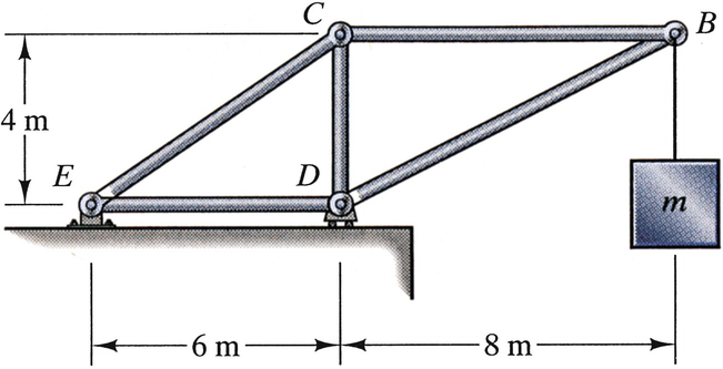
1.15
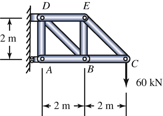
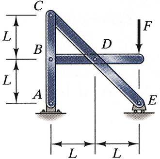
The compressive axial force in member CD due to the suspended mass m is 4 kN. Determine the axial forces in members BC and BD, and indicate whether they are in tension (T) or compression (C).
Problems 1.15–16
-
1.16
The suspended mass m = 200 kg. Determine the magnitudes of the axial forces in members CE and DE, and indicate whether they are in tension (T) or compression (C).
-
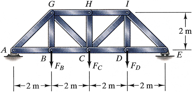
1.17
The loads FB = 40 kN, FC = 60 kN and FD = 20 kN. Determine the magnitudes of the axial forces in members BC, CG, and GH, and indicate whether they are in tension (T) or compression (C).
Problem 1.17
-
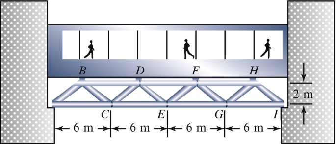
1.18
The Warren truss supporting the walkway is designed to support 50-kN vertical loads at B, D, F, and H. If the truss is subjected to these loads, what are the resulting axial forces in members AC, BC, and BD? Indicate whether the axial forces are tensile (T) or compressive (C).
Problems 1.18–1.19
-
1.19
The Warren truss supporting the walkway is designed to support 50-kN vertical loads at B, D, F, and H. If the truss is subjected to these loads, what are the resulting axial forces in members CE, DE, and DF? Indicate whether the axial forces are tensile (T) or compressive (C).
-
1.20
Determine the reactions on member CDE of the frame.
Problem 1.20
-
1.21
The bucket of the front-end loader is supported by a pin support at C and the hydraulic actuator AB. If the mass of the bucket is 180 kg and the system is stationary, what is the axial load in the hydraulic actuator?
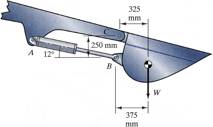
Problem 1.21
-
1.22
The suspended crate weighs 2000 lb and the angle α = 40°. If you neglect the weight of the crane’s boom ACD, what is the axial force in the hydraulic cylinder BC?
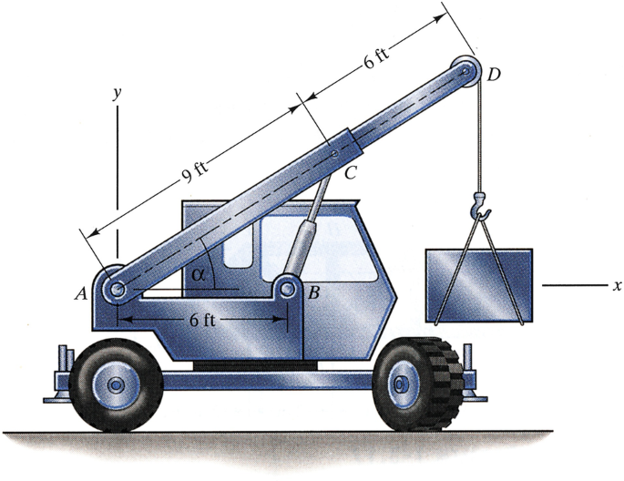
Problems 1.22–1.23
-
1.23
The suspended crate weighs 2000 lb and the angle α = 40o. If you neglect the weight of the crane’s boom ACD, what are the x and y components of the reaction exerted on the crane’s boom by the pin support A?
-
1.24
Determine the axial force in member BE of the frame.
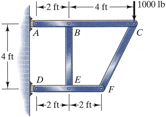
Problems 1.24–1.25
-
1.25
Determine the reactions at the frame’s supports A and D.
-
1.26
The system shown supports half of the weight of the 680-kg excavator. If the system is stationary, what is the axial load in member AB?
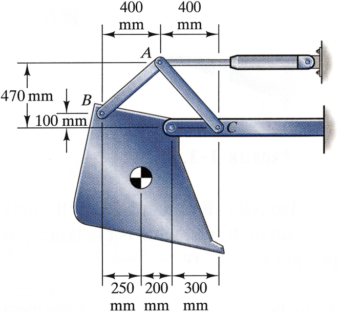
Problems 1.26–1.27
-
1.27
The system shown supports half of the weight of the 680-kg excavator. If the system is stationary, what is the axial load in member AC?
-
1.28
A person applies the 150-N forces shown to the handles of the pliers. Determine the axial force in the link AB.
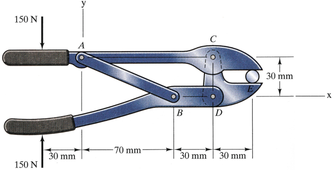
Problems 1.28–1.29
-
1.29
A person applies the 150-N forces shown to the handles of the pliers. Determine the x and y components of the reaction exerted on the upper handle AC of the pliers at C.
-
1.30
Member ABC of the frame has a pin at C that is supported by a smooth horizontal slot in member DC. Determine the reactions at the pin supports at A and E.
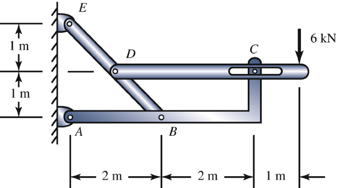
Problems 1.30–1.31
-
1.31
Member ABC of the frame has a pin at C that is supported by a smooth horizontal slot in member DC. Determine the magnitude of the force exerted on member BDE by the pin at B.
-
1.32
Determine the coordinates of the centroid of the area.
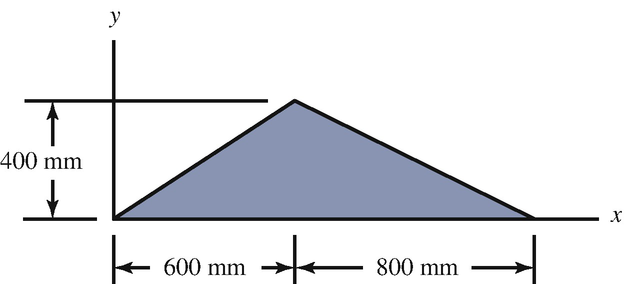
Problem 1.32
-
1.33
The area in Fig. (a) is the cross section of an L203 × 152 × 25.4 rolled steel shape (see Appendix E). Approximate the area of the cross section by ignoring the curved corners as shown in Fig. (b) and determine the coordinates of the centroid of the cross section. Compare your results with those given in Appendix E.
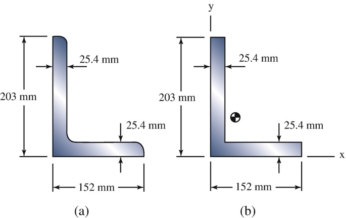
Problem 1.33
-
1.34
Determine the x and ycoordinates of the centroid of the area.
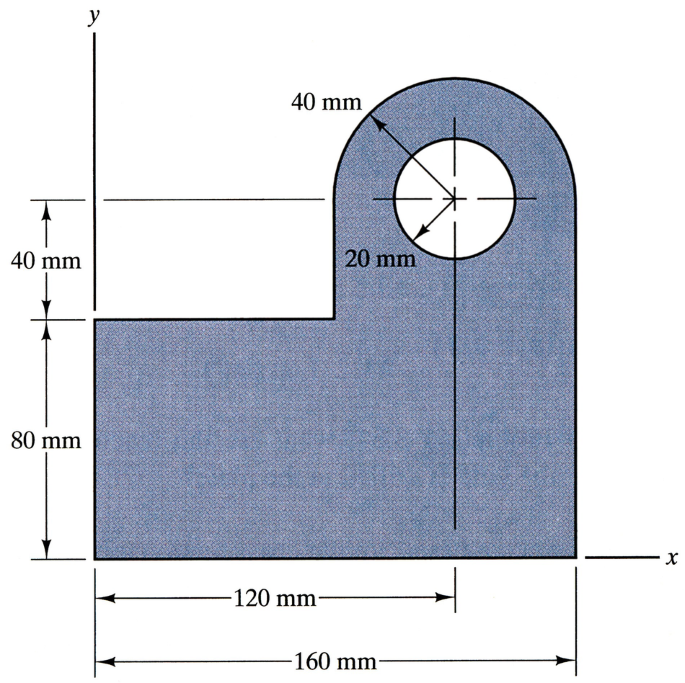
Problem 1.34
-
1.35
The steel plate is homogeneous, of uniform thickness, and weighs 10 lb. (a) Determine the x coordinate of the plate’s center of mass. (b) What are the reactions at A and B?
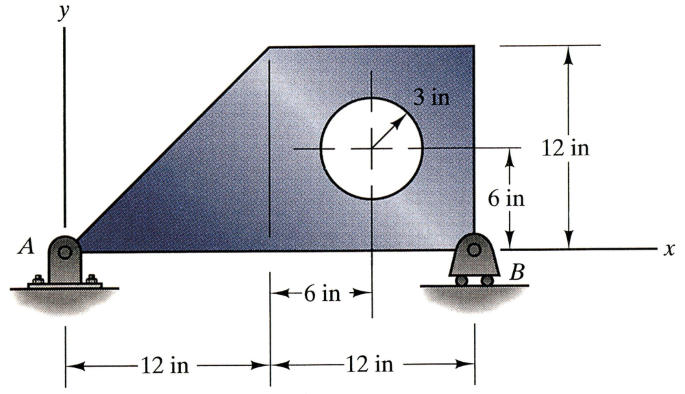
Problem 1.35
-
1.36
The area of the homogeneous plate is 10 ft2. The vertical reactions on the plate at A and B are 80 lb and 86 lb, respectively. Suppose that you want to equalize the reactions at A and B by drilling a 1-ft diameter hole in the plate. At what horizontal distance from A should the center of the hole be placed?
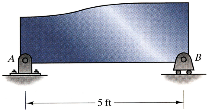
Problems 1.36–1.37
-
1.37∗
In Problem 1.36, what are the reactions at A and B after the hole is drilled in the plate?
-
1.38
The beam has a circular cross section with a diameter of 100 mm and consists of aluminum alloy with mass density ρ = 2900 kg/m3. (a) Determine the reactions at A and B. (b) If you represent the bar’s weight by a uniformly distributed load w, what is the value of w?
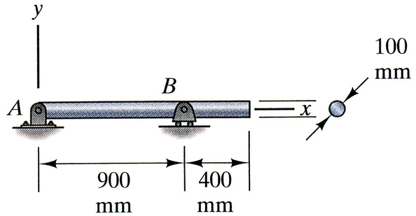
Problem 1.38
-
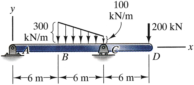
1.39
Determine the reactions at A and B.
Strategy: Treat the distributed load as two triangular distributed loads, and represent each distributed load by an equivalent force.
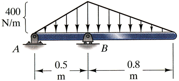
Problem 1.39
-
1.40
The beam is subjected to a distributed load given by the equation shown. Determine the reactions at A and B.
Strategy: Integrate to determine the total force and moment exerted by the distributed load.
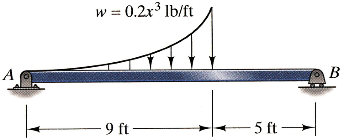
Problem 1.40
-
1.41
The aerodynamic lift of the wing is described by the distributed load w = − 300(1 − 0.04x2)1/2 N/m. Determine the magnitudes of the force and the moment about R exerted by the wing’s lift.
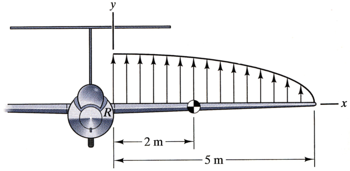
Problems 1.41–1.42
-
1.42
The mass of the wing in Problem 1.41 is 27 kg, and its center of mass is located 2 m to the right of the wing root R. Including the effects of the wing’s lift, determine the reactions exerted on the wing at R where it is attached to the fuselage.
-
1.43
Determine the reactions at A and C.
Problem 1.43
-
1.44∗
A plane surface of area A in the x-y plane is subjected to a uniform pressure p0. Show that this distributed load can be represented by an equivalent force of magnitude p0A whose line of action passes through the centroid of A.
Strategy: Write integral expressions for the total force and the total moment about the origin due to the uniform pressure, and use the definitions of the centroid of an area.
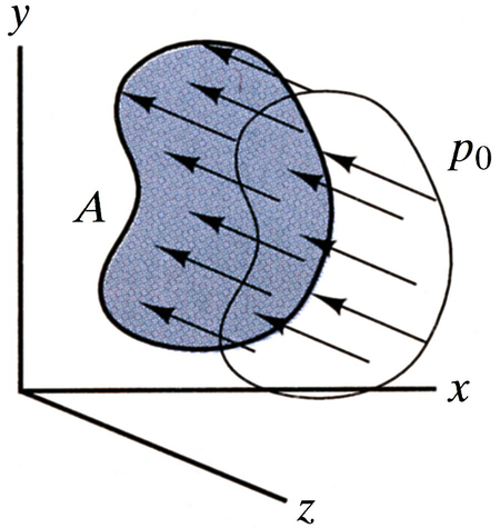
Problem 1.44
-
1.45
The beam is subjected to a distributed couple c, defined such that each infinitesimal element dx of the beam is acted upon by a counterclockwise couple c dx. If c = c0 = constant from x = 0 to x = L, determine the reactions at A and B.
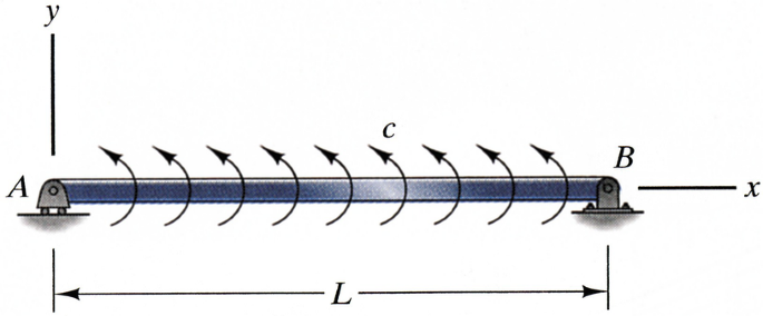
Problems 1.45–1.46
-
1.46
The distributed couple acting on the beam is given by the equation c = (x/L)c0, where c0 is a constant. Determine the reactions at A and B.
-
1.47
A pile is being slowly pushed into the ground by a vertical force F. The friction of the ground exerts a distributed axial force q, defined such that each infinitesimal element dx of the pile is acted upon by an axial force q dx. If q = 400(1 − 0.4x2/L2) lb/ft and L = 30 ft, determine the force F at the instant shown. (The pile’s weight and the force exerted by the ground at the bottom of the pile are negligible in comparison to the frictional force exerted along the pile’s length.)
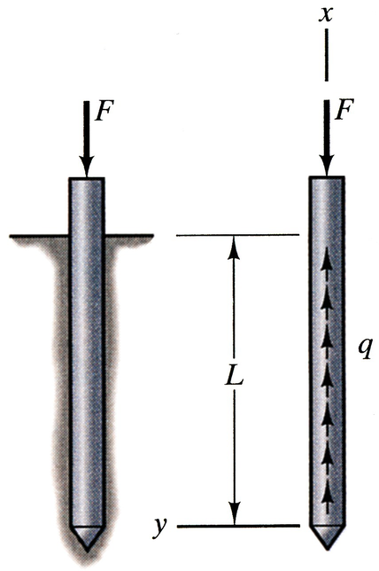
Problem 1.47


Rights and permissions
Copyright information
© 2020 Springer Nature Switzerland AG
About this chapter
Cite this chapter
Bedford, A., Liechti, K.M. (2020). Introduction. In: Mechanics of Materials. Springer, Cham. https://doi.org/10.1007/978-3-030-22082-2_1
Download citation
DOI: https://doi.org/10.1007/978-3-030-22082-2_1
Publisher Name: Springer, Cham
Print ISBN: 978-3-030-22081-5
Online ISBN: 978-3-030-22082-2
eBook Packages: EngineeringEngineering (R0)