
Abstract
Digitalization in manufacturing, also known as Industry 4.0, and Cyber Physical Systems (CPS) may turn ordinary manufacturing systems, usually designed for mass-production, into highly flexible and reconfigurable manufacturing system for mass customization purposes. The huge potential of the digital information management and real-time data management introduced by Industry 4.0 will be a key enabler for further developments in mass customization manufacturing. Increasing customization capabilities means increasing product variability and producing small quantities in a highly flexible way; this impacts the production process and the business process as well. Such reconfigurable CPS promise improvements of the production processes efficiency. In order to disseminate this production strategy to students and industry, the authors created a simple case study in order to introduce these aspects in a learning factory environment. This paper presents a pilot case study implemented in the Smart-Mini Factory laboratory at the Free University of Bolzano for educational and research purposes. The pilot case study aims at introducing a digital information management since the early first steps of the business process, combining Computational Design techniques and CPS. The authors discuss a simple pilot case that will be used mainly for dissemination purposes towards people not addicted to CPS and digital environments such as students and SME’s entrepreneurs. In the upcoming academic year, the demonstrator will be tested for the first time in the course Production Systems and Industrial Logistics with engineering students. In addition, the use of the demonstrator in industry seminars on mass customization and computational design is planned.
You have full access to this open access chapter, Download conference paper PDF
Keywords
1 Introduction
The increasing request for individuality of customers intensifies the trend towards mass customization. The producer, which is able to produce a product to low prices and with customer specific characteristics as quickly as possible, has the highest competitive advantage on the market. Therefore, mass customization is also an issue in engineering education and consequently also in the context of education in learning factories. In the sense of Industry 4.0, it would be an extensive goal if the production system could adapt to the requirements of the individual product in real time and therefore automatically adjust its production and assembly processes. Learning Factories should try to communicate these ambitious goals to students or seminar participants from industry by means of practical demonstrators.
This paper describes a case study at the Smart-Mini Factory (a learning factory lab) of the Free University of Bozen-Bolzano, which implemented such a demonstrator. In the case study, the assembly system is adapted to an individual product in real time by using Computational Design and CPS. The paper is structured as follows: after a short introduction, the state of the art in mass customization, reconfigurable production systems, Computational Design and the integration of CPS is shown. Subsequently, the concept of the case study or the demonstrator is explained and its implementation is described.
2 State of the Art
2.1 State of the Art in Reconfigurable Production Systems and Mass Customization
The concept of mass customization was first expounded formally in the book “Future Perfect” by Davis in 1989 [1]. It means the production of products, which have been customized for the customer, at production costs similar to those of mass-produced products [2]. Mass customization allows customers to select attributes from a set of pre-defined features in order to design their individualized product, by which they can fulfil their specific needs and take pride in having created a unique result [3, 4]. Mass customization brings radical changes to methods used to operate traditional manufacturing enterprises [5,6,7,8,9,10]. Manufacturing systems in a mass customization environment should be able to produce small quantities in a highly flexible way and to be rapidly reconfigurable [4, 11].
In the past, several concepts for manufacturing system design have been discussed in scientific literature: from flexible manufacturing systems (FMS) [12] to reconfigurable manufacturing systems (RMS) [5] as well as the concept of changeable and agile manufacturing systems [13]. Such manufacturing systems fit the needed requirements for mass customization manufacturing better than a traditional one.
The latest trend in mass customization is digitalization in manufacturing, also known under the term Industry 4.0 or CPS. The large potential of Industry 4.0 will be a key enabler for further developments in mass customization manufacturing [14]. Intelligent, cognitive and self-optimizing manufacturing systems can learn and there-by perform self-determined changes in production systems [15]. To reach such a next level of changeability it is necessary to equip manufacturing systems with cognitive capabilities in order to take autonomous decisions in even more complex production processes with a high product variety [16].
2.2 State of the Art in Computational Design
Computational Design is a term widely adopted to describe all the disciplines and the approaches that lead the design and the engineering processes applying computer aided methods and tools, such as: Parametric Design, Algorithmic Design, Generative Design, etc. Nowadays is mostly applied in constructions and building industry, but may be effectively applied to all Engineer-to-Order (EtO) industries, according to Wortmann classification [17].
The definition provided by Jabi in 2013 [18] summarizes a complex debate in the scientific community since the 1940s’ writings of architect Luigi Moretti [19] and the mathematical origins of parametric modelling. Lots of authors argue that everyone from Architecture, Design and Art disciplines always adopted parametric models to generate their ideas, such as Burry [20]. This complex framework generates difficulties in providing a clear definition about Parametric Design technique. After 70 years, the debate still goes on.
According to Woodbury [21], Parametric Design may be considered a huge family that includes all techniques leading geometry changes through parameters changes. Generative Design is based on algorithmic and parametric modelling and is a fast technique to explore design possibilities or design optimizations. Mostly, it applies nature’s evolutionary approach to design [22, 23].
Schumacher in his Parametricist Manifesto [24] points out stylistic application of Parametric and Generative Design techniques. Unfortunately, Schumacher neglects the difference between tool use and tool making as defined by Aranda and Lasch et al. [25, 26]. Beyond stylistic application, Scheurer [27] and Arnold Walz (designtoproduction) are supporting architects, planning experts and manufacturers in order to reach new standards of efficiency, safety and quality in complex and highly customized projects. They handle geometry optimization, computation of quantities, production planning and machine data to facilitate the installation process on construction sites. The authors successfully tested the application of Computational Design techniques in EtO environment pushing mass customization capabilities, for further details, they kindly invite readers to refer to previous publications [28].
2.3 State of the Art in Integration of CPS
Contrary to what common sense could say, heterogeneity of components in modern industrial systems may be a favourable condition due to several facts [29], as spanning industrial activities through different norms or application-specific requirements. Moreover, CPS are intrinsically heterogeneous systems due to the natural difference between its constitutive layers, i.e., physical, platform and software [30]. In this con-text, integration may be understood as the necessary steps that permits a body of disparate systems to be treated as a whole [31]. Because the authors are only interested in integration of software layers, their specific concern is that of interoperability, i.e. the ability of a software layer to use and share information and/or functionalities of another software layer by adhering to common standards [32]. Interoperability may be technical, syntactic and sematic [33].
At this point, integration of Cyber-Physical Production System (CPPS) becomes familiar with a long history of effort to integrate disparate digital platforms that begins in office environments and the term Enterprise Service Bus (ESB) appears to describe the software and hardware infra-structure capable of enabling seamless interoperability between systems [34]. In industrial environments, term Manufacturing Service Bus (MSB) was coined as an equivalent to ESB [35].
The integration of the IT landscape of the factory floor with enterprise level IT systems have been approached by several authors and technical reports. In [36] the concept of Service Oriented Architecture (SOA) is widely explained from the perspective of manufacturing systems and an architecture for MSB is presented. The European Innovation Project SOCRADES [37] presents a MSB system based on web services. The European In-novation project IMC-AESOP [38] (Architecture for Service-oriented Process, Monitoring and Control) proposes an integration approach for CPPS based on cloud technologies. Authors in [39] describe the integration of the shop floor with the ESB and other business activities of the Business Domain.
Those approaches rely heavily on web-services and XML-based technologies, which are dominant in office/enterprise systems and ISA-95 standard [40]. Unlike the precedent works, in this paper the authors prefer to focus in communication technologies that are more suitable for CPS, focusing in efficiency and speed of the data transfer. For this reason, they decided to rely in the communication system available in ROS (Robot Operative System) [41] to assure the integration of the nodes per-forming the assembly process. This approach behaves the challenge of adapting the software layer of every CPS to be compatible with ROS, that was primarily developed for Linux platforms. In fact, address the challenge of developing the necessary software tools to integrate the required systems via network with ROS. Further, the authors still rely in XML-based technologies to integrate the assembly system with the frontend dedicated to the customer.
3 Concept of the Case Study
3.1 Computational Design for Reconfigurable Product Engineering
During their previous research activities [28], the authors analyzed a relationship between the adoption of CPS and the digitalization of design and engineering processes though a pilot case study. This research activities tested the efficiency and the effectiveness of Parametric and Generative Design techniques within a real production system, highlighting huge benefits which can be achieved without huge investments on the production system itself. The lack of controlling strategies and information management based on CPS has been identified as the main limit.
Following these promising results and according to the planned activities within the Smart-Mini-Factory laboratory, the authors developed a specific algorithm that aims at simulating a high reconfigurable product within different x-to-order environments. The algorithm should offer a prototype mock-up of an information management platform based on Parametric and Generative design techniques.
In order to fulfil the objectives previously identified, the algorithm has been developed according to a free customization, defining these specific design intents:
-
the reconfiguration of the product must be performed both at features level and at geometrical level in an assembly space that could change time-by-time;
-
the reconfiguration of the product must be performed real-time and the algorithm should transmit assembly information and trigger the production process any time by a real-time connection within the intelligent and hybrid assembly system of the Smart-Mini-Factory Laboratory;
-
any scripting skill should not be required during the reconfiguration of the product, in order to make the algorithm accessible to any figure who could lead the process (e.g. final customer, selling agent, product developer, etc.).
According to the first design intent, the authors identified the TETRIS© game as the best example of performing a high-reconfigurable product design task. Number of pieces are limited to four, but, differently to the game, the user can select which piece he would use and freely change the order during the design task. Furthermore, the algorithm does not limit the alignment of the pieces (in the game limited to the bottom line) but let the user free of placing the pieces within the assembly space.
The reconfiguration of the product can be performed real-time thanks to the capability by the user of controlling all the parameters that lead the assembly. User can transmit assembly information and trigger the production process anytime, though a XML-RPC communication protocol.
The algorithm is structured though four main steps:
-
assembly space (domain), pieces and geometric transformation definitions (see Fig. 1);
Fig. 1. 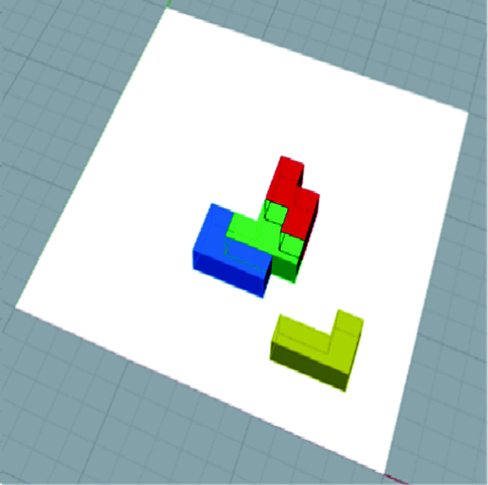
Assembly space (domain)
-
geometry analysis;
-
assembly information and communication protocol definitions;
-
GUI definition.

In a first step the algorithm defines the assembly domain, which has been defined as a 2D plane for convenience. The algorithm can apply parametric transformations on the main definition of the pieces: rotations of 90 degrees steps and translations according to the grid definition.
During a second step, the algorithm performs a geometry analysis in order to detect the following issues that may compromise a correct assembly:
-
collision detection;
-
assembly order (or priority).
The assembly order (or priority) has to be defined depending on the assembly process that has to be leaded. Whether the assembly is performed in a horizontal plane, any priority definition should not be performed. Whether the assembly is performed in a vertical plane, the algorithm must define the correct assembly order, identifying priorities of the pieces that have to be placed on bottom, under the condition that the assembly robot usually operates from the top according to a convexity analysis (see Fig. 2).

Convexity analysis
During a third step, the algorithm collects the assembly information that has to be transmitted to the assembly robot. The assembly information has been identified as follow:
-
piece ID;
-
assembly position (though coordinates) within the assembly domain;
-
rotation on the main definition of the piece (in degrees or rad).
This information is transmitted to the assembly robot though a XML-RPC call.
In the last step the algorithm defines a GUI for controlling the algorithm and all the parameters leading pieces and geometric transformation definitions. The interface is shortly described in the description the next section.
3.2 Components of the Assembly System
Following the agent paradigm, the assembly system’s design addresses each component of the manufacturing station as an autonomous entity capable of making its own decisions and autonomously retrieve any necessary resource of the network. The components are:
-
An adept Cobra i400 robots, a four-axis manipulator with a SCARA base and one additional wrist joint. Its controller is a SmartController CX with Ethernet capability. It runs the V+real-time operating systems is capable of execute concurrently up to 24 processes.
-
The Adept FlexiBowl is a rotary feeder for loose parts with less than 80 g. It can be actuated using a specific protocol based on UDP/IP over Ethernet.
-
A Basler scout Giga-Ethernet camera. It handles the image acquisition and automatically sends it using the GiGe protocols, which is based over UDP/IP.
-
A gateway server.
By then self, the FlexiBowl system and the Basler camera do not cope with the requirements of a CPS, so they cannot be integrated into the CPPS. This problem is overridden using the concepts of administration shield [42]. In practice, the FlexiBowl is connected to an Arduino YUN to its Ethernet port and the Balser camera is connected to a desktop computer running Linux with 3 Gb or RAM and an Intel i7 processor to reach the requirements of processing characteristics of computer vision system. Both systems as CPS will be called Smart Feeder and Smart Vision System respectively. Finally, the authors underline that the Adept Cobra i400 robot is already a CPS thanks to its Adept V+multitasking real-time operating systems and its hardware. Moreover, this robot will be the central entity of the CPPS that will receive the product assembly order and retrieve the required resource of the system to autonomously complete the order.
4 Implementation in the Smart-Mini Factory
4.1 User Interface Applied for Reconfigurable Product Engineering
The GUI is structured in two main sections (see Fig. 3):

The programmed GUI
-
control windows;
-
preview window.
The control windows are located at the side of the screen and they are the main interface for the user. The user can check parameters and assembly results though the preview window that is located in the middle of the screen. Changing parameters in control windows, starts algorithm’s geometry analysis step that is performed in the background and controls the activation of the “Ready to assembly” button. This button communicates to the user whether collision occurs and invites him to check the geometry. As soon as any issue is not detected, the user can transmit assembly information through the “Ready to assembly” button that let the algorithm open the communication channel with the listeners terminal and transmit the information to the assembly robot.
The algorithm and the GUI have been installed and adapted for a Touch Table available in the laboratory (Fig. 5). This system provides a simple and attractive interaction with the GUI thanks to its multi-touch feature, highlighting algorithm capabilities to be used in different scenarios according to the second and the third design intents. Though the Touch Table, students, visitors, professionals and researchers as well, could appreciate the capabilities of an information management platform based on Parametric and Generative design techniques and having a better understanding of benefits provided by CPS aiming at enhancing mass customization capabilities of production system within the “Industry 4.0” vision.
4.2 Network Specifications, CPS Coordination and Orchestration
There are mainly two different kind of data exchanged in industrial systems: (i) configuration data, that is related to remote management of systems and operation support and (ii) process data that is related to the state of process. Each category of data as its own requirements regarding network latency, jitter and reliability. To cope those requirement, the authors selected Publish and Subscribe for process data and Services for configuration data. Due to the pervasiveness of Ethernet compatibility in the available devices the authors chosen as the back-bone of the network of the CPPS a VLAN on switched Ethernet inside the Campus Area Network (CAN) of the Free University of Bolzano. The ROS-compatible Publish and Subscribe and services system and the XML-RPC messaging define two separate networks as in Fig. 4.

Subdivision of the system network
At a high level the authors differentiate their systems in 4 states as represented in Fig. 5, namely AS assembling, DE disassembling, SE searching and SB stand-by. The pro-cess begins in the SB state, where the robot is waiting for the external call from the Customer Relationship Management (CRM) product customization web-based front-end. Once the order is sent to the robot the system pass to the AS state, where the algorithm runs the pick and place operation for the assembly of the product. When a piece is required the system pass to the state SE, where the camera and the feeder will be used to search the required piece. Once the required piece is found, the system pass to the AS state. If the reconfiguration order is received the system pass, only if necessary to the state DE, where the necessary pieces are dissembled in order to reconfigure the product.

States of the assembly process
As stated before, all the assembly algorithm is placed inside the SCARA robot which is able to retrieve the state of the other CPS through Publish and Subscribe mechanism and to command them using services.
The image processing technique was based in the optimized Canny Algorithm presented in [43]. After a noise removal and contour detection, lines where extracted using the Hough transform [44]. Once the proper lines are filtered, the shapes were classified by noting that edges of the shapes under study are proportional to either one, two or three times the length of the underlying square. Such property allows us to verify the geometry of all shapes and also to discriminate between T and S shapes. The easiest approach to discriminate between Right-L and Left-L shapes, consist in the computation of the (signed) angle between the longest orthogonal segments of the L.
5 Conclusions
This paper discusses a case study for a simple reconfigurable CPPS used as a show-case and a demonstrator at the Smart-Mini Factory (a learning factory lab) of the Free University of Bozen-Bolzano. The case study has been completed applying both Computational Design techniques and connectivity of CPS. The connectivity layer has been developed over an Ethernet hardware assuring seamless integration of the Touch Table and the assembly system as well all its components. The authors would like to encourage other initiatives in order to explore capabilities of a wider digitalization along the whole value-chain system towards real-time reconfigurable CPPS.
Since the laboratory has been newly founded, the presented case study and the demonstrator have not yet been tested in teaching. In the upcoming academic year, the demonstrator will be tested for the first time in the course Production Systems and Industrial Logistics with engineering students. In addition, the use of the demonstrator in industry seminars on mass customization and computational design is planned.
References
Davis, S.M.: From “future perfect”: mass customizing. Plan. Rev. 17(2), 16–21 (1989). https://doi.org/10.1108/eb054249
Kaplan, A.M., Haenlein, M.: Toward a parsimonious definition of traditional and electronic mass customization. J. Prod. Innov. Manag. 23(2), 168–182 (2006). https://doi.org/10.1111/j.1540-5885.2006.00190
Schreier, M.: The value increment of mass-customized products: an empirical assessment. J. Consum. Behav. 5(4), 317–327 (2006). https://doi.org/10.1002/cb.183
Qiao, G., Lu, R.F., McLean, C.: Flexible manufacturing systems for mass customisation manufacturing. Int. J. Mass Cust. 1(2–3), 374–393 (2006). https://doi.org/10.1504/IJMASSC.2006.008631
Koren, Y.: Reconfigurable manufacturing and beyond (Keynote Paper). In: Proceedings of CIRP 3rd International Conference on Reconfigurable Manufacturing, Ann Arbor, Michigan, USA (2005)
Terkaj, W., Tolio, T., Valente, A.: A review on manufacturing flexibility. In: Tolio, T. (ed.) Design of Flexible Production Systems, pp. 41–61. Springer, Heidelberg (2009). https://doi.org/10.1007/978-3-540-85414-2_3
Mourtzis, D., Doukas, M., Psarommatis, F.: Design and operation of manufacturing networks for mass customisation. CIRP Ann. Manuf. Technol. 62(1), 467–470 (2013). https://doi.org/10.1016/j.cirp.2013.03.126
Bednar, S., Modrak, V.: Mass customization and its impact on assembly process’ complexity. Int. J. Qual. Res. 8(3), 417–430 (2014)
Matt, D.T., Rauch, E., Dallasega, P.: Trends towards distributed manufacturing systems and modern forms for their design. Procedia CIRP 33, 185–190 (2015). https://doi.org/10.1016/j.procir.2015.06.034
Smirnov, Y.: Manufacturing planning under uncertainty and incomplete information. In: American Association for Artificial Intelligence Spring Symposium (1999)
Thirumalai, S., Sinha, K.K.: Customization of the online purchase process in electronic retailing and customer satisfaction: an online field study. J. Oper. Manag. 29(5), 477–487 (2011). https://doi.org/10.1016/j.jom.2010.11.009
Wiendahl, H.P., et al.: Changeable manufacturing-classification, design and operation. CIRP Ann. Manuf. Technol. 56(2), 783–809 (2007). https://doi.org/10.1016/j.cirp.2007.10.003
ElMaraghy, H.A., Wiendahl, H.P.: Changeability–an introduction. In: ElMaraghy, H. (ed.) Changeable and Reconfigurable Manufacturing Systems, pp. 3–24. Springer, London (2009). https://doi.org/10.1007/978-1-84882-067-8_1
Kull, H.: Intelligent manufacturing technologies. In: Kull, H. (ed.) Mass Customization, pp. 9–20. Apress, Berkeley (2015). https://doi.org/10.1007/978-1-4842-1007-9
Schmitt, R., et al.: Self-optimising production systems. In: Brecher, C. (ed.) Integrative Production Technology for High-Wage Countries, pp. 697–986. Springer, Heidelberg (2012). https://doi.org/10.1007/978-3-642-21067-9
Brettel, M., Fischer, F.G., Bendig, D., Weber, A.R., Wolff, B.: Enablers for self-optimizing production systems in the context of industrie 4.0. Procedia CIRP 41, 93–98 (2016). https://doi.org/10.1016/j.procir.2015.12.065
Wortmann, J.C.: A classification scheme for master production schedule. In: Wilson, B., Berg, C.C., French, D. (eds.) Efficiency of Manufacturing Systems, pp. 101–109. Plenum Press, New York (1983). https://doi.org/10.1007/978-1-4684-4475-9_10
Jabi, W.: Parametric Design for Architecture. Laurence King, London (2013). ISBN 1780673140
Bucci, F., Mulazzani, M.: Luigi Moretti: Works and Writings. Princeton Architectural Press, Hudson (2002). ISBN 1568983069
Burry, M.: Scripting Cultures. Wiley, Chichester (2011). ISBN 0470746416
Woodbury, R.: Elements of Parametric Design. Routledge, Abingdon (2010). ISBN 0415779871
Soddu, C.: Generative design futuring past. In: GA2015 – XVIII Generative Art Conference (2015). http://www.generativeart.com/ga2015_WEB/FuturingPast_Soddu.pdf
Maeda, J.: Design by Numbers. The MIT Press, Cambridge (2001). ISBN 0262632446
Schumacher, P.: Parametricism as style - parametricist manifesto. In: Dark Side Club1, 11th Architecture Biennale, Venice 2008 (2008). http://www.patrikschumacher.com/Texts/Parametricism%20as%20Style.html
Aranda, B., Lasch, C.: Pamphlet Architecture 27: Tooling. Princeton Architectural Press, New York (2005). ISBN 1568985479
Aish, R.: From intuition to precision. In: Proceedings of 23rd eCAADe Conference, pp. 62–63. Lisbon: Technical University of Lisbon (2005). https://cumincad.architexturez.net/system/files/pdf/2005_010.content_0.pdf
Scheurer, F.: Materialising complexity. In: Theories of the Digital in Architecture, p. 287. Routledge, New York (2014). ISBN 0415469244
Pasetti Monizza, G., Rauch, E., Matt, D.T.: Parametric and generative design techniques for mass-customization in building industry: a case study for glued-laminated timber. Procedia CIRP 60, 392–397 (2017). https://doi.org/10.1016/j.procir.2017.01.051
Lin, S.W., Miller, B.: Industrial internet: towards interoperability and composability. Technical report, Industrial Internet Consortium (2016)
Sztipanovits, J., et al.: Toward a science of cyber–physical system integration. Proc. IEEE 100(1), 29–44 (2012). https://doi.org/10.1109/jproc.2011.2161529
Bellman, K.L., Landauer, C.: Towards an integration science. J. Math. Anal. Appl. 249(1), 3–31 (2000). https://doi.org/10.1006/jmaa.2000.6949
Vernadat, F.B.: Interoperable enterprise systems: principles, concepts, and methods. Annu. Rev. Control 31(1), 137–145 (2007). https://doi.org/10.1016/j.arcontrol.2007.03.004
Rojas, R.A., Rauch, E., Vidoni, R., Matt, D.T.: Enabling connectivity of cyber physical production systems: a conceptual framework. In: Faim 2017 Conference Proceedings (2017). https://doi.org/10.1016/j.promfg.2017.07.184
Chappell, D.: Enterprise Service Bus. O’Reilly, Sebastopol (2004)
Monostori, L., et al.: Cyber-physical systems in manufacturing. CIRP Ann. Manuf. Technol. 65(2), 621–641 (2016). https://doi.org/10.1016/j.cirp.2016.06.005
MESA. Soa in manufacturing guidebook. Technical report, MESA International, IBM Corporation and Capgemini (2008)
de Souza, L.M.S., Spiess, P., Guinard, D., Köhler, M., Karnouskos, S., Savio, D.: SOCRADES: a web service based shop floor integration infrastructure. In: Floerkemeier, C., Langheinrich, M., Fleisch, E., Mattern, F., Sarma, Sanjay E. (eds.) IOT 2008. LNCS, vol. 4952, pp. 50–67. Springer, Heidelberg (2008). https://doi.org/10.1007/978-3-540-78731-0_4
Colombo, A.W., et al. (eds.): Industrial Cloud-Based Cyber-Physical Systems. Springer, Cham (2014). https://doi.org/10.1007/978-3-319-05624-1
Minguez, J., Ruthardt, F., Riffelmacher, P., Scheibler, T., Mitschang, B.: Service-based integration in event-driven manufacturing environments. In: Chiu, D.K.W., et al. (eds.) WISE 2010. LNCS, vol. 6724, pp. 295–308. Springer, Heidelberg (2011). https://doi.org/10.1007/978-3-642-24396-7_23
ANSI/ISA-95.00.01-2010 (IEC 62264-1 Mod) Enterprise-Control System Integration - Part 1: Models and Terminology
O’Kane, J.M.: A Gentle Introduction to ROS. Jason M. O’Kane, Coleraine (2014)
Adolphs, P., Bedenbender, H., Ehlich, M., Epple, U.: Reference architecture model industrie 4.0 (rami 4.0). Technical report, VDI/VDE, ZVEI (2015)
Deriche, R.: Using Canny’s criteria to derive a recursively implemented optimal edge detector. Int. J. Comput. Vis. 1(2), 167–187 (1987). https://doi.org/10.1007/BF00123164
Matas, J., Galambos, C., Kittler, J.V., Robust detection of lines using the progressive probabilistic Hough transform. CVIU 78(1), 119–137 (2000). https://doi.org/10.1109/cvpr.1999.786993
Author information
Authors and Affiliations
Corresponding author
Editor information
Editors and Affiliations
Rights and permissions
Copyright information
© 2018 IFIP International Federation for Information Processing
About this paper

Cite this paper
Pasetti Monizza, G., Rojas, R.A., Rauch, E., Garcia, M.A.R., Matt, D.T. (2018). A Case Study in Learning Factories for Real-Time Reconfiguration of Assembly Systems Through Computational Design and Cyber-Physical Systems. In: Chiabert, P., Bouras, A., Noël, F., Ríos, J. (eds) Product Lifecycle Management to Support Industry 4.0. PLM 2018. IFIP Advances in Information and Communication Technology, vol 540. Springer, Cham. https://doi.org/10.1007/978-3-030-01614-2_21
Download citation
DOI: https://doi.org/10.1007/978-3-030-01614-2_21
Published:
Publisher Name: Springer, Cham
Print ISBN: 978-3-030-01613-5
Online ISBN: 978-3-030-01614-2
eBook Packages: Computer ScienceComputer Science (R0)