
Abstract
This paper provides a review of the state-of-the-art of major Programmable Logic Controller (PLC) based devices along with their security concerns. It discusses, mainly, the threats and vulnerabilities of PLCs and associated field devices—including local industrial networks. As PLC-BS are becoming more integrated and interconnected with other complex systems and open source solutions, they are becoming more vulnerable to critical threats and exploitations. Little attention and progress have been made in securing such devices if compared to that of securing overall Industrial Control Systems. This review shows the fact that major PLC based devices have several vulnerabilities and are insecure by design—firmware, code, or hardware. This paper suggests policies, recommendations, and countermeasures to secure PLC-BS. Securing PLC-BS is vital and crucial since a compromised PLC-BS would lead to significant financial loss and safety risks that could endanger human lives or the environment.
1 Introduction
Though PLC-BS are reliable, real-time devices that are widely used in most automated systems and industrial facilities, they are becoming a big concern. Worms such as Stuxnet, uncovered by Kaspersky Lab 2010, proved a new sophisticated level and era of attacks against PLC-BS software. It was the first to include a PLC rootkit [1]: Stuxnet was able to maliciously spy, attack, compromise, or even exploit other machines to initialize attacks on other systems [2, 3]. It demonstrated a real sophisticated cyber security attack that catastrophically affected several areas of PLC-BS. By attacking the software (HMIs—WinCC, PLC codes—Siemens Simatic Step7, PCs—Windows, etc.) and faking values, Stuxnet severely affected crucial field devices taking advantage of multiple Windows zero days vulnerabilities [1]. Even though it is a very customized malware targeting Siemens SCADA systems, Stuxnet is just a typical threat that PLC-BS might face; especially if there are any cyberwarfare attacks. In addition to Stuxnet attack [1], so many other attacks were carried out by other threats such as Flame, Guass, Duqu, Wiper, and BlackEnergy malware [4, 5]. There are more than 50 new Stuxnet-like attacks beckon SCADA threats discovered [6]. Since Stuxnet’s appearance, PLC-BS have attracted the attention of the hacker crowd. In this paper, we present a general overview of PLCs, PLC-BS security vulnerabilities and potential polices that can mitigate some of the threat (Figs. 1, 2).

SCADA vulnerability disclosures by year [7]

SCADA’s and other components vulnerabilities [8]
2 PLC-BS overview
PLC-BS consist of three major groups, see Fig. 3:

-
PLCs
-
HMI and other related terminals.
-
Peripherals and I/O devices.
-
Networks.
2.1 PLCs
PLCs provide one of the main controls of SCADA systems. As they are real-time devices, PLCs are responsible of automating production or a process by monitoring and controlling real-time interaction with field devices; via industrial networks. PLCs can handle thousands of inputs (status or feedback of sensors, HMIs, other PLCs, etc.) and outputs or commands within per second. PLCs use certain programs, that resides within PLCs [10]. The software-end within PLCs consists of the following:
-
1.
Firmware PLCs contain an embedded real-time operating system (OS), alternatively called firmware, like OS-9 or VxWorks [11]. It is usually stored in the PLC’s internal memory or on EEPROM (electrically erasable programmable read-only memory). If the OS is compromised by a hacker, the whole devices, controlled by PLCs, can be completely taken over; opening the door to varieties of malicious attacks and threats. Due to their nature and environment, PLCs, generally, lack security features such as certificateless cryptography [12] or intrusion detection through expected response times under normal operating conditions such as [13, 14].
-
2.
PLC language is a set of methods of programming language, code, that programmer writes to communicate information to the PLC. The code of the PLC programs can be written using five languages standardized by IEC 61131which is an open international standard [10]. RSLogix5000, for instance, is a software used to write, edit, and compile ladder logic codes. The software complies with IEC 61131 standards. The languages are as follow:
-
Ladder Diagram (LD): a depiction of instructions, symbols, arranged in rungs mimicking hardwire schematics; see Fig. 4a.
Fig. 4 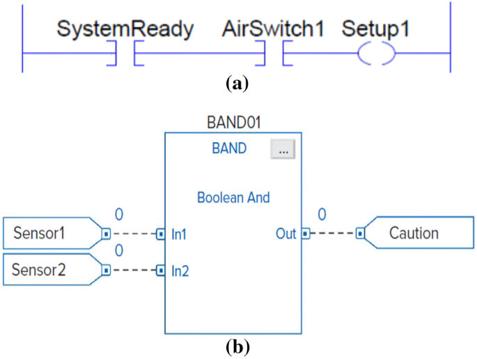
Ladder logic diagram (a) compared to FBD (b)
-
Function Block Diagram (FBD): interconnected graphical blocks represent process flow and parameters; see Fig. 4b.
-
Sequential Function Chart (SFC): a graphical language consists of states or steps (with associated actions) and transitions (with associated conditions) used to move from a current state to the next one. LD, FBD, and ST programs can be written into the SFC structure.
-
Structured Text (ST): a high-level language that resembles “C” or “Pascal”.
-
Instruction List (IL): a low-level language uses mnemonic instructions; it resembles assembly.
-

2.2 HMIs and other terminals
-
HMIs: are user interface panels or dashboards that connect operators to field devices; to monitor or control. HMIs used to be simple, isolated, and dedicated panels consist of electrical pushbuttons, lights, switches, etc. HMIs, for instance, enable operators to put the PLC-BS in “Auto” or in “Manual”, open or close valves, acknowledge alarms, stop certain devices, etc. Nowadays, HMIs are more sophisticated and complex. They are built on widely known OS like Windows and run Windows based programs. They can be equipped with touch screens, ActiveX, database, and remote access capabilities; and some are even servers or web based. The need to monitor, visualize, archive, or even remotely access related data, have driven the HMIs to a different highly advanced stage. Nowadays, HMIs have evolved more into computer-based solutions; e.g. WinCC and FactoryTalk View. HMIs facilitate the access to any industrial process or event; avoiding operators going through ladder logic code. They can be used as stand-alone terminals, PCs based, or even as smart phone apps. HMIs support leading industrial network protocols such as Ethernet, PROFINET, Modbus, ControlNet, etc. They can be utilized to control large systems and most of PLC-BS related devices. In addition, many computer-based HMIs are equipped with all required PLC software and tools; like TIA and RSLogix. Such HMIs enable users to access, monitor, modify, or even program any associated PLC codes; online of offline.
-
DTUs (Display Terminal Units) allow the operators to control and monitor associated production processes, events, or alarms. They display the status of gathered information graphically. They are similar to HMIs but less sophisticated. They run on known OS; Like Windows CE. Windows CE, for instance, comes with ActiveX controls, remote connectivity via Ethernet, VNC, and FTP.
-
HTU (Historians Terminal Units) are logging devices which are based on servers or PC units. They are used to log or archive (events, alarms, activities etc.), monitor PLC related devices and activities. They are typical IT computers and by that suffer the same vulnerabilities.
2.3 Peripherals and I/O devices
The I/O devices are usually interconnected via communication industrial networks or physical point to point connection to monitor or control activities. They typically consist of:
-
Sensors: Provide the status of a device or process (like temperature, flow rate, position, etc.) as inputs to the PLC by converting physical information into electrical signals.
-
Actuators: Convert received transmitted electrical signal outputs into physical action. Examples of actuators: valves, solenoid, stepper motor, power relays, etc.
-
Other devices that have physical operations: industrial Robots (welding, material handlers, vision robots, sealing, etc.), elevators, etc.
2.4 Networks
Data communication among PLCs and field devices can be established via industrial communication networks. Those networks have to be reliable, real-time, and accurate to handle data monitoring and data controllability among various devices. Originally industrial networks started as point-to-point communication link, limited and straight forward. A good example of that is a serial communications link. A signal is used to be transmitted (carried from the PLC to other devices or actuators i.e. an output) or received (sent to the PLC from a sensor i.e. an input)—via point to point connection or terminal cards. Although it is limited, a point-to-point serial communications link is less vulnerable to security threats. However, with the advancement of technology and emerged needs, industrial networks evolved to more complex level. LAN (Local Area Network) and WAN (Wide Area Network) are good examples. Some industrial networks can handle diagnostics and power up interconnected related devices in addition to carrying signals from/to PLC via I/O modules or scanners like DeviceNet. Field devices, for instance, like I/O devices or modules have become more networked and software (firmware) based. I/O module devices are now connected, locally, or remotely, to industrial networks to get better modularity, reduced cost, less wiring—see Figs. 5 and 6, easy and quick installation or maintenance, and good diagnostics [15, 16]. But that advancement of industrial communication networks come with more vulnerability to cyber attacks or threats; discussed later on.

DeviceNet bus with scanner and ArmorBlocks [16]

DeviceNet architucture [16]
Some of the current and widely used industrial networks are:
-
Modbus.
-
PROFINET.
-
PROFIBUS.
-
DeviceNET.
-
ControlNet.
-
EtherNet/IP.
Generally, industrial networks consist of I/O devices, Scanners modules, and network cables. A PLC communicates to other sensors, actuators, or devices via one of the above networks. DeviceNet, which is widely used would be a good example of such advancements. DeviceNet consists mainly of the following modules: DNET Scanner, ArmorBlock/ArmorPoint, and Flex I/O [16], as shown in Figs. 5 and 6. Each module has its own firmware that could be vulnerable to security threats (Fig. 7).

DeviceNet bus with scanner reduces wiring [16]
3 PLC-BS threats and vulnerabilities
The following is a categorization of the threats against PLC-BS:
-
PLCs code vulnerabilities.
-
PLCs vulnerabilities.
-
HMIs and DTUs vulnerabilities.
-
Field devices vulnerabilities.
-
Network vulnerabilities.
-
Netwrok segmentation vulnerabilities.
3.1 PLC code vulnerabilities
Attention to PLC code vulnerabilities has not been a great concern as that of network related ones. That is because companies, developers, and programmers assume that the codes that are running within the PLCs safe and secure as long as no network intruder. But that is not the case. PLCs codes can carry within their own destructive threats and vulnerabilities that can be exploited by hackers or regular disgruntled users. The vulnerabilities come from the way the code is written or designed. The following are some typical examples:
-
Incomplete faults or alarms handling: a malicious code can disable or silent certain alarms. Basically, the manipulated logic code does not handle or scan all critical faults, alarms, related logic code, or parameters. By that operators would not notice the problem since a malicious code is going stealthy and unnoticed way; i.e. recognizing threats after the damage occurs [17].
-
Fake outcomes: occurs when PLC code skips certain rungs or parameters; e.g. improper usage of MCRs (Master Control Reset) which normally used to disregard non-retentive instructions once enabled.
-
Snooping code: a user can utilize certain instructions, such as “ADD ON” instruction, that can be exploited to log or monitor some sensitive data or parameters. Those instructions can be added to any logic code and go unnoticed.
-
Overflow: occurs when an instruction or an operand parameter length of input or output do not match what the PLC is expecting. That usually occurs because of unskilled programmers or when a malicious attack manipulates parameters.
-
Duplicated instructions: For some instructions, as the one shown in Fig. 8, if they are duplicated in more than one rung, their values will be unpredictable, affecting the logic code and the process controlled by it. Also, that will make it harder to debug the code and find or identify the problem [17].
Fig. 8 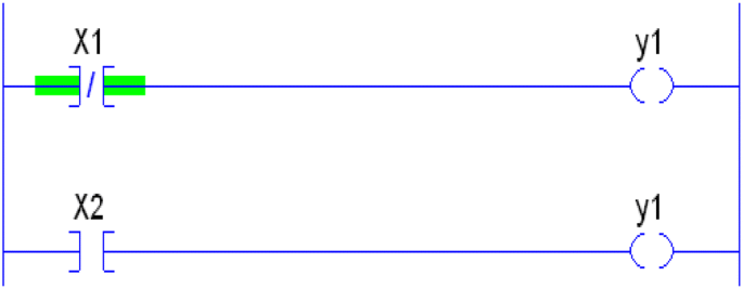
Duplicating OTE operand [17]
-
Unused tags: defining tags in the controller database that are not used in the logic could increase the level of threats; especially if the tags are not driven by a well-defined ladder logic.
-
Missing certain coils or instructions: can result in an undesired behavior. A user can exploit such situation to add an improper output that could severely affect the logic code and the associated controlled hardware. For instance, if outputs—defined as Y1, Y11, and Y2 in the controller database—are used in the code, see Fig. 9, but the value of Y2 never been driven by the logic, a user can exploit this defined instruction for malicious attacks within the logic code. Fig. 9 shows a way to correct such scenario; making sure the value of Y2 is driven by clear well-defined logic [17] (Fig. 10).
Fig. 9 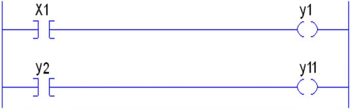
The logic is missing related inputs that feed Y2 [17]
Fig. 10 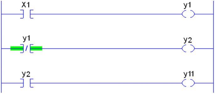
Outputs instructions are properly energized [17]
-
Bypassed instructions: when an instruction is bypassed by an empty parallel branch, see Fig. 11, it affects the rung condition-out. When hackers or regular developer use such techniques, it would go unnoticed which makes it difficult to debug and detect unless there is a clear compiler warning which often are disregarded. In addition, by passing could be done by misplaced jumpers (JMP) or jump to subroutines (JSR).
Fig. 11 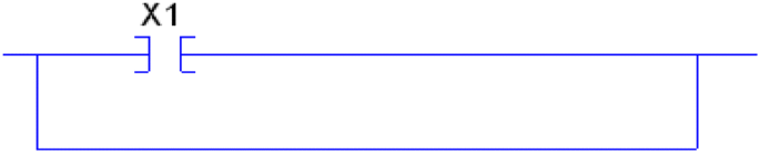
Using an empty branch as a short circuit [17]
-
Hard coded values: in certain situations, using hard coded parameters in instructions like comparative ones—see Fig. 12—could increase vulnerabilities. Parameters used in the comparison instruction can be manipulated by users, hackers, or malicious code without being noticed or constantly overwritten by the proper legitimate value. Fig. 13 shows a solution to protect “SourceB” value by constantly moving the real-time value of the counter into it [17] (Fig. 14).
Fig. 12 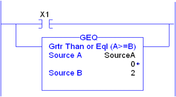
Numeric values are vulnerable [17]
Fig. 13 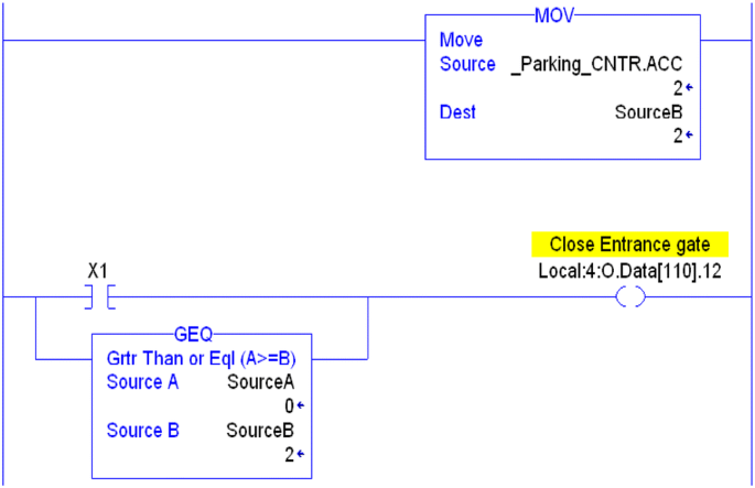
Compare real-time numeric values not card coded ones [17]
Fig. 14 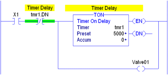
Racing condition [17]
-
Racing: misplaced branches, calls, or instructions can lead to inconsistent results. The logic is going to behave in an undesired way based on the unpredicted result of the race. In Fig. 15, “tmr1.DN”, which is a status of the timer “tmr1”, is placed just before the parallel branches creating a racing scenario between the timer or energizing “Valve01”. To avoid that, the instructions or the branches should be properly placed. “tmr1.DN”, see Fig. 16, shows the proper location of the instruction to prevent any racing [17].
Fig. 15 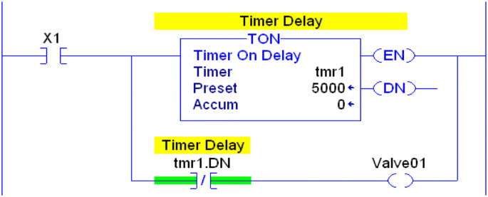
Racing condition solved [17]
Fig. 16 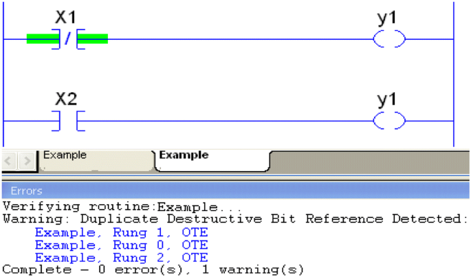
Compiler warnings [17]
-
Compiler warnings: PLC programmers pay great attention to the compiler errors but often overlook warnings. Compiler warnings could have a great value that could shed the light on improper codes or instructions that could be exploited by malicious attacks, see Fig. 16.
-
DoS: a compromised PLC can be done using malicious codes within the PLC logic code itself or because of improper coding. The following are some scenarios:
-
Infinite loops: using JSR (Jump to Subroutines) instructions, JMP instructions, nested timers, etc.
-
Fatal Faults: trigger certain faults that could cause PLC program to crash.
-


3.2 PLC vulnerabilities
Since PLCs run commercial operating systems, they are vulnerable like any other known OS; Linux or Windows. PLCs are not designed to be cyber-resilient since they have limited resources and are insecure by design. They were never designed for resilience against threats and attacks. The following are some examples of PLCs’ vulnerabilities:
-
PLC OS Vulnerability: PLC OS, such as VxWorks and OS-9, runs with the highest privileges and there is little memory protection between its tasks [18]. If the OS level vulnerabilities are exploited by an attacker, the system could be completely taken over allowing installation of malicious programs [19]. In general, PLCs’ OS are fragile when it comes to security: not frequent update or patches and not built anti-malware application. They are not frequently patched or updated because their networks are isolated or limited and un-upgradable firmware. More reports are issued regarding PLC OS vulnerabilities as in [20,21,22]. Another issue is that threats are not properly addressed and not widely reported. That is due to isolated networks, undocumented problems, or untraceable threats. It is hard, for instance, to update a firmware vulnerability or report it to vendors if PLCs are not directly connected to the vendors’ network or the internet. Vendors are not going to trace the problems occurred and get enough details. That makes patching and even revalidating feedback difficult; especially when PLCs’ have varieties of platforms.
-
Unrestricted uploads: having an access point to a PLC allows user to upload any malicious code to the PLC, manipulate the current running one, or even upload new firmware. PLCs typically do not check whether the uploaded code is from a verified trusted source or not. Also, PLCs have no capabilities to know whether the uploaded code is a malicious one or not; as long as it is compiled with no errors it can be uploaded and overwrites the current running one.
-
Unlocked Mode: PLCs are, most of the time, unlocked and not protected by any password. That would allow others to access the running logic code, monitor tags, manipulate the code, or even download a totally wrong or irrelated logic. Some vendors offer physical security key to lock the PLC, like turning the key to “Run”. A locked PLC prevents any code modification, update, or download.
-
PLCs codes can be exploited by malware to launch attacks to other PLCs that are on the same network.
3.3 HMIs and DTUs vulnerabilities
HMIs, DTUs, and HTUs are becoming more remotely accessible and interconnected with other networks and devices. As such, they are becoming more vulnerable and are attracting more hackers and threats. Like any other computers, they are vulnerable to any threats within the network and inherit all the vulnerabilities of the OS that are built on. For instance, HMIs have become generic or off-shelf software products that are built on or share common architecture computers or IT (Information Technology) systems like Windows OS, ActiveX, Java, etc. However, being generic software based, HMIs are becoming more vulnerable devices; as the attackers consider them regular PCs or yet another vulnerable operating system on the accessible infected network.
Attacking any HMI, including its related database, could lead to sever consequences on software (deleting or manipulating codes, alarms, or database records) as well as on hardware; especially that PLC-BS are immediate real-time systems. Attacks on software typically take advantages of unsecured networks or infected devices to create software manipulation or to steal confidential information. Software vulnerabilities can be exploited by real sophisticated cyber security attacks which consequently affect PLC-BS devices—HMIs, encoders, VFDs, motors, etc. Software attacks are summarized as follows:
-
External malware: that can be deployed either via internet, company’s network, or locally by users—e.g. inserting an infected USB into a HMI, Server, or PC that is on the PLC-BS network. Malwares can spy and damage industrial systems, delay or block networks, or even include PLC rootkits [23, 24].
-
Deception attacks: that includes a wrong unauthorized identity of a command sending device that can enable remote access and cause fatal damage to the software and hardware as well [25].
-
SQL Injection: affects Web based HMIs and servers with database applications (some HMIs or servers). It is a way to take control of a system or to insert an unexpected SQL statements into a query in order to manipulate a database [25].
3.4 Field devices vulnerabilities
One of the main vulnerabilities that can be exploited to manipulate and threat PLC-BS integrity and reliability is that coming out of improper or fake hardware status—inputs—or command—outputs. The threat occurs when the physical values of a hardware device is manipulated by sending or receiving fake values or signals. Tampering any value, even a bit, of an input or an output would deceive the PLC and lead to undesired ladder logic program results; endangering equipment, productivity, environment, and human life. That is accomplished by compromising the associated network which goes unnoticeably and without modifying any PLC logic code or firmware. In addition to faking their inputs/outputs, hardware devices can be vulnerable if the related PLC-BS programs are compromised; whether its HMI related or PLC ones—e.g. ladder logic code or database. The following is a summary of hardware vulnerabilities:
-
Fake inputs: status, parameters, or values of the compromised sensors or input devices (e.g. photo-eyes, part present sensors, safety emergency stops, VFDs—Variable Frequency Drives, regular and safety switches, etc.). Also, such vulnerabilities can lead to fake inputs carried out from the HMI to the PLC; e.g. operator’s manual selection, operator’s entered data, etc [23].
-
Fake outputs: status, parameters, or values of the compromised actuators or field devices (e.g. valves, VFDs, encoders, stepper motors, etc.) PLCs’ or HMIs’ outputs can also be faked; affecting other related devices [1, 23].
-
Manipulated inputs and outputs values by tampering data integrity of the PLC, HMI, or other devices such as manipulating their database or tags to create severe hardware damages or threats to PLC-BS [26].
-
Manipulated PLC ladder logic codes or HMI programs that damages hardware devices; Stuxnet exploited Siemens software to manipulate parameters of devices resulted in damaging critical hardware devices [1].
-
Manipulated HMI functionality or PLC ladder logic codes by slowing them down to severely affect production or lock it out.
-
Deactivated alarms and critical messages or warnings; delaying response time and make it slower to detect the problem.
3.5 Network vulnerabilities
Nowadays, most PLC-BS networks architecture distributes their functionalities across common or open standards protocols such as Wide Area Network (WAN) and LAN; Ethernet/IP, DeviceNet, ControlNet, Profibus, PROFINET, and Modbus. However, that advancements have increased vulnerability and threats; they lack security-integrated mechanisms and they become less obscure to hackers [24]. Not providing security mechanisms to protocols makes the network vulnerable to:
-
Packet manipulation (latency, spoofing, eavesdropping, deletion, etc.) [25].
-
Attacks on the communication stack: network layer, transport layer, application layer and the implementation of protocols (TCP/IP, OPC, ICCP, etc.) [18].
-
Remote or local field devices attacks; Intelligent Electronic Devices (IEDs).
-
Backdoors and Holes in Network Perimeters [3].
-
Database attacks.
-
Communications jamming, blocking, or hijacking; MITM (man-in-the-middle attack) [29].
3.6 Network segmentation vulnerabilities
Many companies still assume that they are safe and secure if their industrial networks are off the internet or isolated [30]. There are still some who believe that segmenting a network as in Fig. 3 keeps PLCs networks secure and safe. They assume that air gapped industrial network, which is a way of network segmentation, secures all PLCs and associated field devices including HMIs. But segmenting the Industrial Control Systems (ICS) network this way is not secure enough for the following reasons:
-
USB threat: the malicious attack could be deployed by infected USB.
-
Inherited: a malicious attack can be carried on by another infected computer or HMI that it is plugged to the same PLC-BS network. Also, some worms can go from one PLC to another PLC if they are on the same networks.
-
Disgruntled employees: an upset employee can create major damage and harms. He or she can sabotage the code, infect HMIs or PCs, write dormant malicious code within the ladder logic, or even open certain ports to hackers.
-
Bad code practice: a programmer might inadvertently write pieces of code that might damage certain machine or create DoS; e.g. infinite loops.
-
Stealthy access: some vulnerabilities might take years before noticing them. There job is not to create direct damage. They are there just to eavesdrop, collect, and steal sensitive information and data.
4 Lack of data forensics
Whenever an attack occurs, a forensic investigation must take place in order to figure out the causes and responsibilities. It is typical to collect related data. By analyzing and reverse engineering all needed collected data, we can get better understanding of the attack’s behavior, elements, techniques, etc. Also, further similar malicious attacks can be prevented and stopped. Since PLC-BS are critical and widely used in automated industries and critical infrastructure facilities, a thorough forensic investigation would have been a great help because of the following:
-
To identify the root cause of the attack.
-
To identify the potential elements and devices involved or exploited.
-
To identify possible risks and weaknesses.
-
To identify devices status and configuration just before the attack.
-
To find the proper remedy of the attack and prevent future similar reoccurring ones.
Unfortunately, forensic methods or tools are difficult to apply or use in PLC-BS. Unlike traditional IT systems and related devices, PLC-BS are more complex and custom-made. The difficulties or impediments that make applying digital forensic very challenging—if not impossible most of the time—are as follows:
-
Continuity: PLC-BS are continuously fed by field devices and I/O’s. Mainly they are real-time devices that continuously being updated with newer information; tracing previous ones would be hard if there are no continuous incremental backups.
-
Volatility: critical information of running programs and hardware that can be used as an evidence is located within volatile memory. PLCs, for instance, do not have proper hardware and software that log thorough code or firmware modifications or updates.
-
Fast Response: since PLC-BS are real-time devices that are continuously fed by updated newer information, delaying forensic response would make it more difficult to analyze and trace the problem. The slower the response is, the less related data will be resided within the volatile memory; overwritten by newer ones.
-
Validity and availability: Being real-time systems, PLC-BS care much about the validity, integrity, and availability of data more than security, encryptions, or backups. Slowing the scanning time of any running systems would create unfavorable problems. Therefore, using any tools or methods that could slow down PLC-BS would not be tolerated. That makes it difficult to embed any typical forensic tool.
5 PLC-BS security recommendations
The following are some recommendations to keep PLC-BS protected against threats or at least mitigate the risks:
-
Security First: as industries consider safety as a main factor while designing, updating, or functioning any PLC-BS, security should be paramount. That must consider the hardware, software, and networks. Companies have to come up with more detailed risk assessment, responses, and standardizations before implementing any PLC-BS projects.
-
Cybersecurity is everyone’s responsibility. All employees should be always aware and concerned about security. Employees should immediately report any insecure practice, insecure device, or skeptical behave.
-
Cybersecurity must be an organization culture. For instance, an organization should offer periodic security training to its employees. Employees should be aware of the security threats and wrong practices that might affect their work areas and systems.
-
Roles and Authentication: privileges to access information and devices should be properly restricted and well considered before assigning them to the employees. Privileges should be well validated, controlled, logged, and monitored (use unique IDs or access credentials). Unauthorized or non-monitored activity should be prevented or at least reduced to the minimum. Users should only have access to their daily related work and tasks. Automatic logging review and monitoring of users might also help.
-
Air-gapped network: PLC-BS systems should have their own isolated private networks, as much as possible, or at least clearly distinguished from other networks.
-
Redundant files backup and recovery tools: use several ways and tools including scripts to backup critical files and make it handy to recovery it or use it when needed.
-
Daily checkup and comparison: as companies are so concerned about safety before and during running production lines, they should worry more about the integrity of the files they are running on the PLCs or the HMIs. That should be done by having a software tool that compares the ladder logic against the original trusted master file before starting the new production lines. There is always a chance that someone might sabotage the logic or create a dormant malware within the ladder logic code the goes unnoticed.
-
Remote access and IoT (internet of things): must be restricted either to certain device, areas, or sometimes disabled. If needed, it must only be enabled for limited duration and used by internal trained personnel from an approved monitored and controlled device; all communications should be filtered and checked. Systems or devices that do not need to be connected to other networks, including internet, must be properly segregated and isolated to avoid any threat [31].
-
USB ports should be physically disabled on HMIs and on any other associated PCs. Only authenticated and approved USBs are to be allowed and must be used by administrators. Malware, like Stuxnet—spread via SCADA network through an infected USB storage device.
-
Spare port of any device should be disabled.
-
System logging: must be generated and kept for a reasonable amount of time in case are needed if any thing goes wrong.
-
Periodic system auditing and periodic penetration testing.
-
Continuous vulnerability and threats assessment and pre-emptive solutions.
-
Periodic risk assessment and analysis. Risk assessment answers questions like: what can go wrong? what is the probability that it would go wrong? and what is the impact or what are the consequences [32, 33]?
-
A cost–benefit analysis (CBA) is important, but without compromising security, safety, and data real-time validity, integrity, and availability.
-
Dedicated and protected devices: limit connection to PLC-BS to certain dedicated devices. Make sure any end-user device or PC is safe and protected (e.g. antivirus and other security apps).
-
Periodic updates: keep software including firmware up-to-date to reduce vulnerability and threats by deploying approved patches or updates from dedicated approved and safe PCs.
-
Intrusion system detection: that should also include ‘traditional’ perimeter protection (e.g. antivirus, firewalls, etc.). They should always be kept up-to-date and ON.
-
PLC-BS as an overall should be resilient and secure. Do not just focus on securing certain insecure field devices. Securing the whole systems is critical and a must.
-
It is impossible to have 100% risk free system. But we should make it harder on any attacker to initialize any major or massive attack. If stopping a malicious attack is difficult, at least slow it down. Stopping or slowing down any attack can be done through fast detection, network segmentation, and recovery steps.
6 Next generation: secure by design
Currently, several attempts or researches have been done to enhance security or add some security features to PLC and PLC based devices. That is summarized as follows:
-
PLC signed firmware and secure boot.
-
High percentage of ICS protocols will be able to integrate authentication into certain protocols. ICS Protocols authentication will prevent attackers from spoofing or sending illegitimate commands.
-
IPsec communications protocol between Windows based computers and a few PLCs—Modicon M580—is now somehow supported. IPsec is implemented only among certain modules for authentication header protocol and uses pre-shared keys rather than certificates [34].
-
Security Logging: get ICS security logs into a SIEM; partially implemented in Modicon M580 [34].
-
Disabling unused Ethernet ports.
-
Access Control List (ACL): restricts access by IP address based on the administrator criteria, used by Modicon M580 safety PLC [34].
-
Syslog: a few PLCs, Modicon M580 safety PLC, have started supporting syslog. Security events or some PLC logs can be exported and managed [34].
-
For old PLC-BS, add certain modules in front of the existing controllers to add or enhance security functions.
Those critical improvements are yet not widely adaptable or applicable. Mainly, most of PLC-BS can’t adapt or integrate those features due to limited features and resources, backward compatibility problems, limited compatible modules, PLCs’ scan time delay, and high costs which might require a major rip and replace. Some of the drawbacks of the above enhancements:
-
Adding IPSec to M580 PLC consumes extra 10ms for reading 10,000 variables [34].
-
IPsec is exclusively used between M580 PLCs and Windows computers. It is not built to support communications among M580 PLCs [34].
-
Certain encryptions and some added security values may not work with some field devices—like sensors or armorblocks. Several field devices have limited resources. Even it was to be feasible to encrypt some devices, updating the algorithm of those field devices would be a difficult task. Also, if a few devices haven’t been updated or they are non-updatable, vulnerabilities are increased risking the whole PLC-BS.
Nevertheless, PLCs are still far from being capable to be self-aware PLCs; know what is running inside. They are not capable to detect any malicious codes running within, warn of suspicious behavior, or intelligently eliminate any eminent or suspicious threat;
7 Conclusion
In this paper, we have provided an overview of PLCs—languages and hardware—in addition to an overview of associated industrial networks, field devices, HMIs, and DTUs. We have summarized the major vulnerabilities of PLC based devices and listed each group under its proper categorization. The vulnerabilities and threats against PLC_BS are categorized as: PLCs code vulnerabilities, PLCs vulnerabilities, HMIs and DTUs vulnerabilities, field devices vulnerabilities, network vulnerabilities, and network segmentation vulnerabilities. Every category shows its associated vulnerabilities and threats that could be exploited by attackers or malwares. A special attention has been given to illustrate, analyse, and evaluate certain ladder logic codes and bad programing practices. Not writing a PLC code professionally and up to recommendations provided would increase unnoticed vulnerabilities and threats. The absence of forensic data is yet another challenging weakness that we have discussed. Not having adequate and detailed forensics would encourage hackers to exploit such missing feature to cover their traces and further similar risks or attacks. It would be hard if not impossible to reverse engineering any attack and collect enough evidences among PLCs. In addition, we have provided recommendations and suggestions to avoid future vulnerabilities and threats. Following those recommendations, would highly mitigate, reduce, or eliminate malicious attacks or threats. Finally, we have provided an overview of the ongoing work of upcoming “secure by design” PLCs. Upcoming next generation PLCs and related security solutions have been presented; showing some features and challenges. We have explained the advantages of next gen PLCs—like Modicon M580 safety PLC—and their limitations; especially when it comes to resources, costs, and backward compatibility.
Abbreviations
- OT:
-
Operational technology
- PLCs OS:
-
Programmable logic controllers operating systems
- SCADA:
-
Supervisory control and data acquisition
- HMI:
-
Human–machine interface
References
Falliere N, Murchu LO, Chien E (2011) W32.stuxnet dossier. Symantec. Technical report http://www.symantec.com/content/en/us/enterprise/media/security_response/whitepapers/w32_stuxnet_dossier.pdf. Accessed 25 July 2019
Langner R (2011) Stuxnet: dissecting a cyberwarfare weapon. IEEE Secur Privacy 9(3):49–51
Nash T (2005) Backdoors and holes in network perimeters—a case study for improving your control system security, vol 1.1, August 2005, Vulnerability and risk assessment program, Lawrence Livermore National Laboratory, UCRL-MI-215398
Gostev A (2012) The flame: questions and answers. Securelist Blog, Kaspersky. https://www.securelist.com/en/blog/208193522/The_Flame_Questions_and_Answers. Accessed 25 July 2019
Lee RM, Assante MJ, Conway T (2016) Analysis of the cyber attack on the ukrainian power grid. Technical report, E-ISAC
Muncaster P (2011) Stuxnet-like attacks beckon as 50 new Scada threats discovered 21st Apr. 2011. http://www.v3.co.uk/v3-uk/news/2045556/stuxnet-attacks-beckon-scada-threatsdiscovered. Accessed 25 July 2019
Overload: Critical Lessons from 15 Years of ICS Vulnerabilities. https://www2.fireeye.com/rs/848-DID-242/images/ics-vulnerability-trend-report-final.pdf. Accessed 25 July 2019
https://media.kasperskycontenthub.com/wp-content/uploads/sites/43/2016/07/07190426/KL_REPORT_ICS_Statistic_vulnerabilities.pdf. Accessed 25 July 2019
Cheminod M, Durante L, Valenzano A (2013) Review of Security Issues in Industrial Networks. IEEE Trans Ind Inform 9(1):277–293
https://www.isa.org/standards-publications/isa-publications/intech-magazine/2012/october/system-integration-iec-61131-3-industrial-control-programming-standard-advancements/. Accessed 25 July 2019
PLC security risk: controller operating systems—Tofino industrial security solution. www.tofinosecurity.com
Zhang Z, Susilo W, Raad R (2008) Mobile ad-hoc network key management with certificateless cryptography. In: 2nd international conference on signal processing and communication systems, ICSPCS 2008. IEEE
Qazi S, Raad R, Mu Y, Susilo W (2013) Securing DSR against wormhole attacks in multirate ad hoc networks. J Netw Comput Appl 36(2):582–592
Qazi S, Raad R, Mu Y, Susilo W (2018) Multirate DelPHI to secure multirate ad hoc networks against wormhole attacks. J Inf Secur Appl 39:31–40
Eccles LH (1998) A smart sensor bus for data acquisition. Sensors 15(3):28–36
Serhane A, Sharif M, Chehadi H, Harb A, Moshen A (2017) Optimizing solar systems using DeviceNET. In: 2017 29th international conference on microelectronics (ICM). IEEE
Serhane A, Raad M, Raad R, Susilo W (2018) PLC code-level vulnerabilities. In: 2018 international conference on computer and applications (ICCA), Beirut, pp 348–352
Zhu B, Joseph A, Sastry S (2011) A taxonomy of cyber attacks on scada systems. In: 2011 international conference on internet of things and 4th international conference on cyber physical and social computing, pp 380–388
Zhang Z, Lv Z, Mo J, Niu S (2014) Vulnerabilities analysis and solution of VxWorks. In: ICTCS, 2nd international conference on teaching and computational science, pp 94–97.
US-CERT vulnerability note #362332: Wind River Systems VxWorks debug service enabled by default, 23 July 2012
US-CERT vulnerability note #840249: Wind River Systems VxWorks weak default hashing algorithm in standard authentication API (log in Lib), 10 May 2012
ICS-ALERT-12-020-03—Schneider Electric Modicon Quantum Multiple Vulnerabilities, January 20, 2012
Govil N, Agrawal A, Tippenhauer NO (2018) On ladder logic bombs in industrial control systems. In: Katsikas S et al (eds) Computer Security. SECPRE 2017, CyberICPS 2017. Lecture Notes in Computer Science, vol 10683. Springer, Cham. https://link.springer.com/chapter/10.1007/978-3-319-72817-9_8. Accessed 25 July 2019
https://media.kaspersky.com/en/business-security/enterprise/KICS-Solution-Overview-EN.pdf. Accessed 25 July 2019
Amin S, Litrico X, Sastry S, Bayen AM (2013) Cyber security of water scada systems Part I: analysis and experimentation of stealthy deception attacks. IEEE Trans Control Syst Technol 21(5):1963–1970
Sridhar S, Manimaran G (2010) Data integrity attacks and their impacts on Scada control system. In: IEEE PES general meeting, pp 1–6
Ten CW, Hong J, Liu CC (2011) Anomaly detection for cybersecurity of the substations. IEEE Trans Smart Grid, PP, p 1
Premaratne UK, Samarabandu J, Sidhu TS, Beresh R, Jian-Cheng T (2010) An intrusion detection system for IEC61850 automated substations. IEEE Trans Power Deliv 25:2376–2383
Mallouhi M, Al-Nashif Y, Cox D, Chadaga T, Hariri S (2011) A testbed for analyzing security of SCADA control systems (TASSCS). In: Proceedings of the IEEE/PES innovative smart grid technologies (ISGT), pp 1–7
Gazijahani FS, Salehi J (2017) Robust design of microgrids with reconfigurable topology under severe uncertainty. IEEE Trans Sustain Energy 9:559–569. https://doi.org/10.1109/TSTE.2017.2748882
Minoli D, Sohraby K, Occhiogrosso B (2017) IoT considerations, requirements, and architectures for smart buildings—energy optimization and next generation building management systems. IEEE Internet Things J. 4:269–283. https://doi.org/10.1109/JIOT.2017.2647881
Cherdantseva Y, Burnap P, Blyth A et al (2016) A review of cyber security risk assessment methods for SCADA systems. Comput Secur 56:1–27
Gazijahani FS, Salehi J (2017) Optimal bi-level model for stochastic risk-based planning of microgrids under uncertainty. IEEE Trans Ind Inform 14:3054–3064. https://doi.org/10.1109/TII.2017.2769656
https://download.schneider-electric.com/files?p_enDocType=Brochure&p_File_Name=998-20233655_GMA.pdf&p_Doc_Ref=998-20233655_GMA. Accessed 20 May 2019
Author information
Authors and Affiliations
Corresponding author
Ethics declarations
Conflict of interest
On behalf of all authors, the corresponding author states that there is no conflict of interest.
Additional information
Publisher's Note
Springer Nature remains neutral with regard to jurisdictional claims in published maps and institutional affiliations.
Rights and permissions
About this article

Cite this article
Serhane, A., Raad, M., Raad, R. et al. Programmable logic controllers based systems (PLC-BS): vulnerabilities and threats. SN Appl. Sci. 1, 924 (2019). https://doi.org/10.1007/s42452-019-0860-2
Received:
Accepted:
Published:
DOI: https://doi.org/10.1007/s42452-019-0860-2